manuals.online logo
Brands
  1. Home
  2. •
  3. Brands
  4. •
  5. Air Monitor
  6. •
  7. Transmitter
  8. •
  9. Air Monitor VELTRON III User manual

Air Monitor VELTRON III User manual

Precision Airflow Measurement
An ON
I
CON Brand
DOC-0005932 Rev. B
STEP 1: UNPACKING
PACKING LIST
• VELTRON III Transmitter
• RTD Temperature Sensor (Up to 2 if selected upon ordering)
• Quick Start Guide
• Factory Setup Sheet
INSPECTION & HANDLING
Veltron III should be carefully inspected for damage prior to Installation. Report damage to your freight department or
contact the delivery carrier.
WARRANTY
Air Monitor Corporation (Herinafter referred to as “Seller”) warrants that at the time of shipment, products sold pursuant
to this contract will be free from defects in materials and workmanship, and will conform to the specications furnished or
approved in writing by the Seller. Please refer to Conditions of Sale on the Air Monitor website for more information.
STEP 2: MECHANICAL INSTALLATOIN
Find an easily accessible location where electrical connections can be made and display readings can be taken from the
oor level. The mounting surface must be structurally sound and capable of withstanding a minimum weight of 10lbs
(4.5kg). Use the following screws for mounting.
For NEMA 1 Enclosure: For NEMA 4X Enclosure:
(4) Machine screws - #8-32 x 1.5” (4) Machine screws - HHMS 0.25-20 x 1.5”
(4) Wood screws - #8 x 1.5” (4) Wood screws - FHLS 0.25 x 1.5”
(4) Concrete screws - 0.1875” x 1.5” (4) Concrete screws - HHCS 0.25 x 1.5”
Precision Airflow Measurement
An ON
I
CON Brand
11451 Belcher Road South • Largo, FL 33773 • USA • +1 (727) 447-6140
www.airmonitor.com/hvac/ • [email protected]
Install the pressure or ow sensor per manufacturer recommendations. Use the table below to determine the appropriate
sensor tubing diameter based on the distance from the enclosure to the airow sensors. Contact Air Monitor for assistance
if longer tubing lengths are required.
Nominal/Min Tubing Internal
Diameter (in)
Tube Length Total (ft) Sensor Max Distance from
Transmitter (ft)
⅛ (0.125) 30 15
³⁄₁₆ (0.1875) 200 100
¼ (0.25) 500 250
⅜ (0.375) 1000 500
3. FIELD CHARACTERIZATION
The VELTRON III is equipped with a eld characterization (K-factor) feature which allows for the introduction of
gain and/or bias factors into the transmitter’s ow calculations. This feature is intended to be used in two types of
applications:
I. To adjust for ow measurement error as a result of highly distorted airow induced by upstream or downstream
ow disturbances.
II. To adjust the transmitter’s output to bring it into close correlation with eld measured ow data.
The K-Factor gain and bias values can be entered directly or the VELTRON III can calculate these values based on
measured and reference values from a 1, 2, or 3 point airow traverse.
For best results, Air Monitor recommends at least 2 velocity points be used to characterize the installation, with one
velocity reading taken in the bottom 1/3 of the operating range. When making this measurement, it is essential that
the velocity measurement be within the operating range of the Veltron III and airow sensor. The Veltron III can
simultaneously display ow velocity in actual and standard conditions. Before airow traverse readings are taken,
temporarily recongure the display to show both velocity readings and make sure the airow velocity does not exceed
the airow sensor cuto before any airow traverse readings are taken.
Number of Points
The number of data points (1-3) to be used for eld characterization.
Manual Characterization
ENT - Accept ESC - Leave UP/DN - Change
Exponent
Gain
0.500
1837.0
Characterization Calculator
ENT - Accept ESC - Leave UP/DN - Change
3
0.0Point 1
Reference
0.0Point 2
0.0
0.0
0.0
0.0
Vel III Points
Point 3
Flow Data Points
Number of Points
If you select the manual option in the eld characterization menu, you will be
provided with data entry elds for manually entering exponent and gain values.
This data will be calculated and provided by the balancer or others.
3 Points - For point 1, enter a ow rate or velocity that is in the bottom third of
the operating range. For point 2, enter a ow value that is in the middle third of
the operating range. For point 3, enter a ow value that is in the upper third of
the operating range.
QUICK START GUIDE
VELTRON III - Pressure & Flow Transmitter
INSTALLATION PROCEDURE
Visit the VELTRON III product page for
more information.
Air Monitor recommends that signal tubing between the transmitter enclosure and all sensors be stainless steel or copper
of the appropriate size. Use tees or manifolds to combine multiple sensors into single high and low pressure lines running
to the transmitter’s channel ttings for each channel. UV resistant, exible, plastic tubing specically designed for outdoor
use, such as Tygon R-3400 or equivalent, may also be used. Use brass inserts with the plastic tubing as required to ensure
a leak free connection. The connection types can be either compression ttings which are recommend with metal tubing
or barb ttings which are recommended for plastic tubing.
727.447.6140 Page 2 www.airmonitor.com/hvac/
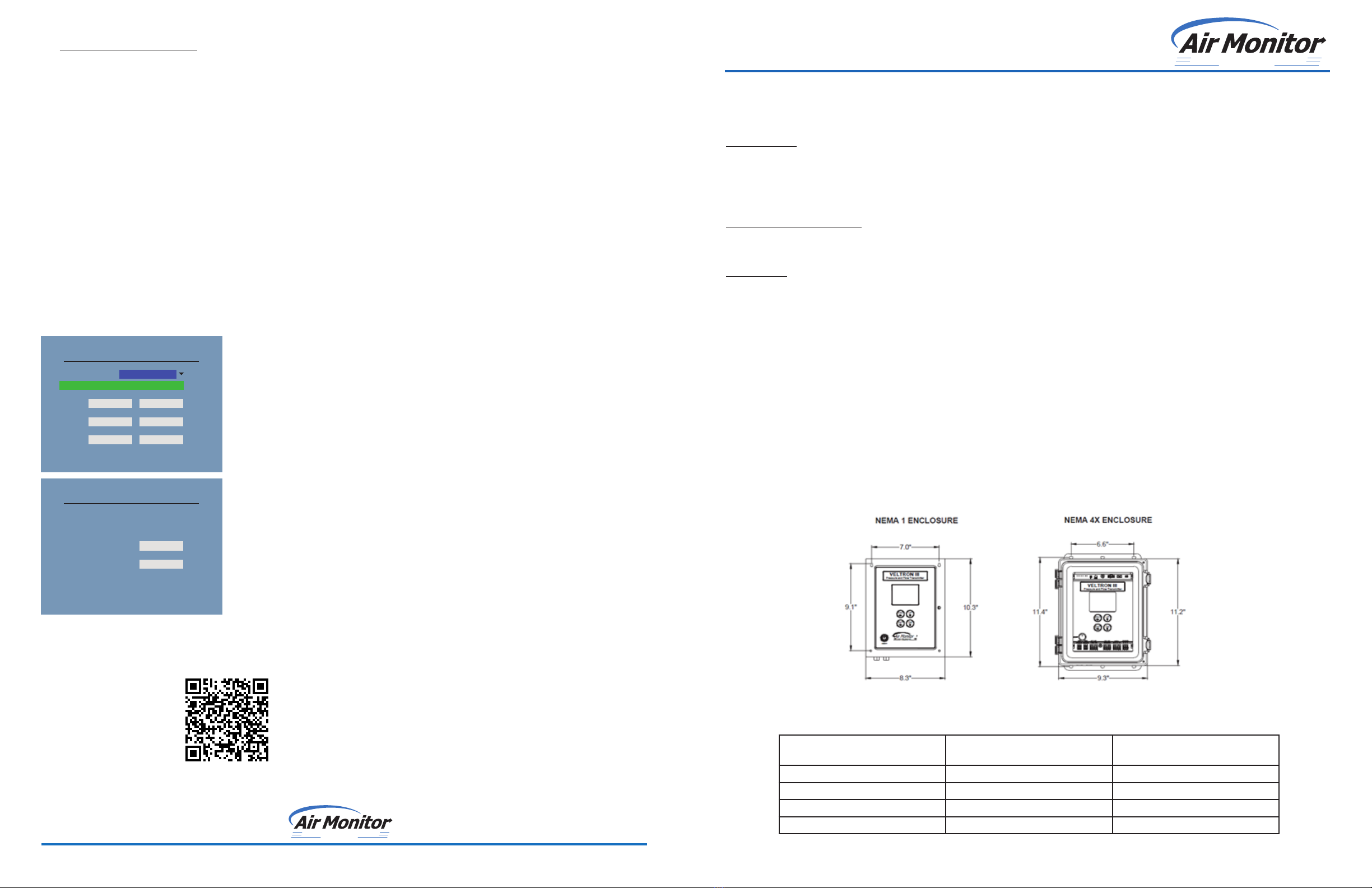
VELTRON III
QUICK START GUIDE
727.447.6140 Page 3 www.airmonitor.com/hvac/
VELTRON III
QUICK START GUIDE
STEP 3: ELECTRICAL INSTALLATION
1. POWER
I. Verify that correct AC/DC voltage is available at the power supply input terminals per its wiring diagram.
II. Input voltages should be supplied via one of the two methods below:
• 24 VAC, 15VA @ 24 VAC (40 VA with heater)
• 24 VDC, 10W @ 24 VDC (35W with heater)
2. CONNECTING VIA BACNET MS/TP
I. Power on unit to verify it is functioning properly. After verifying, power down the unit.
II. Wire RS485 cables to unit. The network cable connections are polarity sensitive and must be connected the
same way on every device (i.e. + to + and - to -). Shield drain connections should be daisy chained in the same
manner as the signal cables for RS485. The shield drain wire should be left unterminated at the end of the cable
and connected to earth only at the network master controller. Shield wires must not be connected to the RS485
connector on the Veltron III. The maximum number of devices allowed on an RS485 network segment without a
repeater is 32. Adding more than 32 devices to a single segment may reduce the transceiver output voltage to a
level that is too low to be distinguished from background noise on the cable.
III. Connect power to unit.
IV. Navigate to the Veltron III network conguration. Select Main MenugNetwork CongurationgBACnet or
MODBUS.
V. Congure device the Baud Rates, Device Address Range, Device Instance Range, and Max Master.
VI. Power cycle the device and it is now ready to connect to the controller or next device in the trunk.
3. ANALOG OUTPUT
I. For each analog output wire the two wires, the signal and the common for the device to provide 4-20mA, 0-5V, or
0-10V signal for each output.
II. Analog loop should not have power supplied to or it will damage the analog output.
4. RTD (IF SELECTED)
I. Remove the RTD from the transmitter enclosure (taped in bag at bottom).
II. Select a convenient mounting location(s) near the inlet or inside the air handler/duct to mount the RTD(s).
III. Use the supplied sheet metal screws to mount the RTD(s).
IV. Wire the RTD to the unit.
STEP 4: PROGRAMMING
TEMPERATURE FIELD CHARACTERIZATION
To navigate to the Temp Field Characterization menu. Select Main MenugTemp Field Characterization or System1/
System2gTemp Field Characterization for Dual Channel, Dual split.
I. If the device was congured for an RTD, the user will be prompted to enter a reference temperature to calibrate
the RTD in the eld.
II. If the device was congured without an RTD, the temperature will manually be entered into the Process
Temperature screen.
2. HUMIDITY CORRECTION
To navigate to the Humidity Correction menu. Select Main MenugHumidity Correction Option or System1/System2g
Humidity Correction Option for Dual Channel, Dual system.
This function allows the user to set the air to be adjusted for Supply Air, Return Air, or Custom. For supply air RH is set to
20% RH if Temp > 85°F and then switches to RH of 98% if <85°F. Return Air RH is set at 60% regardless of Temp rading
from RTD. For Custom you can enter your low RH value and high RH value, the Low RH value will be used when RTD Temp
is >65°F.
EARTH
GROUND
RS485(+) SHIELD
RS485(-) GROUND
+24 V AC/DC (L)
(-) COMMON (N)
+SIGNAL
-COMMON
Rb2 Ra
Rb1 (WHT)
3.
4. 2.
1.
H - High Pressure port connects to the high pressure side of a DP sensor
L - Low Pressure port connects to the low pressure side of a DP sensor
AMC Probes will be labeled TP=High Pressure, and SP=Low Pressure

Other Air Monitor Transmitter manuals

Air Monitor ELECTRA-flo G5 User manual

Air Monitor

Air Monitor ELECTRA-flo G5 User manual

Air Monitor AUTO-purge III User manual

Air Monitor

Air Monitor AUTO-purge III User manual

Air Monitor MASS-tron II/CEM User manual

Air Monitor

Air Monitor MASS-tron II/CEM User manual

Air Monitor VELTRON II User manual

Air Monitor

Air Monitor VELTRON II User manual

Air Monitor VOLU-flo/OAM II User manual

Air Monitor

Air Monitor VOLU-flo/OAM II User manual

Air Monitor VELTRON DPT 2500 User manual

Air Monitor

Air Monitor VELTRON DPT 2500 User manual

Air Monitor ELECTRA-flo G5 User manual

Air Monitor

Air Monitor ELECTRA-flo G5 User manual

Popular Transmitter manuals by other brands

GF 2260 instruction manual

GF

GF 2260 instruction manual

MODSTER Vector SR48 user manual

MODSTER

MODSTER Vector SR48 user manual

WIKA FLRU-SFI operating instructions

WIKA

WIKA FLRU-SFI operating instructions

SRK Electronics MFTX50 Operation and service manual

SRK Electronics

SRK Electronics MFTX50 Operation and service manual

Honeywell ADEMCO 5805-6 user guide

Honeywell

Honeywell ADEMCO 5805-6 user guide

VitBest EAWP-70-T user manual

VitBest

VitBest EAWP-70-T user manual

MG B5MS instruction manual

MG

MG B5MS instruction manual

Aidcall Touchsafe Pro Door Monitor V3.00a installation guide

Aidcall

Aidcall Touchsafe Pro Door Monitor V3.00a installation guide

YOKOGAWA vigilantplant DPharp EJX Series user manual

YOKOGAWA

YOKOGAWA vigilantplant DPharp EJX Series user manual

MuxLab Stereo Hi-Fi Balun Quick installation guide

MuxLab

MuxLab Stereo Hi-Fi Balun Quick installation guide

WisyCom MPR30-IEM manual

WisyCom

WisyCom MPR30-IEM manual

MGC UDACT-300A Installation and operation manual supplement

MGC

MGC UDACT-300A Installation and operation manual supplement

Ascon tecnologic H3 Line user guide

Ascon tecnologic

Ascon tecnologic H3 Line user guide

Questtel L-1SDI-FE-HD-TX user manual

Questtel

Questtel L-1SDI-FE-HD-TX user manual

SVP UDT-4K manual

SVP

SVP UDT-4K manual

DMP Electronics 1101-WINT installation guide

DMP Electronics

DMP Electronics 1101-WINT installation guide

Williams Sound T1-216 Specification sheet

Williams Sound

Williams Sound T1-216 Specification sheet

Masibus TT7S00-HR-S user manual

Masibus

Masibus TT7S00-HR-S user manual

manuals.online logo
manuals.online logoBrands
  • About & Mission
  • Contact us
  • Privacy Policy
  • Terms and Conditions

Copyright 2025 Manuals.Online. All Rights Reserved.