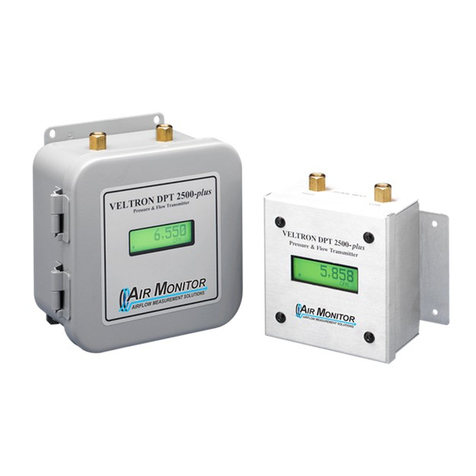
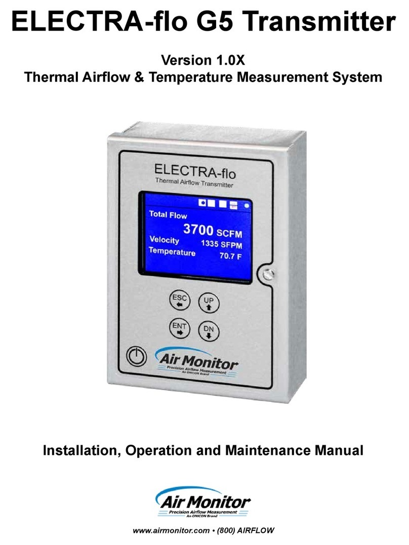
Air Monitor ELECTRA-flo G5 User manual

Precision Airflow Measurement
An ON
I
CON Brand
ELECTRA-o G5ELECTRA-o G5
Thermal Airow TransmitterThermal Airow Transmitter
Installation and Operation ManualInstallation and Operation Manual
DOC-0002681 Rev.D

ELECTRA-o G5 TRANSMITTER
Air Monitor Corporation 800.AIR.FLOW Page 2 airmonitor.com
SAFETY INFORMATION Regarding this Manual:
• This manual should be passed on to the end user.
• Before use, read this manual thoroughly to comprehend its contents.
• The contents of this manual may be changed without prior notice.
• All rights reserved. No part of this manual may be reproduced in any form
without Air Monitor’s written permission.
• Air Monitor makes no warranty of any kind with regard to this material,
including, but not limited to, implied warranties of merchantability and
suitability for a particular purpose.
•
of this manual. However, if any errors are found, please inform Air Monitor.
• Air Monitor assumes no responsibilities for this product except as stated in
the warranty. If the customer or any third party is harmed by the use of this
product, Air Monitor assumes no responsibility for any such harm owing to
any defects in the product which were not predictable, or for any indirect
damages.
SAFETY PRECAUTIONS:
The following general safety precautions must be observed during all phases of
installation, operation, service, and repair of this product. Failure to comply with
violates safety standards of design, manufacture, and intended use of the
product. Air Monitor Corporation assumes no liability for the customer’s failure to
in this manual, the protection provided by this product may be impaired.
The following messages are used in this manual:
WARNING
Messages identied as “Warning” contain information regarding the
personal safety of individuals involved in the installation, operation or
service of this product.
CAUTION
Messages identied as “Caution” contain information regarding potential
damage to the product or other ancillary products.
IMPORTANT NOTE
Messages identied as “Important Note” contain information critical to the
proper operation of the product.
ELECTRA-o G5 TRANSMITTER
Air Monitor Corporation 800.AIR.FLOW Page 3 airmonitor.com
TABLE OF CONTENTS
SECTION 1.0 GENERAL INFORMATION .................................................................................. 4
.......................................................................................................................4
........................4
...........................................................................5
.......................................................................................................6
...........................................................................7
....................................................................................................................7
.........................................................................................................................................7
SECTION 2.0 INSTALLATION..................................................................................................... 8
..........................................................................................................................................8
...............................................................................................................9
.......................................................................................................... 10
...................................................................................... 10
-.................................................... 11
- .................. 11
SECTION 3.0 OPERATION........................................................................................................ 12
-........................................................................................................................ 12
............................................................................ 13
.............................................................................................................................................. 15
............................................................................................................ 19
................................................................................................................ 29
......................................................................................................................................... 30
SECTION 4.0 MAINTENANCE, INSPECTIONS, TROUBLESHOOTING............................... 32
...................................................................................................... 32
............................................................................................................................. 32

ELECTRA-o G5 TRANSMITTER
Air Monitor Corporation 800.AIR.FLOW Page 4 airmonitor.com
SECTION 1.0
GENERAL
INFORMATION
1.1 PURPOSE OF THIS GUIDE
1.2 TYPICAL THERMAL
AIRFLOW MEASUREMENT
SYSTEM INSTALLATION
PROBE TO PROBE
CONNECTION
IN DAISY CHAIN
CONFIGURATION
SINGLE CABLE
CONNECTION
FROM PROBE
ARRAY TO
TRANSMITTER
EXTERNALLY MOUNTED
PROBES IN HORIZONTAL DUCT
ELECTRA-flo
Thermal Airflow Transmitter
LCD
DISPLAY
USER INTERFACE
KEYPAD
CONDUIT CONNECTION
FOR POWER INPUT
TRANSMITTER TO
PROBE ARRAY CABLE WITH
MINI-DIN SNAP AND LOCK
CONNECTOR
ON/OFF SWITCH
CONDUIT CONNECTION
FOR OUTPUT SIGNALS
Air Monitor
Precision Airflow Measurement
An ONICON Brand
This manual provides information regarding the installation, operation and
including its power connection and associated outputs. The complete system
inlet probes. Refer to supplemental documents for additional information.
interface for BACnet® or
Procedures guide, available at airmonitor.com.

ELECTRA-o G5 TRANSMITTER
Air Monitor Corporation 800.AIR.FLOW Page 5 airmonitor.com
*
1.3 STANDARD FEATURES AND SPECIFICATIONS*
ELECTRA-o G5 Transmitter
0 to 99% RH, non-condensing
•
•
•
•
Menu driven user interface via four (4) push buttons
•
two (2) ½" conduit openings
•
UL 60730
BTL
FCC

ELECTRA-o G5 TRANSMITTER
Air Monitor Corporation 800.AIR.FLOW Page 6 airmonitor.com
Electra-o G5 Transmitter
A= Feature Set
B= Enclosure
C= Outputs
0 = None
2 = Two (2) analog outputs and one (1) alarm output
D = Communications
0 = None
E = Input Power
F=Wiring Connection
SPC=Special Cong
000 = None
Model Number Coding = E-o G5-AB-CDEF (-SPC)
1.4 MODEL NUMBER CODIFICATION

ELECTRA-o G5 TRANSMITTER
Air Monitor Corporation 800.AIR.FLOW Page 7 airmonitor.com
equipment. Inspect equipment for any damage (if damaged, contact Air Monitor
•
•
• (1) Installation and Operation Manual
•
Review the factory setup-up information sheet provided and verify that the
Please contact the Air Monitor customer service department if you have
questions.
these transmitters to direct sunlight, temperature extremes or excessive vibration.
The operating ambient air temperature range for both enclosures is -20°F to
140°F.
vibration. Whenever possible, avoid exposure to direct sunlight. The operating
ambient air temperature range is -20°F to 140°F.
available when contacting Air Monitor for assistance regarding your product.
1.5 CHECKING THAT YOU
RECEIVED EVERYTHING
1.6 WORKING ENVIRONMENT
1.7 SERIAL NUMBER

ELECTRA-o G5 TRANSMITTER
Air Monitor Corporation 800.AIR.FLOW Page 8 airmonitor.com
Careful attention to the site selection for the system components will help the
installers with the initial installation, reduce start-up problems, and make future
selecting a site for mounting the system components, consider the criteria under
• The transmitter must be installed in a way that will allow the probe-to-
cable lengths are 10’ with optional 25’, 50’ and 100’ cables available.
•
For dual systems, all probes can be interconnected and brought back to the
transmitter with a single cable, or each individual system can have a home run
to the transmitter.
•
2.1 SITE SELECTION
systems. Air Monitor support personnel are available to assist with technical
The installer should use good trade practices and must adhere to all state and
local building codes.
application. If any problems or discrepancies are detected, contact Air Monitor’s
SECTION 2.0
INSTALLATION

ELECTRA-o G5 TRANSMITTER
Air Monitor Corporation 800.AIR.FLOW Page 9 airmonitor.com
1. Two (2) 0.188 mounting slots.
2.
3.
4.
5.
6.
2.2 TRANSMITTER DIMENSIONS
ELECTRA-flo G5
Thermal Airflow Transmitter
ESC UP
ENT DN
Air Monitor
Precision Airflow Measurement
AnONICON Brand
2.3"
4.9"
3.5"
6.9"
7.4"
7.8"
NEMA 1 ENCLOSURE
ESC
ENT DN
UP
ELECTRA-flo G5
Thermal Airflow Transmitter
Air Monitor
Precision Airflow Measurement
AnONICON Brand
10.5"
NEMA 4X- FIBERGLASS
ENCLOSURE
8.5"
6.4
NEMA 4X- STAINLESS STEEL
ENCLOSURE
4.3"
1
8.3"
10.3"
6.0"
10.8"
6.0"
10.9"
2
3
4
5
6
5
6

ELECTRA-o G5 TRANSMITTER
Air Monitor Corporation 800.AIR.FLOW Page 10 airmonitor.com
2.3 TRANSMITTER
INSTALLATION
2.4 TRANSMITTER WIRING
CONNECTIONS
Find an easily accessible location where electrical connections can be made and
must be structurally sound and capable of withstanding a minimum weight of
40lbs (18kg). Use the following screws for mounting.
IMPORTANT NOTE
This section may be skipped if the transmitter was ordered factory mounted
to the station.
secured using all four mounting holes.
Reasonable consideration should be given to clearances for electrical
connections.
Once a suitable location is found, use the transmitter as a template to mark the
centers of the four mounting holes.
ESC UP
J12
RESET
U7 U35
J10
TERM
BIAS
ALARM
AO1 / AO2 BACnet 24 V INPUT PWR
NO C NC
+ COM / + COM D+ D- G SH L N G
J1 J2 J3 J4
J5 J6SENSORS
S1
J12 3
TERM
BIAS
ALARM
AO1 / AO2 BACnet 24 V INPUT PWR
NO C NC
+ COM / + COM D+ D- G SH L N G
J1 J2 J3 J4
J5 J6SENSORS
S1
ON
TERM
BIAS
5
4
1
2
ELECTRA-flo G5
Thermal Airflow Transmitter
ESC UP
ENT DN
Air Monitor
Precision Airflow Measurement
An ONICON Brand
1.
2. User programming and display keys.
3.
4.
Refer to section 2.4.2 for additional information.
5.
information.

ELECTRA-o G5 TRANSMITTER
Air Monitor Corporation 800.AIR.FLOW Page 11 airmonitor.com
2.4.1 ELECTRA-o G5 Power/ Signal Connections
2.4.2 ELECTRA-o G5 Analog Outputs & Serial Communication
TERM
BIAS
ALARM
AO1 / AO2 BACnet 24 V INPUT PWR
NO C NC
+ COM / + COM D+ D- G SH L N G
J1 J2 J3 J4
J5 J6
SENSORS
S1
INPUT POWER AND ALARM CONNECTION
TB - J3
ALARM CONNECTION
TB - J4
INPUT POWER
GROUND (G)
(-) COMMON (N)
(+) 24 V AC/DC (L)
NORMALLY CLOSED CONTACT (NC)
COMMON (C)
NORMALLY OPEN CONTACT (NO)
1
2
TERM
BIAS
ALARM
AO1 / AO2 BACnet 24 V INPUT PWR
NO C NC
+ COM / + COM D+ D- G SH L N G
J1 J2 J3 J4
J5 J6
SENSORS
S1
ANALOG OUTPUT AND SERIAL COMMUNICATIONS
TB - J1
AO OUT 1 & 2
TB - J2
(-) AO2 COMMON
(+) AO2
(-) AO1 COMMON
(+) AO1
SHIELD (SH)
RS485 COMMON (G)
(-) RS485 (D)
(+) RS485 (D)
SERIAL
COMMUNICATION
1. Input power requirements:
•
•
2.
Refer to page 18 for more information.
IMPORTANT NOTE
Two (2) analog outputs (4-20mA, 0-10 VDC or 0-5 VDC) are available based
on conguration. Refer to page 17 for more information.

ELECTRA-o G5 TRANSMITTER
Air Monitor Corporation 800.AIR.FLOW Page 12 airmonitor.com
Total System Scan
ESC - Leave
Expected
Missing Disabled 00
2
12345678
9 10 11 12 13 14 15 16
17 18 19 20 21 22 23 24
25 26 27 28 29 32 31 32
2Enabled
Custom ID
Total Flow
SCFM
0
Velocity 0.0 SFPM
Temperature 74.23 F
3.1 START-UP/ OPERATION
SECTION 3.0
OPERATION
Start-up
Press the power button located in the lower left corner of the display. The display
will show a bar graph as the program loads. Once the program is loaded, the
transmitter will scan for sensors and display their status. The normal operating
screen will then be displayed.
Default Display Screen
Sys1 Flow
ACFM
075.6F
Onicon
Sys2 Flow
ACFM
074.7F
Sys1 + Sys2
ACFM
075.6F
Onicon
Sys1 - Sys2
ACFM
074.7F
Default Dual Channel Display Screens
7.87"
FRONT VIEW
4.93"
MEMBRANE
KEYPAD
ON/OFF
SWITCH
6.93"
LCD
DISPLAY
HINGED
COVER
Ø.188
MOUNTING
SLOTS
3.50"
7.40"
ELECTRA-flo
Thermal Airflow Transmitter
ESC UP
ENT DN
Air Monitor
Precision Airflow Measurement
An ONICON Brand

ELECTRA-o G5 TRANSMITTER
Air Monitor Corporation 800.AIR.FLOW Page 13 airmonitor.com
ESC
UP
ENT DN
ESC UP
ENT
DN
ESC
UP
ENT DN
ESC UP
ENT
DN
ENT:
cursor to next item below when in sub-menu
ESC:
UP Arrow: Toggles between display pages on dual channel
main and service menus and changes character in
sub-menu items.
DOWN Arrow:
service menu and changes character in sub-menu items.
in the main menu table below. A separate service menu is also provided for
diagnostic and product information. The true dual channel main, service and
functions are described below.
3.2 USER INTERFACE/ DEVICE
CONFIGURATION
Status Icons
The following icons will be displayed at the top of the normal operating screen
whenever the function is active. Refer to the alert code table on page 31 for
additional status codes.
Network
Communicating normally
3.1 START-UP/ OPERATION
(CONTINUED)

ELECTRA-o G5 TRANSMITTER
Air Monitor Corporation 800.AIR.FLOW Page 14 airmonitor.com
MAIN MENU SELECTION DESCRIPTION
SERVICE MENU SELECTION DESCRIPTION
Restores display settings to original factory set-up
Product Information
MAIN MENU System1 & System2 (Dual Channel Version Only)
MAIN MENU SELECTION DESCRIPTION
Conguration Menus

ELECTRA-o G5 TRANSMITTER
Air Monitor Corporation 800.AIR.FLOW Page 15 airmonitor.com
Density Compensation
ENT - Accept ESC - Del/Leave UP/DN - Change
Conditions: Standard
Site Elevation: 0
System of Units
ENT - Accept ESC - Del/Leave UP/DN - Change
System: US
Units of Measure
ENT - Accept ESC - Del/Leave UP/DN - Change
Temperature: deg F
Velocity: SFPM
Flow: SCFM
SERVICE MENU System1 & System2 (Dual Channel Version Only)
SERVICE MENU SELECTION DESCRIPTION
Restores display settings to original factory setup
Product Information
NETWORK CONFIGURATION DESCRIPTION
Density Compensation
which will add density compensation for average atmospheric pressure based
upon elevation above sea level.
Select System of Units
IMPORTANT NOTE
When changing between US and SI units, the ow conguration information
will need to be converted and updated. This is not done by the transmitter.
The user must convert and input.
Select Units of Measure –
3.3 MAIN MENU

ELECTRA-o G5 TRANSMITTER
Air Monitor Corporation 800.AIR.FLOW Page 16 airmonitor.com
Measurement Type - Indicates whether the probes are installed in a ducted or
. For fan
inlet applications, the transmitter can be used with single fan inlets, double fan
one sensor per inlet (for fan walls).
Flow Conguration - Ducted
Area (cross-sectional duct area) is automatically calculated.
Flow Conguration - Fan Inlet
Area (cross-sectional duct area) is automatically calculated.
Display Conguration
This screen allows the user to set parameters on various lines of the display.
Line 1 -
Line 2 -
Line 3 - Temperature, Flow or None
Line 4 -
building.
Brightness - Allows the user to set the brightness of the display in real time.
Inactivity Timeout - The time period which holds the display in menu mode.
When the timer expires, the display is returned to the main display screen
showing the process values.
IMPORTANT NOTE
All transmitters are factory congured for the intended application. Changes
to the factory conguration should not be required. A Factory Set-Up Sheet
is provided with each transmitter and provides the details for all factory
congured parameters.
IMPORTANT NOTE
The optional true dual channel version of the ELECTRA-FLO G5 only
displays ow.
Flow Configuration
ENT - Accept ESC - Leave UP/DN - Change
Measurement Type: Ducted
Rectangular
6.0
30.0
1.25
2000.0
Shape
Height (In):
Width (In):
Area (ft2):
Mass Flow (CFM):
Flow Configuration
ENT - Accept ESC - Leave UP/DN - Change
Measurement Type: Fan Inlet
Circular
6.0
1.25
Fan Inlets:
Shape:
Diameter:
Area (ft2):
2000.0
Max Flow (CFM):
Display Configuration
ENT - Accept ESC - Del/Leave UP/DN - Change
Line 1: Flow
Velocity
Temperature
ID
100%
60 min
Line 2:
Line 3:
Line 4:
Brightness:
Inactivity Timeout:
Flow Conguration
3.3 MAIN MENU (CONTINUED)

ELECTRA-o G5 TRANSMITTER
Air Monitor Corporation 800.AIR.FLOW Page 17 airmonitor.com
Analog Output Configuration
ENT - Accept ESC - Leave UP/DN - Change
Output Type: 4-20 mA
Flow
Temperature
4
Output 1:
Output 2:
Filter:
Analog Output Conguration
Output Type:
Output 1 and 2:
Optional True Dual Channel Version
Output 1:
Output 2:
Airow: Available on connector J1, terminals AO
AO2-. The full scale output is equal to Max Flow as programmed into the
Temperature: Available on connector J1, terminals AO
IMPORTANT NOTE: Optional True Dual Channel Version
• Sys1 and Sys2 full scale ow values are set in the Sys1 and Sys2 ow
conguration menus
• Sys1 Flow Add full scale = Sys1 max ow + Sys2 max ow
• Sys2 Flow Subt full scale = Sys1 ow max
3.3 MAIN MENU (CONTINUED)

ELECTRA-o G5 TRANSMITTER
Air Monitor Corporation 800.AIR.FLOW Page 18 airmonitor.com
Display Averaging Filter
ENT - Accept ESC - Del/Leave UP/DN - Change
Filter: 10
Zero Lockdown
ENT - Accept ESC - Leave UP/DN - Change
Lockdown: ON
30
Velocity (FPM):
Alarm/Alert Configuration
ENT - Accept ESC - Leave UP/DN - Change
Type: None
865
805
ON
ON
Upper Limit :
Lower Limit :
Enable Reg. Alerts:
Enable Global Alerts:
Display Averaging Filter
Zero Lockdown
tend to be noisy and unstable, it may be best for control purposes to raise the
and reliable.
Alarm/Alert Conguration
Upper and Lower limits. The transmitter alarm controls an on-board relay (see the
are messages possibly indicating issues with sensors or the transmitter.
Alarm Operation: If the process value (Type) exceeds the Upper or Lower
Limit, the relay will change state from the default of NO or NC and the Type will
change to red. When the process value recovers to be within the Upper and
Lower Limits, the relay will return to the default state and the Type will return
to black. Limit Units are shown in parentheses. These units are controlled by
CFH, CFH will be the units used in Limits.
Alert Operation:
3.3 MAIN MENU (CONTINUED)

ELECTRA-o G5 TRANSMITTER
Air Monitor Corporation 800.AIR.FLOW Page 19 airmonitor.com
++ COM
AO1
COM SH
AO2
D-D+ LNOG C
ALARM
GNC N
24V POWER
J1
1234
J2
5678
9 10 11
J3
123
J4
Network Configuration
ENT - Accept ESC - Leave UP/DN - Change
Type: BACnet
38400
3
5
127
Baud Rate:
Address:
ID:
Max Masters:
Network Conguration
pages. Refer to section 2.4 for detailed information on terminal locations and
wiring connections.
Air Monitor recommends that 3-wire network cables with a separate shield be
used for communications. The interface can be operated as a 2-wire network
Type
information begins on page 21.
BACnet MS/TP
CAUTION
Do not connect shield drains to the “G” terminal.
Transceiver:
Recommended maximum units per segment: 32
Baud rate(s): 9600, 19200, 38400, 57600, 115200 (default 38400) unless
MAC Address range: 1 – 255
BACnet device instance number range: 0 – 4,194,303
Max master: 1 – 127
End of line termination: Jumper selectable 120 Ohms or none. Only use on
end of line.
Biasing: Jumper selectable 549 Ohms or none. Only one device on the network
should provide biasing.
Flow control: none
BACnet and on the display. This property is writable over the network.
BACnet Object Types
3.4 NETWORK CONFIGURATION

ELECTRA-o G5 TRANSMITTER
Air Monitor Corporation 800.AIR.FLOW Page 20 airmonitor.com
PROTOCOL IMPLEMENTATION STATEMENT
BACnet Protocol Revision: 12
76800, 115200
3.4 NETWORK CONFIGURATION
(CONTINUED)
Other manuals for ELECTRA-flo G5
1
Table of contents
Other Air Monitor Transmitter manuals

Air Monitor
Air Monitor VELTRON DPT 2500 User manual

Air Monitor
Air Monitor VELTRON III User manual

Air Monitor
Air Monitor MASS-tron II/CEM User manual

Air Monitor
Air Monitor AUTO-purge III User manual

Air Monitor
Air Monitor VELTRON II User manual

Air Monitor
Air Monitor ELECTRA-flo G5 User manual

Air Monitor
Air Monitor VOLU-flo/OAM II User manual
Popular Transmitter manuals by other brands

Masibus
Masibus TT7S00-HR-S user manual

Detection Systems
Detection Systems SE88 user guide

Nice
Nice MYGO2BD Instructions and warnings for installation and use

M-system
M-system Mini-M M2XU instruction manual

ENERGY SISTEM
ENERGY SISTEM Car Transmitter FM Bluetooth user manual

Cheetah
Cheetah RDFM-T user manual