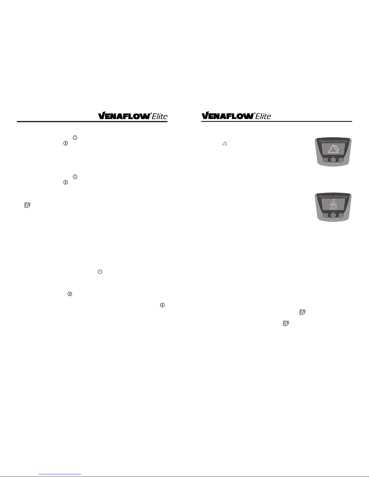
Aircast VenaFlow Elite User manual

30B101_C
Rx Only
DJO, LLC
1430 Decision Street • Vista, CA 92081-8553 • USA
t 800.336.6569 • f 800.936.6569
DJOglobal.com
Operator’s Manual
Prophylaxis for Deep Vein Thrombosis


1
Table of Contents
Design philosophy ................................................................ 2
Function .......................................................................... 2
Intended Use/Indications .......................................................... 3
Contraindications ................................................................. 3
Warnings and Precautions ......................................................... 3
Latex Information ................................................................. 3
General System Information and Application
Pump Features .................................................................... 4
Symbol Denitions ................................................................ 5
Pump Set-up ...................................................................... 6
Cu Application ................................................................... 7
Pump Operation................................................................... 8
Single Leg Operation .............................................................. 8
Patient Compliance Counter Reset ................................................. 8
System Alarms
Alarm Reset ....................................................................... 8
Tube Alarm........................................................................ 9
Single/Dual Leg Operation Alarm .................................................. 9
Compliance Alarm................................................................. 9
Call For Service Alarm.............................................................10
Battery Information and Operation
Battery Operation ................................................................10
Battery Charging Instructions .....................................................10
Low Battery Alarm................................................................10
Installing or Replacing Battery ....................................................11
Replacement Kit Instructions
Instructions for installing/removing/replacing the power cord .....................12
Bed Hanger Replacement.........................................................12
Instructions for replacing fuses....................................................12
Cleaning Instructions .............................................................13
Warranty .........................................................................13
Optional Alarm Verication Test ...................................................13
Ordering Information.............................................................14
Specications ....................................................................15
Customer Care Contact Information...............................................15

2
Design Philosophy
Pneumatic compression is a clinically proven modality for minimizing the risks
associated with deep vein thrombosis.¹ The Aircast VenaFlow Elite System leverages
the same clinically proven technology as the existing VenaFlow oering, but is
presented in a low prole, light-weight design. VenaFlow Elite combines two proven
technologies, rapid ination and graduated sequential compression, via our new
single tube Integrated Graduated Sequential Flow System (IGSF), to accelerate venous
velocity and enhance brinolysis. This unique combination makes VenaFlow the
only technology platform on the market that produces blood ows that mimic those
achieved through ambulation.² Additionally, VenaFlow Elite incorporates asymmetric
compression for the superior emptying of veins.³ The breathable and comfortable
VenaFlow Elite calf, foot and thigh cus enhance the patient experience, assist in
increasing compliance and are compatible with one universal pump.
Function
Once activated, the VenaFlow Elite system begins the compression cycle and inates
the cus one leg at a time, alternating between the two legs every 30 seconds. First
the distal aircell inates rapidly within less than .5 seconds, then the proximal aircell
follows. The distal pressure peaks at approximately 78 mmhg ± 15% and the proximal
pressure peaks at approximately 68 mmhg ±15%. These pressures then settle at
45mmhg ±15% and after 6 seconds, the cu deates. In 54 seconds, the ination cycle
begins again. An icon will appear on the graphical display signalling when the ination
cycle is in progress. (See‘Pump Features’ section) Pressure and the inate/deate cycle
are automatic and an alarm will be activated if the system is not functioning properly.
(See ‘System Alarms’section)
Pressure [mmHg]
Time [sec]
distal
VenaFlow Elite Calf Cu Pressure Curve
90
80
70
60
50
40
30
20
10
0
01 2 3 4 5 6 7
proximal
1. Labropoulos N, OH D.S, Golts, E, et al: Improved Venous Return By Elliptical, Sequential and Seamless Air-
cell Compression. Loyola University Medical Center, January 2003.
2. Whitelaw G, Oladipo O, Shah BP, et al: Evaluation of Pneumatic Compression Devices. Boston Orthopedics,
March 2001.
3. Kamm R: Unsteady Venous Blood Flow Resulting From Different Modes of External Compression Cambridge,
MIT, 1996
15
Specications
Size: 7.6”x 8.5”x 4.6”
Weight: no battery: 4 lbs. with battery: 4.75 lbs.
Power input: 100-240~, 50-60 Hz, 200 – 500 mA
Cord: Hospital grade, 15 ft
Standards: IEC 60601-1, IEC 60601-1-2
TUV Device Classication: Class 1 BF
Ination mode: rapid ination and graduated, sequential compression
Bed hanger: accommodates up to 3.5”
Battery: Li-ion polymer 11.1V, 4250 mAh
Fuse: 250V 2A IEC FA 5X20MM
Storage
Storage/Transportation Temperature: 0º C (32º F) to 50º C (122º F).
Operating Conditions
Operating Temperatures: 0º C (32º F) to 50º C (122º F)
Relative Humidity: 30% to 70%
Atmospheric Pressure: 650 mmhg to 790 mmhg
Customer Care Contact Information
Service: 800-336-6569 ext 5568
Technical support: 800-336-6569 ext 5566

3
Intended Use/Indications
The VenaFlow Elite System is intended as a prophylaxis for deep vein thrombosis
(DVT). The VenaFlow Elite System is designed to be used only with Aircast
VenaFlow Elite Compression Cus. Battery operation use only with DJO, LLC
battery packs.
Contraindications
The VenaFlow Elite System should not be used by persons with known or
suspected deep vein thrombosis, severe congestive heart failure, pulmonary
edema, thrombophlebitis, severe arteriosclerosis, or active infection. Do not
use on extremities which are not sensitive to pain, where cu will interfere with
gangrene, on patients with vein ligation or recent skin grafts, or extreme deformity
of the leg. Do not use the VenaFlow Elite System where increased venous or
lymphatic return is undesirable.
Warning and Precautions
• TheVenaFlowElitecusaredesignedforsinglepatientuseonly.
• Riskofexplosionifusedinthepresenceofammableanaesthetics.
• Theequipmentorsystemshouldnotbeusedadjacenttoorstackedwithother
equipmentand,ifadjacentorstackeduseisnecessary,theequipmentorsystem
should be observed to verify normal operation in the conguration in which it will
be used.
• MedicalElectricalEquipmentneedsspecialprecautionsregardingEMC.Portable
andMobileRFCommunicationsEquipmentcanbeaectedbyotherMedical
Electrical Devices.
• Cususedincombinationwithwarmingdevicesmaycauseskinirritation.
Regularlycheckforpatientcomfort,complianceandskinirritation.
• Specialattentionshouldbegiventothosepatientswithneuropathiesortissue
viability problems (i.e. diabetes, arterial or venous insuciencies).
• Topreventextremitycompartmentsyndrome,specialattentionshouldbegiven
to patients who are positioned in the supine lithotomy position for extended
lengths of time. This includes patients with or without compression cus.
• Ifyouexperiencepain,swelling,sensationchangesoranyunusualreactionswhile
using this device, consult your medical professional immediately.
Latex Information
All components of the VenaFlow Elite System are latex-free. All VenaFlow Elite
cus are latex free and may be placed directly against the skin or over a light
compression dressing.
14
System Replacement Parts
Part # Description
3070 Power Cord (U.S.), Hospital Grade
3071 Bed Hanger
3072 Tube Attachment Tag
3073 Fuse
3074 Battery Pack
Ordering Information
Systems:
Part # Description
30B VenaFlow Elite System
30B-B VenaFlow Elite System with Battery
30BI VenaFlow Elite System, International
30BI-B VenaFlow Elite System, International with Battery
Accessories:
Part # Description Qty Maximum Calf
Circumference
3040 VenaFlow Elite Calf Cu Pair 19”
3042 VenaFlow Elite XL Calf Cu Pair 22”
3043 VenaFlow Elite Bariatric Calf Cu Pair 30”
3045 VenaFlow Elite Thigh Cu Pair One size ts all
3046 VenaFlow Elite Foot Cu Pair One size ts all
3050 VenaFlow Elite Foam Calf Cu Pair 19”
3008 Tube Assembly, 5.5' Each
3008XL Tube Assembly, 8.5' Each
3008XXL Tube Assembly, 10.5' Each
3008XXXL Tube Assembly, 12.5' Each

13
Cleaning Instructions
The tube assembly is reusable. Both the pump case and the tube assembly can be
cleaned with mild soap solution, antiseptic or disinfectant wipes. Avoid excessive uids
over the top of the system. Do not submerge.
Warranty
DJO, LLC will repair or replace all or part of the 30B or 30B-B system for material or
workmanship defects for the lifetime of the system, excluding battery packs.
DJO will repair or replace all or part of the cus, tube units and battery packs for
material or workmanship defects, not including normal depreciation of battery life or
charge capacity, for a period of six months from the date of sale.
Optional Tube Alarm Verication Test
The Tube Alarm Verication Test is provided for facility verication purposes only and is
not required prior to use.
Attach tube assembly to pump and connect power cord to electrical outlet. Simulate
a kinked tube situation by folding the tube over onto itself once and holding it for 4-6
minutes. The second cycle after the simulated kink should activate an audible alarm
and this symbol will appear with“CHECK TUBES”on the graphical display and the
pump indicator lights on the side of the system will ash red.
4
Bed hanger release
Graphical display
Pump indicator lights
Telescoping bed hanger
Pump Features
Single / Dual Leg
operation indicator
Battery indicator
* Note: not all VenaFlow Elite
Systems will contain a battery
Single/Dual leg
operation push button
ON/OFF/RESET push
button
Ination cycle
indicator
First 3 minutes (ramp
up) indicator
Patient compliance
counter
Patient compliance
counter reset push
button
00 : 03: 06

5
Symbol Denitions
Power on/o button and alarm reset
Dual or Single leg operation
Compliance monitor reset
Tube alarm
Call for service
Ination cycle indication (Bars indicate cus are inating)
See VenaFlow Elite System operator’s manual
Safety classication: Class 1 BF
250V 2A IEC FA 5X20MM
Battery
Separate collection for electrical and electronic equipment. Remove and dispose of
batteries in accordance with local or national requirements.
12
Replacement Kit Instructions
Replacement kits may be ordered through customer care.
Instructions for installing/removing/
replacing the power cord.
1) Make sure system is powered o and unplugged.
2) Remove the screw retaining the power cord cover
using a 1/16”hex driver.
3) Remove the power cord cover.
4) Remove the power cord.
5) Install new power cord and reassemble power cord
cover.
Telescoping Bed Hanger Replacement
1) The telescoping bed hanger piece can be
removed and replaced if necessary.
2) To replace the bed hanger, hold down release
button on the back of the system and rmly pull
bed hanger out of the body of the system.
3) Discard the broken or ineective hanger. To
install the new bed hanger, slide the new hanger
back into the body of the device and set at
desired length.
Instructions for replacing fuses
1) Remove the power cord. Refer to the ‘Instructions for
installing/removing/replacing the power cord’ section.
2) Remove fuse holder from power entry module.
3) Remove fuses from fuse holder.
4) Replace any blown fuses with 250V, 2A, IEC fast acting
5X20mm fuses.
5) Reassemble fuse holder and replace power cord per
previous instructions.

11
Low Battery Alarm
1) When there is approximately 15 minutes of charge left in the
battery, an audible alarm will beep 3 times every minute.
When there is less than approximately 5 minutes of charge
left, a consistent beep will sound and a larger version of the
battery icon will appear on the graphical display and it will
alternate with the text“LOW BATTERY”.
2) When either battery alarm occurs, immediately plug device in to electrical outlet
to begin replenishing the charge.
3) If the device is not plugged in during the alarm period, the device will shut down
and will fail to power on again until the device is plugged in again.
Installing or Replacing the Battery
1) Remove power cord. Refer to the ‘Instructions for
installing/removing/replacing the power cord’ section.
2) Remove back cover of device by removing 4 screws
using TORX (star) T20 driver.
3)
Remove power supply connector from board connector J4.
4) Install battery into the device below the reservoir.
5) Attach power supply connector to battery connector #1.
6) Attach battery connector #2 to J4 connector on board.
7) Attach battery connector #3 to J2 connector on board.
8) Close back cover of device and fasten
screws.
9) Reinstall the power cord and power
cord cover per previous instructions.
10) Plug in the system.
11) Hold down single/dual leg operation
button and then press the power
button to turn on the system. LCD
back light will turn on, with blank
LCD.
12) Release the single/dual leg operation
button.
13) Press and release counter reset
button.
14) Turn o the system by pressing the
power button. Battery will be congured at this point.
15) Turn on the system. After the cu detection cycle, the system should display a
battery icon on the right hand side of the LCD.
16) Leave the device plugged in for at least 4 hours to allow battery to charge. The
battery will charge whether the system is turned on or o.
1
2
3
J4
J2
6
Pump Set-up
1) Hang pump from bed frame (foot of
bed), bed rail, or rest on oor or table.
To use the telescoping bed hanger,
press release button on the back of the
device and gently pull out bed hook to
the desired width.
2) Connect tube assembly to the pump.
Make sure tubing connectors lock
securely into pump connectors.
3) Plug in the power cord to electrical
outlet.

7
Cu Application
The VenaFlow Elite System will automatically detect the cu that is attached to the
device and apply appropriate pressures.
1) Calf cu – Apply cu with the aircell centered on back of leg and with the tube
pointed toward the foot.
Foot cu – Apply cu with the aircell centered on bottom of foot and with the
tube pointed to the left
Thigh cu – Apply cu with the distal aircell centered on back of calf and proximal
aircell centered on back of thigh with the tube pointed toward the foot.
2) Connect cus to the tubing that is attached to the pump.
For varied patient sizes, trim calf and thigh cus as needed for proper t.
Be sure to secure cu straps snug but not tight. When using the calf cu and thigh cu,
rotation of the aircell on the leg does not aect performance of the system.
10
Compliance Alarm
1) If the cus are removed from the patient while the device
is still functioning and the cus are not reapplied after 15
minutes, a visual alarm will ash and the graphical display
will read“COMPLIANCE ALARM”. Additionally, the pump
indicator lights on the side of the system will ash red.
2) Reset alarm rst, and then reapply cus. You must reapply
the cus within 9-15 minutes after resetting the alarm in order to prevent another
compliance alarm from occurring.
3) If cus are reapplied without resetting the alarm, the compliance alarm will
automatically reset after 9-15 minutes
Call For Service Alarm
1) If one of the system’s critical components is not working
properly, the Call For Service alarm symbol will appear on
the graphical display and it will alternate with the text “CALL
FOR SERVICE”. Additionally, the pump indicator lights on the
side of the system will ash red.
2) If Call For Service alarm occurs, unplug the device and call
DJO Technical support at 800-336-6569 extension 5566 for further instructions.
Battery Operation
The VenaFlow Elite can be installed with a battery upon request at the time of the
initial system order. When the battery-installed system is powered on, this battery icon
will appear on the right side of the graphical display beneath the single/dual leg mode
icon. If the system does not have a battery installed, then there will be no battery
icon on the graphical display at all. When the system with battery is unplugged and
powered on, the system will automatically switch to battery power.
The battery must be charged before use. Once a system has been congured to run
with a battery, it must always have a battery installed. Otherwise a 'LOW BATTERY'
alarm will continuously occur. See 'Specications' section for battery pack information.
Battery Charging Instructions
1) To charge the battery, simply plug in the system to an electrical outlet either while
the system is on and functioning, or when it is powered o. The system will begin
charging immediately after being plugged in.
2) The VenaFlow Elite System with a fully charged battery will last for approximately
2 hours. It takes an estimated 2 hours to fully charge the battery when the unit is
o. When the unit is on, it takes an estimated 4 hours to charge the battery.
COMPLIANCE
ALARM

9
Tube Alarm
1) If one or both tubes has a kink or leak, after 4-6 minutes this
symbol and the text “CHECK TUBES”will alternate on the
graphical display, an audible alarm will sound and the pump
indicator lights on the side of the system will ash red.
2) If a tube alarm occurs, ensure that the tube connections
are secure and that the tubing is kink-free. Check pump
connectors and tubing/cu connectors for cracks or damage. Reset alarm.
3) If alarm occurs again, replace cus and tubing altogether.
Single/Dual Leg Operation Alarm
1) Once powered on, the VenaFlow Elite System will default to
dual leg operation mode. In the event that the selected leg
operation mode and the number of cus attached do not
match, after 4 minutes, an audible alarm will sound and this
symbol will appear on the graphical display along with the
text,“LEG ALARM”. Additionally, the pump indicator lights on
the side of the system will ash red.
2) A leg alarm will occur if either of the following occur:
- Single leg use is desired, one cu is connected, but the single leg operation
button is not pressed within 3 minutes after powering on the device.
- Single leg operation button was pressed within 3 minutes of powering on the
device, but two cus are connected.
3) When a single/dual operation“LEG ALARM”occurs, reset alarm, and then ensure
that the icon at the top right corner of the graphical display is consistent with the
number of cus that are connected to the tubing and adjust accordingly.
Enabling Compliance Alarm
A compliance alarm can be enabled on the device as an option. To enable compliance
feature, complete the following steps:
1) Start with the system powered o.
2) Press and hold the single/dual leg operation button and while holding, press
the power button . The graphical display screen will go blank with no backlight.
3) Press the single/dual leg operation button .
4) Select button underneath ‘Change’.
5) Select button underneath ‘Other’.
6) Select button under ‘No alarm’.
7) Select the button under ‘Done’ to set the new conguration. The change is
complete and the system is ready to operate.
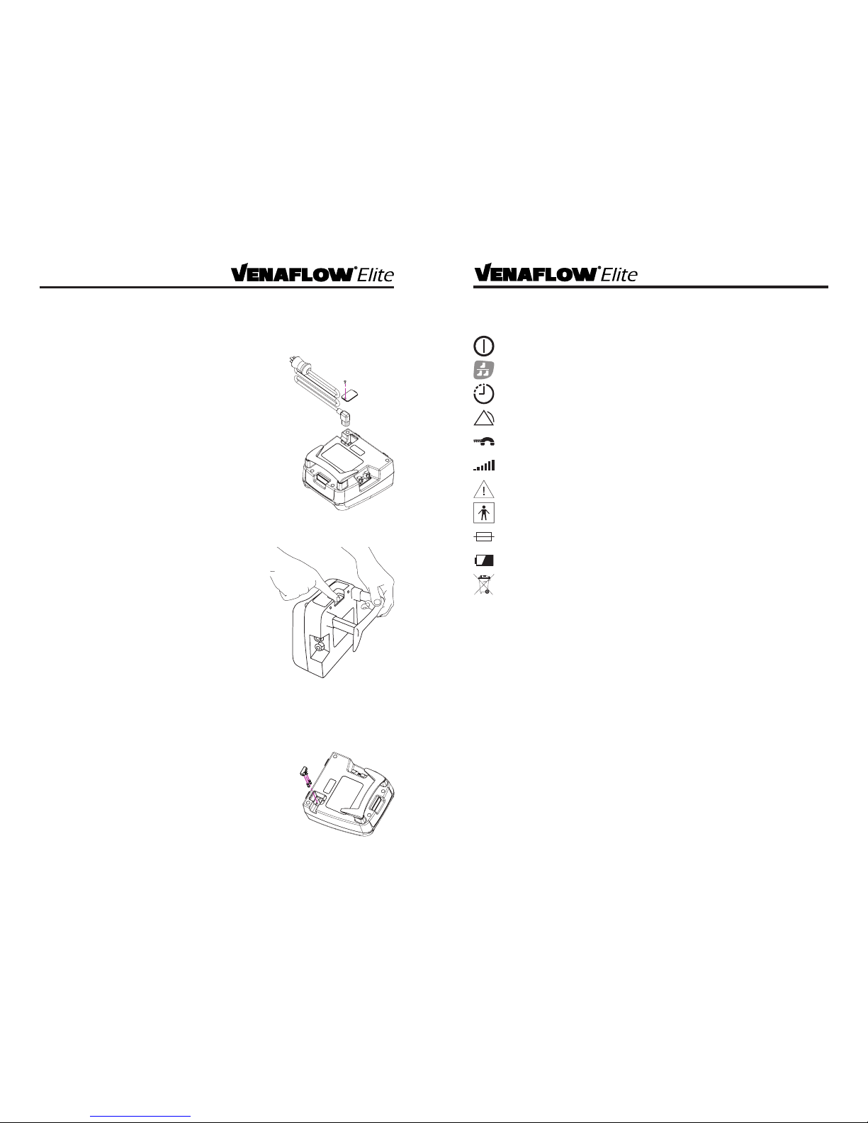
8
Pump Operation
1) To turn the device on, press . The graphical display, green pump indicator lights
and green light above button will turn on.
2) Once device is powered on, system will immediately enter cu detection mode
which means the system will be detecting whether or not there are cus attached.
Display will read“DETECTING CUFF” and will display percentage of detection
complete. Once it reaches 100%, the display will then transition to the standard
display screen.
3) To turn the device o, press . The graphical display, green pump indicator lights
and green light above button will turn o.
Single Leg Operation
1) After system is turned on, within 3 minutes push the single leg operation button
to indicate that single leg use is desired. The single leg icon will appear at the
top right corner of the graphical display.
2) If the single leg operation mode is not selected within 3 minutes of the system
powering up and only one cu is connected, the“LEG ALARM” will be activated.
3) If the single leg operation mode is selected within 3 minutes of powering on and
two cus are connected instead of one, a“LEG ALARM” will be activated.
4) In single leg operation mode, the device inates detected cu every minute for 6
seconds.
5) Either port may be used for single leg operation. The system will automatically
detect which one is in use.
Patient Compliance Counter Reset
To reset the patient compliance counter, press for 1 second and release. The hours,
minutes and seconds will reset.
Alarm Reset
To reset any alarm, press the button and take steps to correct the alarm if
necessary. To change from dual to single leg or single to dual leg operation mode
after the 3 minute ramp up period or after ramp up indicator disappears, press the
button to turn o the device, then again to power on again. The device will go into
ramp up mode and user will have 3 minutes to change the dual leg operation to single
leg mode.
Other manuals for VenaFlow Elite
2
Table of contents
Other Aircast Medical Equipment manuals
Popular Medical Equipment manuals by other brands

Albrecht
Albrecht CDS ANKLE BRACE User instructions

Little Doctor
Little Doctor LD Cardio instruction manual

Covita
Covita Smokerlyzer Micro+ Calibration guide

Hollywog
Hollywog WiTouch Pro TENS user manual

GE Medical Systems
GE Medical Systems LOGIQ 500 quick start guide

Siemens
Siemens SIREMOBIL Iso-C Installation and setting instructions

Clevemed
Clevemed BioRadio 150 user guide

Gima
Gima 27403 User manual and assembly instructions

FIOR & GENTZ
FIOR & GENTZ NEURO SWING H2O Instructions for use

Performance Health
Performance Health Core:Tx user guide

Tuffcare
Tuffcare T4000 Installation and operating instructions

Dr. Mach
Dr. Mach Trigenflex R96 Directions for use