Airflow DUPLEXVENT DV72 R Manual

1
Commissioning Data:
to be completed by the installer
Date of installation:
Configuration Left Hand Right Hand
Product Serial No:
90
0
00556/
90000557
–
Issue 9 10/15
Important:
This multi speed unit required Air Flow Rates to be adjusted when system is commissioned.
This manual must be kept by the householder
MODEL: DV72 R & L
Mechanical Ventilation with Heat Recovery
Installation Instructions and User Manual

2
Index
Page
General Information 3
About the Unit 4
Wiring Diagram 5
Technical Specifications 6
Installation Instructions 7 - 15
Commissioning 16
Check List 17
Maintenance 18 – 19
SAP Appendix Q Testing Results 20 – 22
Declaration of Conformity 23
Warranty 24

3
General Information
To maintain a healthy indoor environment, closely controlled ventilation is essential. There are
many pollutants that will affect the indoor air quality: human body waste products in the shape of
CO2, dead skin, perspiration and moisture. Add to this the waste products of cooking (cooking
smells), showering (moisture), gases from building materials and the waste products of pets.
Without proper ventilation this would be the perfect environment for the growth of mould,
subsequent damage to the decoration and fabric of a home and to the health of its occupants.
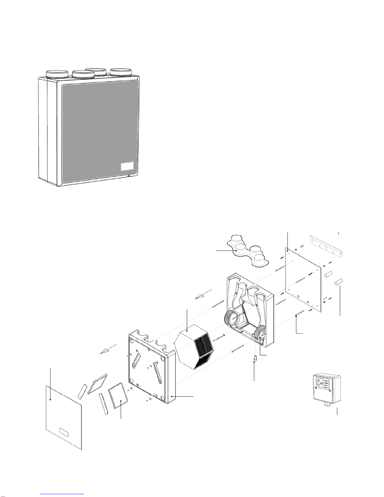
The Heat Recovery unit is fitted with two, low energy EC fans with a constant (100% adjustable) air
volume.
The exhaust fan ensures that warm, damp and polluted air as near as possible to the source is
extracted. The exhausted air has to be replaced with fresh air, so the heat recovery unit not only
has an exhaust fan, but is also fitted with a supply fan and air filters.
The supply air, which in winter is colder than the inside air, is heated in the heat recovery unit using
the heat of the exhaust air by means of the heat exchanger. This heat exchanger has a maximum
efficiency of 91%, so a minimum loss of heat takes place and the supply air temperature enters the
home at a comfortable level.
In exceptionally cold weather or winter conditions it is possible that the exchanger may freeze due
to sub-zero, cold incoming air. Therefore the unit must be sited in a frost-free location.
Alternatively, an in-duct heater may be used to protect the heat exchanger from freezing.
The filters in the unit ensure that the fresh supply air is clean as it enters the home. Also, the
extract air from the property is filtered to protect the heat exchanger from unwanted contamination.
These filters must be inspected regularly, initially every month, and cleaned. Each property will
contaminate the filters at a different rate. The filters should be replaced annually or after a
maximum of two cleaning cycles. Regular filter maintenance will ensure the integrity and
performance of the unit.
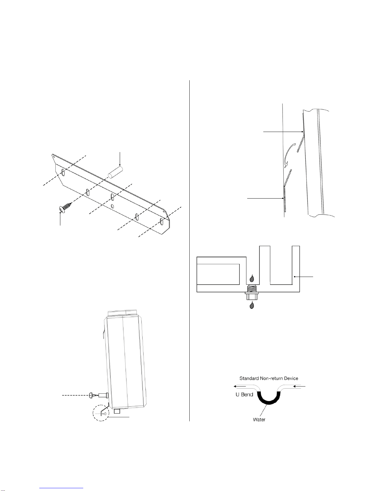
The unit’s condensate drain must be installed and connected to the household drainage system
and must be insulated if installed outside the insulated envelope of the building
If the ductwork passes through an unheated area (loft or similar location), it must be insulated with
an insulation material that complies with the latest Building Regulations.
DO NOT switch off the unit – it is designed to run continuously. If the unit is switched off,
indoor pollutants and moisture levels may increase which could endanger your health or
damage your home.
In the event of a power failure or the unit being turned off, restart the unit at High Speed.
This MVHR unit has a soft start.
It is important to follow the advice in this user manual and correctly maintain the system to
ensure a healthy indoor environment.

4
About The Unit
Mounting
plate
W
all
bracket
EXPLODED VIEW
Spigot
Heat recovery cell
Spacers
Fixing rods
Motor assembly
Front cover
Drain
Front shell
Remote control
Filter & Filter plugs
Duplexvent DV72 R & L are complete heat recovery
units to ensure optimum efficiency for your home.
The units are supplied as left or right hand options.
See page 11
Standard wall mounting kit is supplied with each unit.
For fitting see page 9-12. Optional horizontal floor
mounting is also available.
See pages 13-15
The units are supplied as standard with:
Frost protection, boost function, thermal bypass and
remote commissioning panel.

5
Wiring Diagram
Commissioning – Electrical connections.
1. All wiring must conform to BS 7671 : Latest edition IEE wiring regulations.
2. his appliance is suitable for 230V
~
50Hz single phase supply fused at
3 amp
.
3. he appliance must be earthed and a double pole switch having a minimum contact separation of 3.0mm
must be used to provide isolation for the unit.
4. he unit is supplied with a 1.5 meter long, 8 core cable for remote control connection. here is a risk that a
longer cable may act as an aerial causing electronic interference problem to the unit. ( 8 Core Signal Cable –
0.22CSA – Non Shielded ).
Remote Control Cable Connections.
5. Four core mains supply cable minimum size 0.75CSA.
6. Upon Installation the fans should be started in High Speed mode to ensure optimum performance of fans
and then adjusted to the required continuous ventilation setting.
7. he remote controller must not be mounted above or within 1 meter of a cooker where it could be affected
by excessive heat or moisture.
Emergency
shutdown
details
-
Unit
to
be
isolated

6
T
echnical
Specifications
Spigot Ø
125mm
Commutated DC)
Duplexvent Static Pressure
-
Airflow
Maximum Flow Rate 75 l/s (270m3/h) MAX* Protection Class IPX2
G3
Fans EC (Electronically
Max Power Consumption 140W Weight 14kg
560 x 635 x 260mm
Dimensions230V/1PH/50HzElectrical Supply
G3
Supply Filter
Extract Filter
Counter Flow (Plastic)
Thermal Efficiency ≤91%
Heat Exchanger

7
Installation
Instructions
IMPO
R
T
ANT
Be sure to have read and understood
SAFETY
AND RECOMMEND
A
TIONS
•
All
wiring
must
comply
with
Building
Regulations and the current I.E.E.
Wiring
Regulations (BS7671) or the equivalent
standards for your country. The final
installation should be examined and
tested by a qualified electrician.
Precautions must be taken to avoid the
back-flow of gases into the dwelling
from
the open flue of gas or other fuel-
burning
appliances.
Make sure the mains supply complies
withtheratinglabelforvoltage,
frequency
and phase.
these
instructions
before
beginning the
installation process.
PRE
-
INS
T
ALL
A
TION CHECK LIST
Make sure that the unit can physically fit
in to the desired location.
The Duplexvent unit should be situated so
that access for maintenance or
replacement of parts and filters is
possible.
The Duplexvent unit is suitable for
conventional rigid ducting or low energy
radial duct system – Airflow Development
Airflex Pro system. If using conventional
ducting ensure duct runs are as short as
possible, having the most direct route and
using as few bends as possible. This is to
reduce system pressure.
•
•
•
Childrenshallnotplaywiththe
appliance.
Cleaning and user maintenance shall
notbe made by children without
supervision.
If any cables are damaged they must be
replaced by the manufacturer, its service
agent or similarly qualified persons
•

8
Installation Instructions
Control Options
Frost Protection
When
the
cell
temperature in the
unit
falls
below 3ºC the unit automatically warms the
cell with extracted air to prevent the formation
of frost.
Boost
-
Switch
ed
Live
The
unit
comes
with
Switch
ed
Live
as
standard. It is an automatic function, sending
the unit to boost when the bathroom or kitchen
light is on, or boost switch is activated.
Summer Bypass
The
summer
bypass
helps
reduce
the
air temperature coming into the dwelling
during the summer months. It is an automatic
function and operates when the supply air
temperature to the property is above 25ºC.
Control Options
Frost Protection
Boost Switched Live
Thermal Bypass

9
Installation Instructions
FIRST
FIX
-
Installing ductwork and electrical supply
Important note: This unit is for wall or floor mount only. Ceiling mounting unit are
configured differently and should be ordered separately.
1. Locate external terminations (supply and extract) in accordance with the latest
addition
of the Domestic Ventilation Compliance Guide.
2. Ductwork from the unit is Ø125mm dia. - maximise duct size where possible. Make
sure that the ductwork is insulated in unheated spaces. Minimise flexible duct.
3. Locate the mains supply within 1m of the location of unit. The position of the
electrical
power supply or unit (a fused switched isolator) must not be mounted above or closer
than 1m to a cooker where it could be affected by excessive heat or moisture.
4. Make sure that there is room for the MVHR unit. The unit is designed to be wall
mounted. It can also be floor mounted with an additional kit. Part number 90000558
5. Also make sure that there is a free space at the front of the appliance for cleaning
the
filter and carrying out maintenance on the appliance.
Ducting Configuration
See page 11-15 for duct
connections
to the unit/air flow directions
Installed example, RH unit shown.
A– No exhaust within 2m of air inlet
B – Inlet duct from atmosphere
C – Outlet duct to atmosphere
D – MVHR
E – Ducts to and from property
F – Condense Drain
Note: Important – if installed in a loft space the area should be within the insulated
envelope to maintain optimum performance
Radial Duct System

10
Installation Instructions
SECOND FIX
–
Installing Vertically Hung unit
1. Attach the wall bracket to a flat stable
surface that is capable of bearing the
unit’s weight, 12Kg. Ensure that the
bracket is positioned so that there is
enough spaceforthecondensatedrainand
ducts to be connected. Fixing kit provided.
3.
Slide
the
unit
onto
the
wall
bracket
and
attach ducting and drain.
Pre fixed bracket
on the back of the
Duplexvent unit
Raw
Plugs x 5
W
all bracket
Screws x 5
Connect 22mm PVC drain fitting
2.
Attach
spacers
x
2
with
screws
provided.
The spacers ensure that the unit tilts
forward to improve drainage. Use
the
tie down cable if required to secured
the
bottom of the unit.
Anti – Vibration Mount
Foam
casing
4.
The
drainage
from
the
unit may
be
connected
to
an
internal
waste
water system or soil pipe with an
appropriate non-return device. One way
valve device is recommended. Insulate
pipes in an unheated loft space.
Wall fit only

11
Installation Instructions
SECOND FIX
–
installing Vertically Hung Unit
Airflow and drain fitting - LH
Airflow
and
drain
fitting
-
RH
Drains are factory fitted.
The units has either a LH or RH drain.
T
o atmosphere
From atmosphere
Extract from dwelling
Supply to dwelling
Supply to dwelling
Extract from dwelling
From atmosphere
T
o atmosphere
W
all
mount
W
all
mount

12
Wall mounting bracket dimensions
Please note that there is only one loose bracket with the two tab bracket
factory fitted.
Picture of “ ie Down Cable”.

13
Horizontal mounting bracket dimensions

14
up).
Installation Instructions
SECOND FIX
–
Installing Horizontal Mounted Unit
Connect 22mm PVC drain fitting
Floor mounting
5.
6.
Mount
the remote control near the unit.
Fix
securely
to
a
flat
surface.
For
maintenance please ensure the remote
control is disconnected before
removing
the unit from the wall.
Th
e
uni
t
ca
n
b
e
floo
r
mounted by using
the horizontal mounting kit,
Part Number 90000558
Use the long and short S brackets
provided along with short fitting screws
to ensure correct drainage. The unit must
be higher at the duct end.
Bracket fixing position. See Page 13
Drain
connections
should
be
solvent
welded as here. The center Tee section is
reversed to make either LH or RH
drain. Push in the drain fitting and seal
as appropriate to create a watertight
assembly.
Whe
n
fixin
g
th
e
remote control
pleas
e
ensure the ribbon cable is in place
(contacts down, red side up)
RH
LH
Important note: The floor mounted drain
must be fitted on the same side as the factory
fitted drain. This unit is for wall or floor mount
only. Ceiling mounting units are configured
differently and should be ordered separately.
X2
X2

15
Installation
Instructions
SECOND FIX
-
Drainage for floor mounted units
Floor mount
-
LH drain
Floor mount
-
RH drain
T
o atmosphere
Extract from dwelling
From atmosphere
Supply to dwelling
T
o atmosphere
Extract from dwelling
From atmosphere
Supply to dwelling
Place stopper
provided into the
fitted drain
Place stopper
provided into the
fitted drain
Ø20mm Saw
Ø20mm Saw
Drill into the case as shown, using the metal plate
as a guide. Ensure that the foam core is fully removed.

16
Commissioning
Setup guide for the Duplexvent
The
commissioning
the remote switch.
panel
is
found
on
the
Commissioning
mode
is
chosen
by
pressing
the SET button for 4 seconds, all
sensor
inputs will be disabled in this mode so that
theydonotinterferewithflowrates.All
LEDs
will light with the Extract Boost
flashing
(Ext B), this indicates that the flow rate
may
now be increased/decreased as required.
The next press of the SET button will
move
commissioning to the next setting, Sup.B
and so on. When the unit has been fully
commissioned, press the SET button for
4
seconds and this will put the unit back into
status mode. If the unit
is not put back into
status mode after commissioning, it
will
automatically
revert back to status mode
after an hour.
Note: Settings will be retained if the power
supply is interrupted.
switched input ON
LED Indications
Constant LED Flashing LED
(A) Frost protection ON
(B) Boost state -
Humidity ON (A) Service required
(C) Boost state - (B) Service required
(D) Summer by-pass
ON
Supply and extract LED indications
Commissioning mode only

17
Checklist
•
Installation instructions have been understood
• Ducting Ø125mm or larger has been used from the unit
• The unit is securely fixed into position with enough space left for servicing
• Condense drain is tight, drains to a suitable location and has been water tested

18
Maintenance
Pack of 2 x filters.
Par
t number
9041511
Filter cover
Front cover
General advice:
Regular filter inspection is recommended. Minimum recommendation is to check filters
every 6 months. Some installations will need more frequent filter inspection to ensure
maximum efficiency of unit.
Filter Maintenance recommendation:
1.
2.
3.
4.
5.
6.
7.
Switch o
f
f the power supply
Remove front panel
Remove filter covers
Remove the filters
Vacuum the outside of the filter or replace if required
After cleaning replace filters at same side
Replace filter covers and front panel
Major service:
This is to be carried out every five years (minimum) by an approved maintenance
company.

19
Maintenance
Disassembly of unit for engineering access and
maintenance:
1.
Remove
the
velcro pads.
front
cove
r
...held
on
with
3.
Carefully remove the top foam
moulding by pulling it straight forward.
Foam mouldings must remain parallel.
T
ake
care
gaskets.
not
to
damage
the
sealing
2.
Remove
retaining
screws
and
washers
x 4, store safely.
Do
not
pull
from
one
edge
as
this
may
damage the internal fixing rods.
When reassembling the unit should be, after maintenance, ensure there are no
trapped wires and that seals are intact.

20
SAP Appendix Q Testing Results
Central mechanical supply and exhaust ventilation system packages with
heat recovery used in a single dwelling
Brand Name Airflow
Model Duplexvent DV72R and DV72L
Model Qualifier (if applicable)
Current Manufacturer
and Contact Details
Name Airflow Developments Ltd
Address
Lancaster Road
Cressex Business Park
High Wycombe
HP12 3QP
Telephone
01494 525252
Website www.airflow.com
Original Manufacturer (if different)
First Year of Manufacture 2015
Last Year of Manufacture
Testing Body BRE
Date of test 22/03/2010
Serial Number of Product Tested 5780 EC
MVHR to outside grille duct types and size
150 & 125 mm diameter rigid plastic and
200 mm diameter rigid plastic
Duct types and sizes used for supply and
exhaust 150 & 125 mm diameter rigid plastic and
200 mm diameter rigid plastic
Results of leakage tests
Table Q1
Internal Pass
External Pass
This manual suits for next models
1
Table of contents
Other Airflow Ventilation manuals