Airflow Duplexvent Flexi DV1100 User manual

Installation, use and
maintenance manual
for
Duplexvent Flexi
DV1100,1600, 2600, 3600

2
Dear customer,
Thank you for choosing our product and we hope that you will be fully satisfied.
This manual contains all necessary instructions, information, hints and recommendations for safe and correct equipment installation
and commissioning. Please read the manual carefully and follow the instructions contained herein.
Symbols explained
Items or sections marked with ( or with a grey background) apply only to appliances manufactured in compliance with the hygienic
requirements of Regulation VDI 6022 (indicated on the identification plate, see following chapters).
Important notices
●Electrical connections, commissioning and adjustment of the appliance may only be carried out by qualified electrical
engineers.
●Before the installation and commissioning of the appliance carefully read the installation, use and maintenance
manual, the controller operation manual and, where applicable, the service documentation.
●The appliance and all its accessories must be installed and used in compliance with the design, technical conditions
specified by the manufacturer and applicable legislation and technical standards in effect.
●The appliance may not be installed and operated in an aggressive environment that could damage its external and
internal mechanical parts.
●Before putting the appliance into permanent operation an initial inspection report on the appliance´s power supply
must be provided.
Before putting the appliance into operation an approval test (see VDI 2079 and DIN EN V 12599) of the entire HVAC
system of which the appliance forms part must be conducted. The test must include the examination of hygienic
requirements as per VDI 6022 and must be documented. The user must be able to present the approval test report at any
time. If the above requirements are not met, the manufacturer cannot ensure compliance with hygienic requirements.
The manufacturer is not liable for damage caused by unprofessional installation and operation that
is not in compliance with the operation and maintenance manual and general practices applied
during installation and operation of HVAC equipment and control systems.

3
1. Content
1. Content ........................................................................................................................................................................................3
2. Safety instructions........................................................................................................................................................................4
2.1 General safety...............................................................................................................................................................................4
2.2 Operational safety .........................................................................................................................................................................4
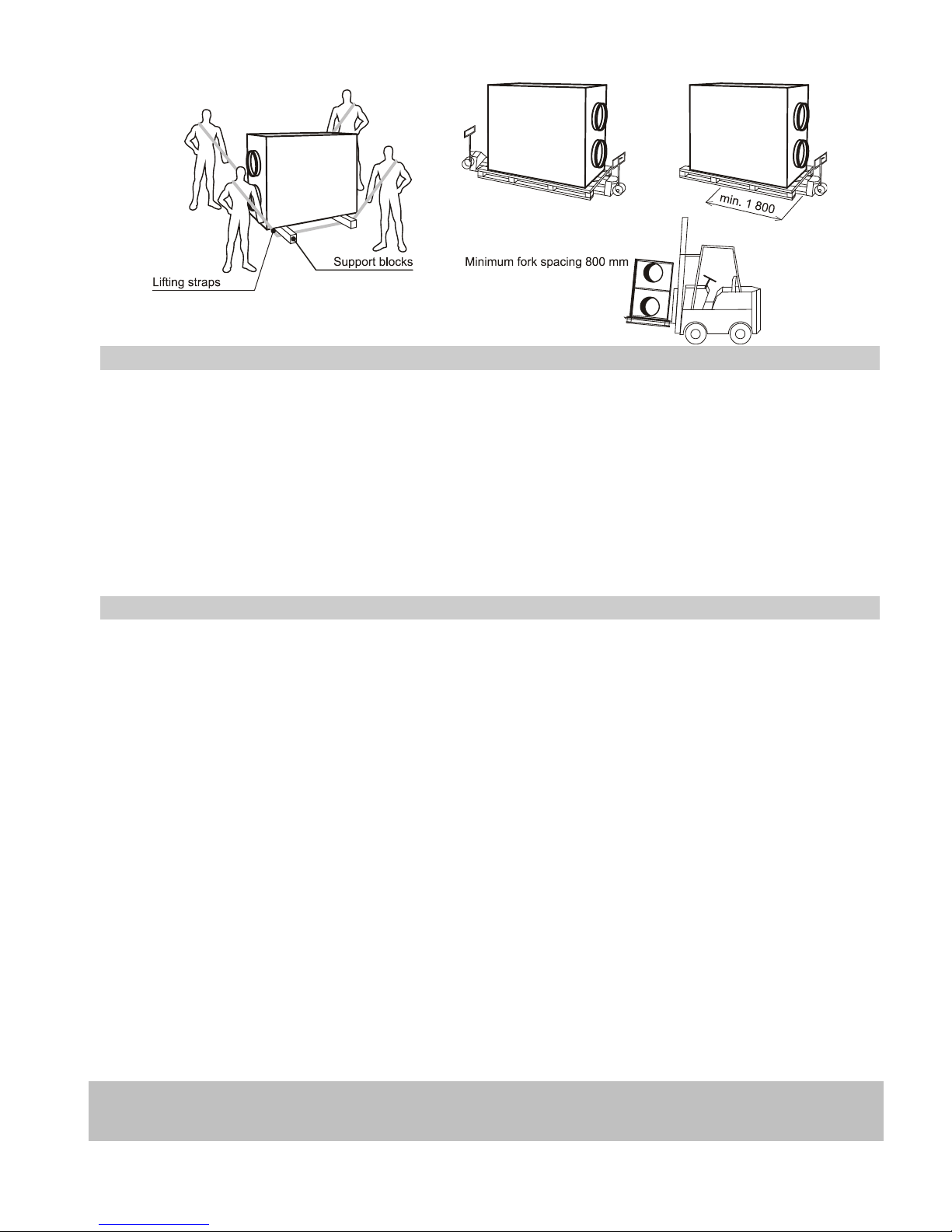
3. Storage and transport ..................................................................................................................................................................4
4. Description ...................................................................................................................................................................................5
4.1 General .........................................................................................................................................................................................5
4.2 Intended use .................................................................................................................................................................................5
5. Installation....................................................................................................................................................................................5
5.1 Safety instructions.........................................................................................................................................................................5
5.2 Hygienic instructions for the appliance as per VDI 6022 ...............................................................................................................5
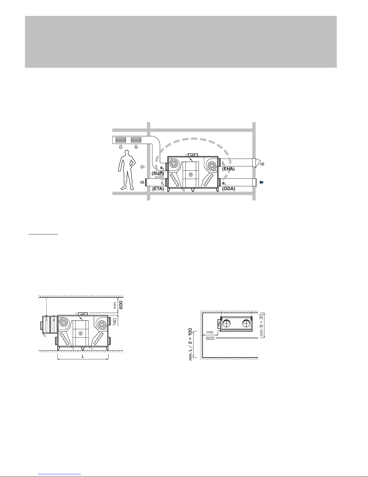
5.3 Identification of ports, connecting the HVAC duct .........................................................................................................................6
5.4 Installation steps ...........................................................................................................................................................................6
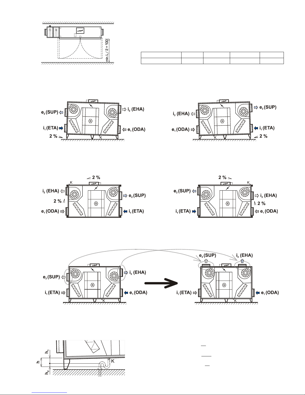
5.5 Adjusting the unit - turning ports e2 (SUP) / i2 (EHA)....................................................................................................................7
5.6 Connecting the condensate drain pipe ..........................................................................................................................................7
5.7 Classification of air filters...............................................................................................................................................................8
5.8 Installing air filters..........................................................................................................................................................................8
5.9 Installation, connecting and filling of liquid manometers (optional accessory)...............................................................................9
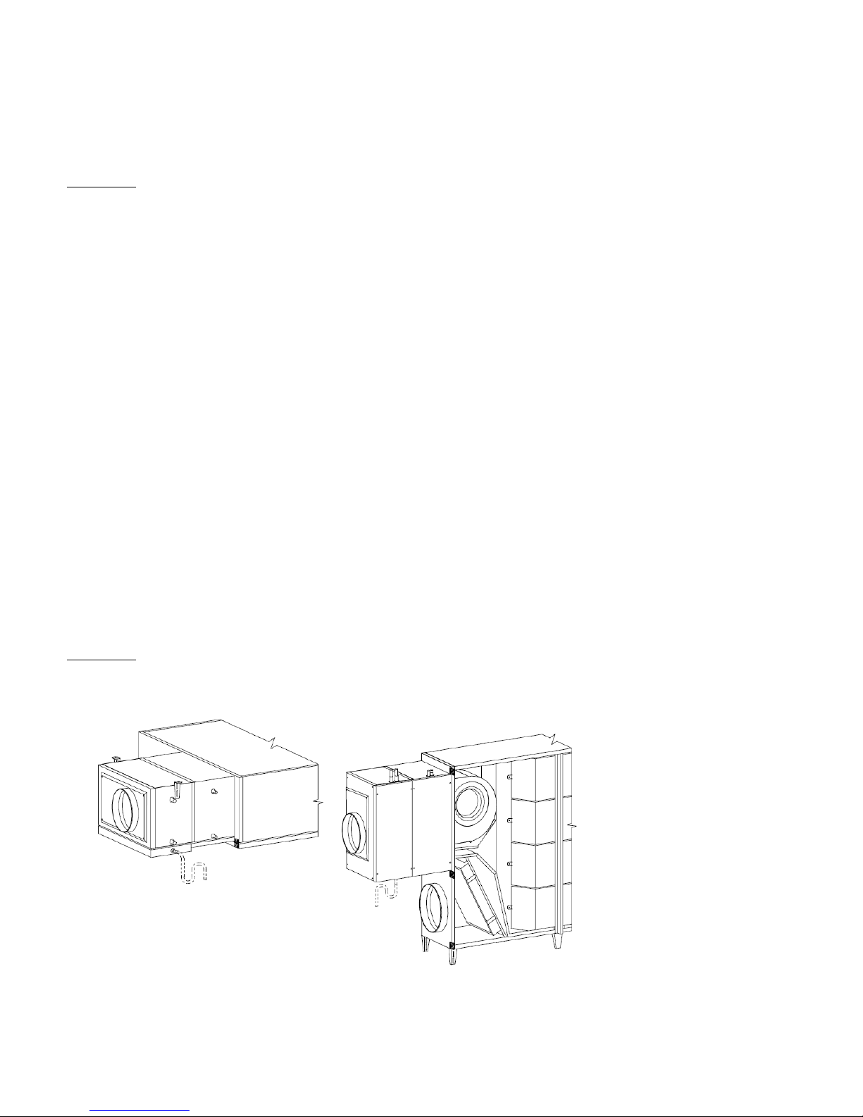
5.10 Installation and connecting of the hot water air heater (optional accessory) .............................................................................10
5.11 Installation and connecting of the control set of the hot water air heater (optional accessory) ..................................................10
5.12 Installation and connecting of shut-off dampers e1, i1 (optional accessory) .............................................................................10
5.13 Installation of flexible flanges (optional accessory) ...................................................................................................................10
5.14 Installation and connecting of the water chiller to the cool source (optional accessory)............................................................10
5.15 Installation and connection of the control manifold of the water-cooled chiller (optional accessory) .........................................11
5.16 Installation and connecting of the direct chiller (optional accessory).........................................................................................11
5.17 Installation and connecting of the electric heater / pre-heater EPO-V (optional accessory) ......................................................11
5.18 Installation and connecting of manostats to control constant flow rates and pressure (optional accessory) .............................11
6. Electrical connection, commissioning, description of controls....................................................................................................11
7. Hygienic instructions for the appliance as per VDI 6022 ............................................................................................................12
7.1 General instructions ....................................................................................................................................................................12
7.2 Required qualifications of personnel as per the type of activity...................................................................................................12
8. Inspecting the appliance ............................................................................................................................................................13
8.1 Overview of inspections and measures to ensure compliance with hygiene requirements .........................................................13
9. Cleaning and maintenance ........................................................................................................................................................14
9.1 General .......................................................................................................................................................................................14
9.2 Cleaning the cabinet....................................................................................................................................................................14
9.3 Air filters, replacing filter cassettes ..............................................................................................................................................14
9.4 Cleaning heat exchangers (heater / chiller).................................................................................................................................15
9.5 Cleaning the plastic heat recovery exchanger.............................................................................................................................15
9.6 Draining and inspection of the condensate collection tank (not included in delivery) ..................................................................15
9.7 Other minor maintenance............................................................................................................................................................15
10. Failures and troubleshooting......................................................................................................................................................15
11. Repairs, spare parts...................................................................................................................................................................16
12. Warranty.....................................................................................................................................................................................16
13. Visual appendix - manuals .........................................................................................................................................................17
13.1 Connecting the condensate drain line .......................................................................................................................................17
13.2 Rotating the fan.........................................................................................................................................................................18
13.3 Fitting the filters.........................................................................................................................................................................19

4
2. Safety instructions
2.1 General safety
● Only adults sufficiently familiar with the operation and maintenance manual may operate the equipment.
● The user must not tamper with or modify any part of the equipment, particularly the power supply lines!
● Only professional service technicians with relevant qualifications may perform equipment repairs. Unprofessional repairs are
very risky and may result in loss of warranty.
● Before opening the equipment´s door for cleaning, filter replacement or general maintenance always make sure that the
equipment is disconnected from power supply and prevent its reconnection by another person.
● To prevent injuries caused by the fan wheel, a duct at least 2 metres long must always be connected to the fan discharge. The
duct must be fastened in such a way that it cannot be removed without tools.
● If the equipment has been out of operation for a prolonged period of time, extra care should be taken when putting it back into
operation.
2.2 Operational safety
● The indoor version of the unit is intended for a basic environment - ambient temperatures must be between +5 and +55 °C with
relative humidity up to 60 %. If the appliance is located elsewhere, its sufficient protection must be ensured.
● The appliance may be operated within the temperature range of ventilation air between -25 and +40 °C with relative exhaust air
humidity up to 95%, in an environment where there is no risk of fire or an explosion of flammable gases and fumes, and air
transported must not contain organic solvents or aggressive substances that might damage mechanical parts of the unit. If there
is a danger of such gases and fumes temporarily entering the duct system (e.g. during floor bonding, painting), the unit must be
switched off sufficiently in advance.
● In the event of a failure the appliance must be disconnected from power supply as soon as possible!
● The water chiller in all versions must be filled with an anti-freeze solution with sufficient thermal resistance, or it must be drained
for the period during which outdoor temperature might fall below +5°C. We recommend draining water from the chiller with
pressurized air, not using a gravity flow!
● Appliances with hot water heaters
-Must be permanently connected to power supply to provide for the anti-freeze protection of the hot water heater. In the case
of a prolonged power outage the heating medium must be drained from the hot water heater including the control set. We
recommend draining water from the heater with pressurized air, not using a gravity flow!
-It may only be operated if the heating system including the hot water heater and control set are filled with a heating medium
and air bled; also applies to periods outside the heating season! In the case when the heating system including the hot
water heater and control set are not filled with a heating medium, the appliance must be drained of the remaining heating
medium, dried properly and disconnected from power supply.
● The appliance is designed for environments with Class ETA 1 extract air; in environments with extract air Class ETA 2 and ETA 3
it is necessary to comply with conditions specified in paragraph 5.2
3. Storage and transport
● The appliance may only be stored in dry, covered places with ambient temperatures between -25 and 55 °C in such a way that
its surfaces that are to be in contact with transported air remain protected against the weather and stay dry and clean.
● Packaging may not be removed until immediately before the installation of the appliance in its operating position. If that is not the
case, all parts must be checked for cleanliness before installation and thoroughly cleaned if necessary.
● The appliance must not contain any operational liquids (e.g. water in the hot water heater, water chiller etc.) during storage and
transport.
● The appliance may only be transported on handling blocks (included). During transportation the appliance must be protected
against mechanical damage and water penetration and all openings must be covered with protective covers.
● During transportation the appliance must be secured against falling. The mode of transport must also eliminate any falls of the
appliance or instances of the appliance getting loose.
● Activities near the unit such as grinding, cutting and other ancillary works that could irretrievably damage the surface or
individual parts of the unit are prohibited.

5
Solely permitted methods of handling
4. Description
4.1 General
● DUPLEXVENT Flexi series ventilation units with heat recovery are compact appliances containing in a single cabinet two
independently powered fans with flexibly mounted engines, a highly efficient heat recovery exchanger assembled from thin-
walled plastic boards for the recovery of heat/cool, a by-pass damper, slide-out filters and drainage trays, and depending on
accessories selected also an external heater, chiller, shut-off dampers, flexible flanges and a control system.
4.2 Intended use
● DUPLEXVENT Flexi series ventilation units with heat recovery are intended for the comfort ventilation and possibly hot-air
heating and cooling of flats and houses, small plants, workshops, schools, restaurants, cooking facilities and industrial halls with
a basic environment. If the appliance is used for different purposes or is not operated in compliance with instructions contained in
the operation and maintenance manual, the manufacturer is not liable for resulting damages.
5. Installation
5.1 Safety instructions
● During installation make sure no damage or deformation is caused to the case of the appliance (e.g. as a result of handling
operations).
● After setting the appliance in place check it for stability and secure it in this position against moving.
● During handling and installation observe all rules of safe work (including work at heights and work with suspended loads) and
use appropriate work and safety equipment.
● Lifting and binding equipment may only be operated by trained personnel.
5.2 Hygienic instructions for the appliance as per VDI 6022
● If installation is interrupted or heavy dusting occurs, cover all openings of the appliance in such a way so as to ensure that
surfaces to be in contact with transported air remain protected against the weather and stay clean and dry.
● If long-term high relative humidity (short-term more than 90 % or more than 80 % for three consecutive days) is likely to occur
with the subsequent moistening of filters (e.g. in areas with frequent fogs, frequent and long rains, flying snow etc.), suitable
measures must be taken to prevent micro-biologic growth. Recommended measures include more frequent hygienic checks as
per VDI 6022 or shorter filter replacement intervals. Another option is the preheating of air using an appropriate control device
(electrical duct heaters are an available accessory), or the appliance must be put out of operation for the period when filters are
at the risk of moistening (if the type of operation allows this).
● Should such weather conditions occur at the site of installation that would cause the dew point to be exceeded in the supply air
region of the heat recovery exchanger, or an independent cooling system is installed in ventilated rooms, DUPLEXVENT Flexi
units may only be used provided that it has been arranged via appropriate measures that the dew point will not be exceeded in
the heat recovery exchanger. The typical weather of central Europe makes this condition almost impossible.
● The e1/ODA air supply chamber has no water drain. An accessible and cleanable chamber with a drain of precipitated water
must be installed upstream the outdoor air inlet into the appliance.
● The HVAC network of appliances operated in an environment with Class ETA 2 extract air must be arranged for operation in such
a way so that positive pressure is on the supply air side of the heat recovery unit; in an environment with Class ETA 3 extract air
must be arranged for operation in such a way so that positive pressure is on the supply side against the exhaust side. This must
be ensured under all operating conditions of the system. For details see EN 13779.
In compliance with hygienic standard VDI 6022 HVAC systems must be equipped with shut-off dampers to ensure the automatic
closure of the system so that no air can flow freely through the system. It is recommended using shut-off dampers available as
an accessory. Compliance with this requirement is the responsibility of the planner / specialist installation firm.

6
DUPLEXVENT series appliances have a single-stage filtration system. Appliances in a hygienic version in compliance with
hygienic standard VDI 6022 must have an Class F7 filter fitted on the inlet (applies to outdoor air e1/ODA Class ODA 1 and
ODA 2). When outdoor air is Class 3, a Class F5 filter must be fitted in the duct upstream the outdoor air inlet into the
HVAC unit; alternatively, a Class F5 filter may be installed in the HVAC unit and a Class F7 filter in the duct at the e2/SUP
outlet from the unit. Note: F5 and F7 filters are separately supplied accessories.
Appliances in a hygienic version in compliance with hygienic standard VDI 6022 may be operated only if the use of recirculating
air is suitable for hygienic reasons or the arrangement of operation of the HVAC network ensures positive pressure in the supply
section of the appliance against the extraction section
5.3 Identification of ports, connecting the HVAC duct
● The versatile design of sizes 1100, 1600, 2600 and 3600 allows adjusting the direction of air flow through the appliance. Identify
and label individual ports using the pictures below (labels are included). Begin by identifying port e1 (ODA) - outdoor air inlet;
continue toward the fan on the same (shorter) side of the unit with exhaust air outlet port i2 (EHA); next is the port with fan on the
opposite side of the unit - supply air outlet e2 (SUP); the last (remaining) port is extract air inlet port i1 (ETA).
Note: Depending on a specific location of the unit proceed clockwise or anticlockwise.
● Connect the HVAC duct following the design documentation.
● To prevent injuries caused by the fan wheel, an HVAC duct at least 2 metres long must always be connected to the unit. The
duct must be fastened in such a way that it cannot be removed without tools.
ATTENTION: For the unit to reach performance levels stated by the manufacturer a straight duct at least 1 meter long must be
connected to all outlet ports. The duct connected to inlet ports must be arranged in such a way so as to allow a
uniform flow rate across the entire section of inlet ports.
5.4 Installation steps
● Before installation remove the wooden transport planks.
● The versatile design of 1100, 1600, 2600 and 3600 sizes allows mounting the unit under the window or under the ceiling.
● Fit the appliance in such a way that the prescribed handling spaces are observed:
View from the operator's side - windowsill position Under-ceiling position

7
Plan view - windowsill position
Window position:
-The appliance is placed on height-adjustable feet (Hmin = 147 mm) included in delivery (4 pieces in size 1100, 5 pcs in size
1600, 6 pcs in sizes 2600 and 3600).
-Due to the condensate drain the appliance must be sloped toward section i2 (EHA).
Ceiling position:
-The appliance is suspended from anchors of sufficient load bearing capacity (provided by the building contractor) using four
(sizes 1100, 1600 and 2600), and six (size 3600) suspension eyes (included in delivery) with Ø 11 mm holes.
-Due to the condensate drain the appliance must be sloped toward section i2 (EHA), see the picture.
5.5 Adjusting the unit - turning ports e2 (SUP) / i2 (EHA)
● Only units up to size 1600 can be adjusted that way.
● When making the adjustment, follow the diagram below and the visual instructions in the appendix.
5.6 Connecting the condensate drain pipe
● The unit is versatile and in total has 4 condensate outlets for 2 directions of air flow and 2 installation positions. A single specific
condensate outlet is always used for a particular application.
-For the window position use the condensate outlet in section i2 (EHA)
DUPLEXVENT Flexi
1100
1600
2600
3600
L (mm)
1700
2020
2150
2450

8
-For the ceiling position use the condensate outlet in section i2 (EHA)
● Connect a pipe or hose (not included; a standard washing machine hose is recommended) to the condensate outlet and shape it
into a siphon trap with dimensions as shown in the picture. Appropriately secure the siphon trap shape and connect it to the
sewer line.
● Check the entire length of the pipe including the parts inside the unit for free passage and its sloping.
● Prime the condensate drain siphon trap.
5.7 Classification of air filters
● IF the unit is fitted with filters of various filtration grades (F7 and F5), then the F7 grade filter is an outdoor air filter (ODA) and the
F5 grade filter is an extract air filter (ETA).
● The outdoor air filter is installed in chamber e1 (ODA), the extract air filter in chamber i1 (ETA).
5.8 Installing air filters
● The unit is supplied with separately packaged filter cassettes. Remove and unpack the cassettes and check their condition.
Then install the cassettes in their proper locations on the unit as shown in 5.7.
Unpack and install air filters last, immediately before putting the unit into service to avoid their contamination.
● Should any damage or contamination be detected, replace them with new ones. Spare filter cassettes are to be ordered from the
supplier. The suppliers address and the spare cassette part number are shown on the identification plate of the unit.
● Insert undamaged clean filters into the guide rails and secure following the instructions in the pictures:

9
● Especially make sure that the arrow showing the direction of air flow through the filter cassette can be seen from the side of the
operator (the arrow is by the unit´s door) and that it is always pointing toward the heat recovery exchanger!
● The unit is supplied with filter cassette labels unattached. Attach the relevant identification labels near both filters. (e.g. for the
door type)
ATTENTION: Unpack and install air filters last, immediately before putting the unit into service to avoid their contamination.
ATTENTION: Use original filter cassettes only! If different cassettes were used, the manufacturer could not guarantee their proper
function!
Record the date of installing filters appropriately in e.g. the operational
logbook.
5.9 Installation, connecting and filling of liquid manometers (optional accessory)
Liquid manometers are a separately supplied accessory. Manometers are compulsory for hygienic units in compliance with
VDI6022.
● Manometers are used for measuring the pressure loss of air filters. During installation follow the visual instructions supplied with
this optional accessory. After installation level the manometers horizontally.
● Connect the manometers to collection points on the unit's surface using tubes. Connect the tube to the top of the manometer and
run it to the metal bushing on the unit's surface (also see a separate manometer installation manual). The tube must always
connect two matching connection points identified by symbols “+” and “F+” and “-“ and “F-“ (cannot be combined). Make sure that
tubes from just one filter are connected to the manometer.
Attach the relevant label near each manometer. Fill out the boxes with the filter grade and record the flow rates and pressure
losses of the clean filter (initial pressure loss) and when clogged (final pressure loss) using data from the table below; the values
must be adjusted on the basis on actual air flow rates through the unit. The unattached label without information filled out is
included.
● DUPLEXVENT Flexi DV1100
Filter type
Flow rate (m3/h)
250
500
750
1000
1100
F7
Initial pressure
loss (Pa)
Final pressure loss
(Pa)
200
200
200
200
200
F5
Initial pressure
loss (Pa)
Final pressure loss
(Pa)
200
200
200
200
200
DUPLEXVENT Flexi DV1600
Filter type
Flow rate (m3/h)
400
800
1200
1500
1600
F7
Initial pressure
loss (Pa)
16
43
84
126
142
Final pressure loss
(Pa)
200
200
200
200
200
F5
Initial pressure
loss (Pa)
6
14
25
38
43
Final pressure loss
(Pa)
200
200
200
200
200
DUPLEXVENT Flexi DV2600
Filter type
Flow rate (m3/h)
500
1000
1500
2000
2500
2600
F7
Initial pressure
loss (Pa)
10
34
60
91
125
133
Final pressure loss
(Pa)
200
200
200
200
200
200
F5
Initial pressure
loss (Pa)
1
8
17
29
44
47
Final pressure loss
(Pa)
200
200
200
200
200
200
DUPLEXVENT Flexi DV3600
Filter type
Volume flow
rate (m3/h)
700
1400
2100
2800
3500
3600
F7
Initial pressure
loss (Pa)
14
40
77
126
186
196
Final pressure
loss (Pa)
200
200
200
200
200
200
F5
Initial pressure
loss (Pa)
3
11
24
42
65
69
Final pressure loss
(Pa)
200
200
200
200
200
200

10
Note: Values in the tables apply to external static pressure 200 Pa. Different pressure requirements may result in a different
situation. If needed, the detailed initial and final pressure loss data of the filters are available on request from the supplier of the
unit.
● Make sure that the position of the label makes it possible to regularly inspect the values recorded.
● Unscrew the rotating knob as much as possible to set zero on the scale (the bottom knob identified by - +), then screw it back by
approximately two full turns to have leeway to make settings in both directions.
● Unscrew the FILL plug (the top knob) and keep filling the machine with measuring liquid (included in delivery) until the liquid is
visible near the zero mark on the scale. Use the bottom knob to set the value on the scale precisely to zero. Screw the top filling
plug in.
ATTENTION: After installing the manometers do not tilt the machine or the door (if they are installed on the door). Measurement
liquid might leak out
5.10 Installation and connecting of the hot water air heater (optional accessory)
● During the mechanical installation of the hot water air heater follow the manual supplied with this optional accessory.
The following rules must be adhered to during the installation of the heater:
● The maximum permitted temperature of heating medium is 110 °C and operational positive pressure up to 1.0 MPa.
● For the proper operation of the control set of the hot water heater, the heating system must be fitted with a circulation pump of
suitable power that will fully cover its pressure losses. The pump, which is supplied with the control set, is designed solely to
cover the pressure losses of the water heater!
● If the unit is not equipped with a shut-off damper on outdoor air inlet e1, a tight shut-off damper must be installed in the duct
upstream the unit (a type with a servo drive with emergency stop, that is, that automatically shuts in the event of a power outage).
● The inlet of the heating system into the unit must be equipped with a sludge filter.
5.11 Installation and connecting of the control set of the hot water air heater (optional
accessory)
● During the mechanical installation and connection of the control set of the hot water air heater follow the manual supplied with
this optional accessory.
5.12 Installation and connecting of shut-off dampers e1, i1 (optional accessory)
● During the mechanical installation and connection of the servo drive of shut-off dampers follow the manual supplied with this
optional accessory.
5.13 Installation of flexible flanges (optional accessory)
● During the mechanical installation of flexible flanges follow the manual supplied with this optional accessory.
5.14 Installation and connecting of the water chiller to the cool source (optional accessory)
● During the mechanical installation of the water chiller follow the manual supplied with this optional accessory.
ATTENTION: For the appliance to work properly and safely it is necessary to correctly connect a condensate drain line!
● Connect a tube or a hose to the condensate drain outlet (not supplied; we recommend using a conventional washing machine
hose) and shape it into a trap. Install the trap with respect to the mounting position (see the pictures below), with the trap size
according to chapter 5.6. Secure the trap shape suitably and run the condensate drain line into a drain outlet.
Ceiling-suspended position Windowsill position

11
The following rules must be adhered to during the installation of the water chiller:
● The water chiller in all versions must be filled with an antifreeze solution with sufficient thermal resistance, or it must be drained
for the period during which outdoor temperature might fall below 0°C.
● Maximum permitted operating positive is 1.0 MPa!
● The inlet of the chilled water system into the unit must be equipped with a sludge filter.
5.15 Installation and connection of the control manifold of the water-cooled chiller (optional
accessory)
● During the mechanical installation and connection of the control manifold of the hot water heater. Follow the instructions supplied
with those optional accessories.
5.16 Installation and connecting of the direct chiller (optional accessory)
● During the mechanical installation of the direct chiller follow the manual supplied with this optional accessory.
● During the connection of the direct chiller follow the instructions of the supplier of condensation units and connecting pipes.
5.17 Installation and connecting of the electric heater / pre-heater EPO-V (optional
accessory)
● During mechanical installation and electrical connection follow the manual supplied with this optional accessory.
● Electrical connections may only be made by a qualified electrician authorized to service power supply networks.
● Attention - extra care should be taken regarding the installation conditions of EOP-V heater as they cannot be installed at
randomly selected locations! For specific conditions see the manual included with this optional accessory.
5.18 Installation and connecting of manostats to control constant flow rates and pressure
(optional accessory)
● During mechanical installation and electrical connection follow the manual supplied with this optional accessory.
6. Electrical connection, commissioning, description of
controls
● The electrical equipment of the unit is designed following standards in effect for electrical connections to power supply network
TN-C, TN-S, TN-C,S. The appliance may only be connected by a qualified electrician. The appliance is provided with external
connections for equipotential bonding.
● The wiring diagram of the equipment is shown in the appendix that forms an integral part of this set of documentation.
Instructions for and the diagrams of electrical connections of optional accessories are included in the documentation sets of
these accessories.
● The power supply line to the equipment must be provided with a disconnecting device - a service switch for disconnecting from
power supply - whose opening contacts are at least 3 mm apart at all poles. This disconnecting device must be installed within
an appropriate distance from the appliance. The protection device included as a standard with delivery may act as such a
disconnecting device provided that the switchboard is located within reach of the appliance.
● Commissioning may vary depending on the type of control system. Commissioning is carried out by a trained technician
following the separate documentation set included.
● The controls are described in the separate document titled “Operating the control system”.
ATTENTION:
● The unit shall be protected using a breaker with characteristic "C"
● In case of using additional overcurrent protection against accidental direct or indirect contact, it is necessary to use a special
circuit breaker designed for frequency inverters and switching sources. It is a protector sensitive to alternating pulsed DC
residual currents, resistant to current surges 5 kA.

12
7. Hygienic instructions for the appliance as per VDI 6022
7.1 General instructions
Basic hygiene-related requirements are contained in charter 5.2.
The appliance has been manufactured in a hygienic design that complies with all requirements of the VDI 6022 standard for the
hygiene of HVAC device. In order to meet those requirements during operation it is essential to ensure for the appliance to
be operated, maintained, inspected and cleaned by sufficiently qualified personnel in accordance with instructions contained in
the operation and maintenance manual. It is also essential to ensure for the remaining components of the HVAC system
(HVAC distribution systems, distribution elements, ancillary devices, noise silencers etc.) to meet all hygienic requirements
of the VDI 6022 standard and be operated in compliance with those requirements.
Operators must be familiar with the tasks and functions as well as the individual components of the appliance.
The appliance must be regularly inspected, cleaned and maintained by sufficiently qualified personnel (see the following
chapter).
Regardless of their qualifications, personnel must undergo hygiene training (see the following chapter).
The user must be able at any given time to provide evidence as to the qualifications of operators. If sufficient number of
qualified operational and service staff are not available, those activities must be commissioned to a specialist company that will
be responsible for the proper operation of the appliance.
The user has an obligation to carry out regular hygiene inspections of the appliance every 3 years (see following chapters).
The appliance may not be operated without air filters. The filter grade of supply fresh air must be at least F7. The filter grade of
exhaust air must be at least F5.
If the appliance has been out of operation for a prolonged period of time, it must be cleaned thoroughly before recommissioning;
if stricter hygienic requirements apply, wiping disinfection must be carried out.
After disinfecting make sure that no toxicologically suspicious or odour-active substances enter supply air!
The user has an obligation to appropriately record the appliance's operation (e.g. in the operational logbook).
7.2 Required qualifications of personnel as per the type of activity
Activities
Operators
Inspection
Maintenance
Repairs
Required personnel
qualifications
No special
professional
qualifications
Professional engineering
qualifications in building
maintenance, familiarity with
measurement procedures for
the hygiene inspections of
HVAC devices
Professional qualifications in electrical or metal
engineering with relevant experience in the field of
HVAC (familiarity with equipment design,
measurement technologies, equipment control and
function)**
Required hygiene
training of personnel
Category B
Category A
Category B
Simple inspection and maintenance of equipment (e.g. replacing filter fabric, regular cleaning of equipment etc.) may be carried
out by personnel without professional qualifications who received category B hygiene training
a) Category B hygiene training of personnel
Personnel must demonstrate familiarity with the following areas:
(1) Need for and the importance of hygiene during the operation of HVAC equipment
(2) Hygiene issues of individual aggregates carrying air through HVAC equipment
(3) Maintenance of HVAC equipment, the effects of its size on determining maintenance intervals
(4) Simple measurement methods for checking HVAC equipment
(5) Actions to be taken in the case of occurrence of substances harmful to the environment and their removal
(6) Personal protective measures in the area of hygiene during operation and service activities
(7) Key regulations (in particular regulations on accident control) and technical standards
(8) Handling chemical cleaning and disinfecting agents
b) Category A hygiene training of personnel
Personnel must demonstrate familiarity with the areas of category B training specifications and additionally the following:
(1) Hygiene basics
(2) Significance of the various hygienic methods of air treatment
(3) Physical and chemical measurement methods, hygiene and microbiological inspection methods
(4) SBS (Sick-Building-Syndrome) issues, symptoms of problems and possible causes
(5) Technical development and its practical applications
(6) Hygiene regulations and technical rules for the operation of HVAC equipment
If these instructions are not adhered to, the manufacturer cannot guarantee the permanent
maintenance of the unit´s hygiene requirements.

13
8. Inspecting the appliance
8.1 Overview of inspections and measures to ensure compliance with hygiene requirements
The appliance must be regularly inspected for the following areas from the list below
Required interval in calendar months
Activity
Measures to be taken
1.
3.
6.
12.
24.
Hyg.
inspection
2
Unit´s cabinet
2.1
Check for impurities on air side,
damage and corrosion
Clean and repair
x
2.2
Check water production
Clean, determine causes and
repair
x
3
Air filters
3.1
Check for unacceptable impurities and
damage (leaks)
Replace affected air filters if no
replacement has taken place
for less than 6 months,
otherwise replace the entire
filter stage
x
3.2
Check differential pressure
Replace filter stage
x
3.3
Replace filters that cannot be
regenerated later, clean thoroughly
x
3.4
Check hygienic conditions
x
4
Drop eliminator
4.1
Check for impurities, damage and
corrosion
Cleaning functional
maintenance
x
4.2
Check drop eliminator for deposits
Cleaning functional
maintenance in case of visible
deposits
x
4.3
Check hygienic conditions
x
5
Heat exchangers
5.1
Check for impurities, damage and
corrosion
Cleaning and repair
x
5.2
Check for impurities and corrosion,
check water chiller, condensate tray
and drop eliminator for functionality
Repair
x
5.3
Check for impurities and functionality
of siphon trap
Cleaning and repair
x
5.4
Cleaning water chiller, drop eliminator
and condensate tray
x
5.5
Check hygienic conditions
x
6
Fans
6.1
Check for impurities, damage and
corrosion
Cleaning and repair
x
6.2
Cleaning functional maintenance of air-
carrying fan parts and water discharge
x
7
Heat recovery exchanger
7.1
Check for impurities, damage and
corrosion
Cleaning and repair
x
7.2
Check tightness between exhaust and
outdoor air
Repair
x
7.3
Check condensate tray for impurities,
corrosion and functionality
Cleaning and repair
x
7.4
Check for impurities and functionality
of siphon trap
Cleaning and repair
x
7.6
Check hygienic conditions
x
8
Air duct and noise silencers
8.1
Check accessible sections of air duct
for damage
Repair
x
8.2
Check internal air duct surfaces at two
or three sample points for impurities
and corrosion
Determine cause, clean
relevant air duct sections
x

14
8.3
Check noise silencer for impurities,
damage and corrosion
Repair
x
8.4
Check hygienic conditions of air duct at
sample point
Determine cause, clean
relevant air duct sections
x
9
Air vents
9.1
Check mounted perforated metal
sheet, wire mesh or screens (random
checks)
Clean or replace
x
9.3
Check around air vents with room air
induction and extraction air outlets for
solid deposits
Clean
If
necessary
9.4
Clean structural parts of secondary air
flow
x
While checking air filters make sure the following is documented (e.g. in the operational logbook):
Pressure difference
Time of operation
Appearance (check for cracks in filter material and leaks between the frame and mounting wall)
If significant contamination or cracks are present the air filter must be replaced!
Hygiene inspections must be carried out regularly every 3 years. As per the requirements of the VDI 6022 standard the
inspection must include the following steps:
Inspecting the application and rooms it supplies with the company´s doctor and HR representative in attendance, with
attention paid to apparent deficiencies
Measurement of physical climatic parameters (temperature, humidity, air flow rate) at sample points of the appliance and in
the rooms
Inspecting hygienic conditions including specific tapping on filters and heat exchangers
Checking the total content of Legionella germs (must be carried out by the hygiene authority)
A written report on the inspection results to the user with recommendations and necessary and required corrective measures
during a business meeting
The total number of Legionella germs must not exceed 1 KBE/ml.
All inspections must be documented
9. Cleaning and maintenance
9.1 General
● During the maintenance of the appliance follow instructions from the previous chapters, observe the basic rules of safety at work
and proceed in compliance with the working regulations and use suitable means of access to the HVAC equipment (ladders,
mobile stepladders, platforms etc.).
● Maintenance consists particularly in the visual inspection of the appliance, a regular replacement of air filters and cleaning the
heat recovery exchanger.
● Observe personal hygiene during the maintenance of the appliance. We recommend using personal protective equipment (face
masks, rubber gloves etc.).
● We recommend commissioning the maintenance and cleaning of the appliance to a specialist service company.
9.2 Cleaning the cabinet
● After opening the door of the unit, vacuum clean all impurities, possibly carryout wiping disinfection.
● Check the condition of the door seal.
● Check the condensate drain for cleanliness and flooding. A blocked drain might cause serious
problems.
9.3 Air filters, replacing filter cassettes
● As standard, the appliance contains outdoor (e1/ODA) and extraction air filters (i1/ETA) , which must be kept dry and clean (for
details see 7.1).
● The filters are designed to capture dust particles and thus protect your health as well as the other parts of the appliance from
contamination; therefore make sure they are control and replaced regularly!
● Carry out filter replacement operations only provided that you do not suffer from allergies to dust particles. Avoid replacing filters
when persons with such allergies are present.
● Replacement is carried out depending on the dust load of the external and internal environment and the subsequent
contamination of filters and an increase in air resistance indicated by the differential manostats every 500 to 2000 running hours.
The filter cassettes are replaced when the final permitted difference between filter pressures or the time interval for replacement
have been reached, or if the filters show technical or hygienic functional defects. Earlier replacement or shorter replacement
intervals are desirable if the results of a hygiene inspection show it appropriate.
When replacing the filter cassettes, avoid the contamination of the surroundings, other air-handling parts of the appliance as well
as the rooms being ventilated. In particular make sure that the newly installed filters have not been contaminated by dust from
the old ones!

15
● Spare filter cassettes are to be ordered from the manufacturer. Please include in your order the order code of the cassette (the
code is shown on the identification plate of the appliance).
● After opening the unit door, slide out the contaminated cassettes from the guide rails and insert new ones.
● During insertion make sure that the arrow showing the direction of air through the cassette is visible from the operators side and
always points toward the heat recovery exchanger!
● Make sure that each section (supply, exhaust) has filter cassettes with the correct filter grade as indicated in Chapter 5.7.
● Dispose of the contaminated cassettes with general municipal waste.
ATTENTION: Use original filter cassettes only! If different cassettes were used, the manufacturer could not guarantee their proper
function!
Always record the date of replacement of filter cassettes in a suitable way, e.g. in the operational logbook.
9.4 Cleaning heat exchangers (heater / chiller)
It is necessary to clean the exchanger when it shows only minimum signs of contamination.
● After opening the door vacuum clean all impurities.
● If the vacuum cleaning of impurities while the exchanger remains in its place does not suffice, disconnect it from the heating /
cooling medium, remove it and clean it using a high-pressure cleaner. Proceed with care so as not to damage the exchanger.
● When cleaning the exchanger proceed in such a way so as to prevent impurities or moist from entering the other parts of the
appliance.
9.5 Cleaning the plastic heat recovery exchanger
● The recommended period for cleaning the exchanger is approximately 30 to 50 thousand running hours depending on the nature
of the operating environment.
It is necessary to clean the exchanger when it shows only minimum signs of contamination.
● After opening the door and unlocking the fixing elements, slide individual recovery exchanger blocks out of the guide rails in the
following order: size 1100-???, 1600 - 1, 2, 3, 2600 and 3600 - 1, 2, 3, 4. Rinse the individual blocks with hot water containing
detergent with maximum temperature 70°C, alternatively use disinfectant XXX in concentration recommended by the producer.
● After letting them dry thoroughly, slide the individual heat recovery exchanger blocks back in, in the reversed order and secure
them in place.
● Check for the tight fit of the exchanger in the guide rails.
● Do not expose the exchanger to ultraviolet light, store it in darkness if necessary.
ATTENTION: Never clean the exchanger with agents that might contain organic solvents - there is a risk of irreversible damage to
the exchanger!!
9.6 Draining and inspection of the condensate collection tank (not included in delivery)
● If the condensate is drained into a sufficiently large and accessible tank, make sure it is inspected regularly and timely drained.
● Make sure the tank is easily accessible; keep it clean!
9.7 Other minor maintenance
● When replacing the air filters also check the following:
-Cleanliness of the condensate drain. A blocked drain might cause serious problems.
-Condensate drain flooding.
-Door seal condition.
● Regularly check the level of measurement liquid in the manometers, if necessary adjust the zero value using the bottom knob
(marked with - +). Before adjusting to zero make sure that no pressure enters the manometer by disconnecting both hoses
located on the top of the appliance.
● Also regularly check the condition of the sludge filter (part of the heating / cooling system) on the inlet of heating / cooling water
into the hot water heater / water chiller.
● Keep the heating/cooling system including the heater / chiller and the control set bled of air. Check pressure in the heating /
cooling system.
10. Failures and troubleshooting
Failure
Symptoms
Possible causes
Troubleshooting
Appliance will not start
up
- Power supply is not connected
- Connect to power supply (switch on primary
circuit breakers)
- Power supply or interconnecting electric
cables are interrupted - Disconnect from power supply and contact
a service technician
- Not found
- Disconnect from power supply and contact
a service technician
Appliance supplies
insufficient air volume
- The appliance supplies
considerable lower air
volumes
- Clogged air filters
- Switch off the appliance
-Disconnect from power supply
- Replace air filters

16
Failure
Symptoms
Possible causes
Troubleshooting
- Mechanical obstruction in fresh air
intake or supply air outlets
- Look for mechanical obstructions of fresh air
inlet ports
- Look for mechanical obstructions of supply air
outlets
- Remove obstructions, if any
- Not found
- Disconnect from power supply and contact
a service technician
Appliance does not
heat at all or heats
insufficiently
- Cool air is supplied
continuously
- Air in hot water heater
- Check heating water temperature
- Bleed air
- Heating water temperature in the hot
water heater too low
- Check heating water temperature
- Heating water flow rate too low
- Check the condition of the sludge filter on the
heating water inlet; clean the filter
- Maximum heater capacity too low
- No failure (incorrect design capacity - too low)
- Not found
- Disconnect from power supply and contact
a service technician
Appliance does not
cool at all or cools
insufficiently
- Warm air is supplied
continuously - Air in water chiller
(only in CHW version)
- Air bleed the water chiller
- Cooling water temperature too low
(only in CHW version)
- Check cooling water temperature
- Cooling water flow rate too low
(only in CHW version) - Check the condition of the sludge filter on the
cooling water inlet; clean the filter
- Condensation unit is not running
(only in CHF version)
- Switch on the condensation unit
- Maximum chiller capacity too low
- No failure (incorrect design capacity - too low)
- Not found
- Disconnect from power supply and contact
a service technician
Water dripping from
appliance
- Drops of water form
between the door and
frame of the appliance
during operation
- Condensate drain siphon trap is
insufficiently filled with water - Disconnect from power supply and fill the
condensate drain siphon trap with water
- Condensate drain is blocked
- Disconnect from power supply and clean
the condensate drain including the siphon
trap and pipes
- Damaged door seal
(the symptoms might include a whistling
sound caused by air flowing through the
gap)
-Disconnect from power supply and check
the condition of the door seal
- If serious damage is discovered, contact a
service technician
- Water drops from at the
condensate drain
connection point
- Condensate drain seal or pipes
damaged - Disconnect from power supply and contact
a service technician
- Not found
- Disconnect from power supply and contact
a service technician
ATTENTION: If the unit is disconnected from the electricity supply, follow the instructions given in chapter 3.2 Operational safety.
● For further description of possible problems and troubleshooting contact your supplier of the control and measurement system.
1 1 . Re p a i r s , s p a r e p a r t s
All warranty and post-warranty repairs are performed by the supplier or an authorized service company. Service technician have an
updated list of spare parts; you can also contact the manufacturer/supplier.
12. Warranty
The product is covered by warranty according to general delivery terms and conditions and the warranty conditions of the supplier,
which are a part of the accompanying documentation.
The supplier is not liable for damage caused by unprofessional installation and operation that is not in compliance with the operation
and maintenance manual and general practices applied during installation and operation of HVAC equipment and control systems.
80000791 Issue 1 02/18

17
13. Visual appendix - manuals
13.1 Connecting the condensate drain line

18
13.2 Rotating the fan

19
13.3 Fitting the filters
This manual suits for next models
3
Table of contents
Other Airflow Ventilation manuals
Popular Ventilation manuals by other brands

Monodraught
Monodraught Cool-phase Nova operating & maintenance manual

Vent-Axia
Vent-Axia Air Minder Plus user guide

Vents
Vents Micra 60 user manual

Genvex
Genvex GES Energy S installation manual

VentilClima
VentilClima UTC 10 Installation, use and maintenance guide

Pichler
Pichler Ventech LG 150 Operating and installation instructions