Airia airflow AIR 135-ES User manual

511 McCormick Blvd.
London, ON Canada N5W 4C8
General Info/Tech Support:
1 855. 247 4200
www.airowiaq.com
AIR 135-ES
INSTALLATION
GUIDE
69-AIR135-ES-Install 072020

Location - Installation Notes
Install the unit in a heated space that provides clearance for service access. A typical location is in
either a mechanical room or an area close to the outside wall within close proximity to where the
weatherhoods are mounted. If a basement area is inconvenient or non-existent, install the unit in a
utility room or laundry room.
Attic installations are not recommended due to
The complexity of work to install
Freezing conditions in the attic
Difficulty of access for servicing and cleaning
If attic installation is necessary the unit must be situated in a conditioned space.
Leave sufficient clearance at the front of the access door for servicing the air filters and core. The
recommended clearance is a minimum of 25 in (635 mm) for opening and closing the door. Airia
provides four straps for hanging the unit from the basement floor joists.
2
Table of Contents
Location ...................................................................................................................................... 2
Pre-Installation Notes ................................................................................................................... 3
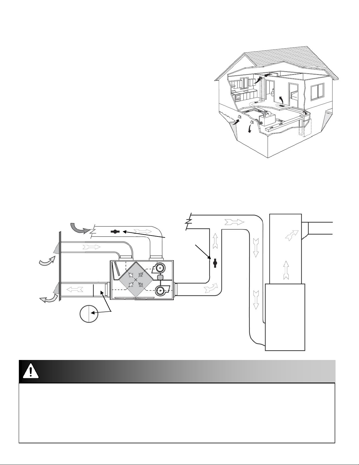
Simplified Installation (Return/Return Method) ................................................................................ 4
Partially Dedicated System ............................................................................................................ 5
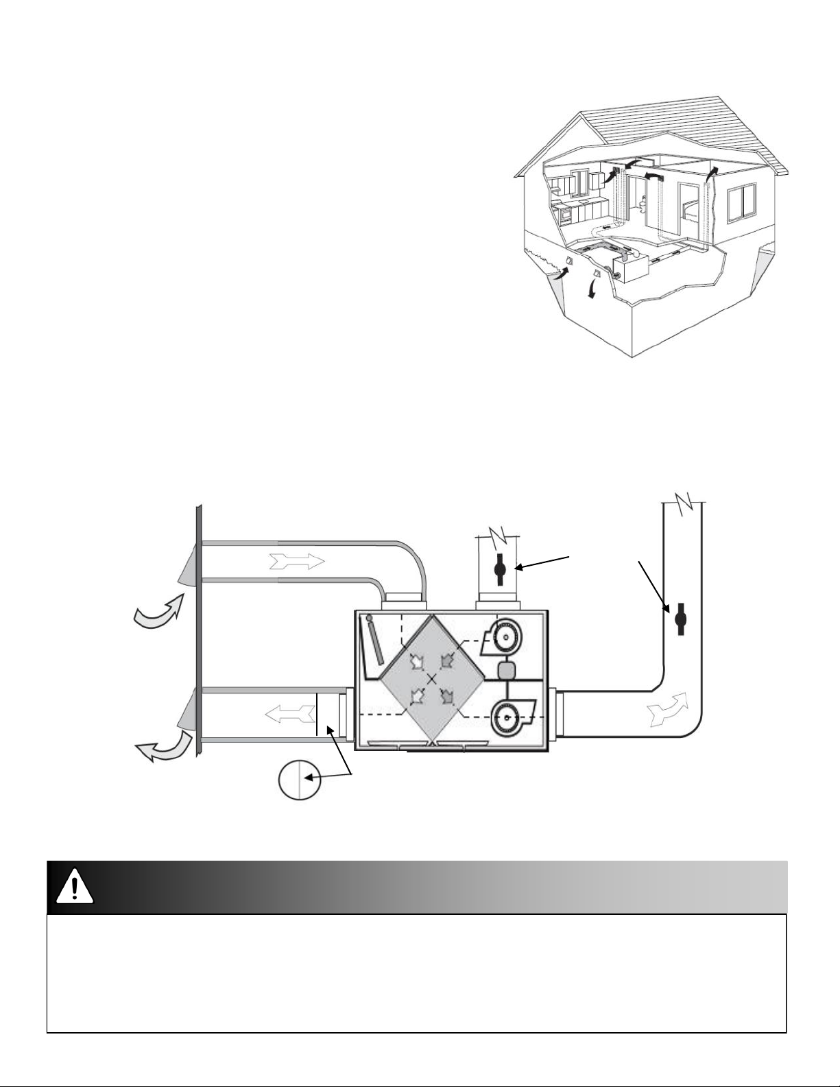
Fully Dedicated System ................................................................................................................. 6
Hanging Straps ............................................................................................................................ 7
Drain Connection ......................................................................................................................... 8
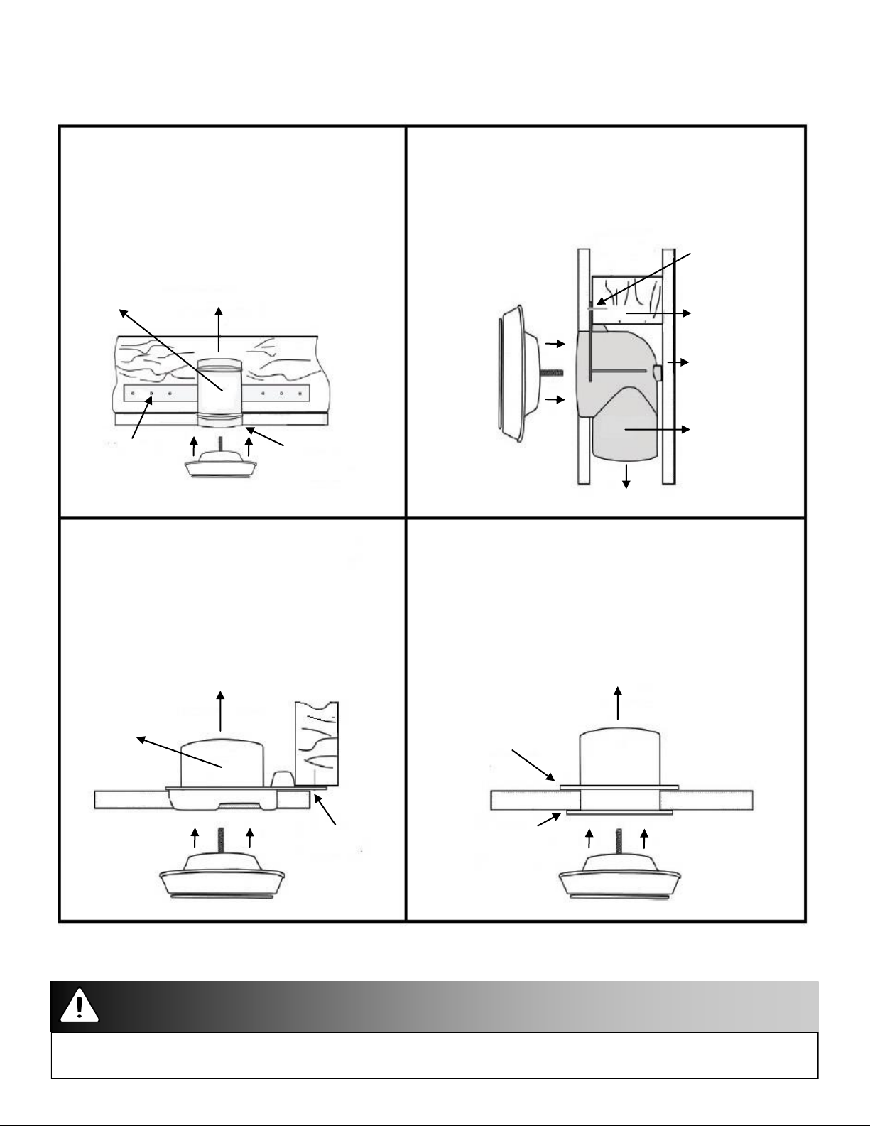
Grilles ......................................................................................................................................... 9
Grille Fittings .............................................................................................................................. 10
Airflow Weatherhood and Weatherhood Requirements ................................................................... 11
Dual Hood .................................................................................................................................. 12
Main Control Installation .............................................................................................................. 13
Mechanical Timers Installation ...................................................................................................... 14
Installation and Operation 20/40/60 Minute Timers: 99-DET01 ........................................................ 17
Installer Selectable High Speed Settings ....................................................................................... 16
Dimensional Model Drawings - AIR135-ES Model ............................................................................ 17
Balancing the Airflows ................................................................................................................. 18
Determining the CFM ................................................................................................................... 19
Balancing Collar Instructions ........................................................................................................ 19
Balancing the Airflows with a Pitot Tube ....................................................................................... 20
Balancing the Airflow Using the Door Ports ................................................................................... 21
Airflow Reference Chart - AIR135-ES ............................................................................................. 22
Troubleshooting .......................................................................................................................... 24
Installation and Operation of Wireless 20/40/60 Minute Timers: 99-DET02....................... ................. 15
Installation and Pairing of Repeaters: 99-RX02.............................................................. .................. 16

Pre-Installation Notes
Read this notice before installing unit:
Disconnect the power from the unit before cleaning or servicing
To prevent electrical shock, it is extremely important to confirm the polarity of the power line that is switched by the
safety (disconnect) switch. The hot line (black) is the proper line for switching. Use either a voltmeter or test lamp
to confirm the absence of a voltage between the disconnect switch and ground (on the cabinet) while the door is
open. This procedure must be followed, as dwellings are occasionally wired improperly. Always ensure the proper
grounding of the unit.
Improper installation, adjustment, alteration, service or maintenance can cause property damage, personal injury or
loss of life. Installation and service must be performed by a qualified installer or service agency.
Warning
Do not apply electrical power to the unit until after the completion of the installation (including installation of low
voltage control wiring).
Ensure the installation and wiring is in accordance with CEC, NEC, and local electrical codes.
Plug the unit into a standard designated (120 VAC) electrical outlet with ground.
The use of an extension cord with this unit is not recommended. If the installation requires further wiring, have a
licensed electrician make all of the electrical connections. The recommended circuit is a separate 15 A/120 V circuit.
Attention
Before installation, careful consideration must be given to how this system will operate if connected to any other
piece of mechanical equipment, i.e. a forced air furnace or air handler, operating at a higher static. After
installation, the compatibility of the two pieces of equipment must be confirmed, by measuring the airflows of the
HRV, by using the balancing procedure found in this manual. Never install a ventilator in a situation where its
normal operation, lack of operation or partial failure may result in the backdrafting or improper functioning of
vented combustion equipment.
Unit must be installed level to ensure proper condensate drainage. Due to the broad range of installation and
operational conditions, consider the possibility of condensation forming on either the unit or connecting ducting.
Objects below the installation may be exposed to condensate.
Do not install control wiring alongside electrical wire.
Caution
Due to ongoing research and product development, specifications, ratings, and dimensions are subject to change
without notice.
Note
3

Simplified Installation (Return/Return Method)
Installation Notes
The HRV must be balanced.
Unit should be balanced on high speed with the furnace
blower on.
It is mandatory that the furnace blower run continuously
or HRV operation be interlocked with the furnace blower.
The duct configuration may change depending on the
HRV model.
A backdraft damper is recommended in the exhaust air
duct to prevent outdoor air from entering the unit.
The airflow must be confirmed on site using the
balancing procedures found in this guide.
Spring-Loaded Backdraft Damper (Recommended)
Install the backdraft damper with the leaf hinge vertical. The damper is installed on the “Stale Air to
Outside Collar”
3’ min.
recommended
Forced Air
Furnace
Cool Air
Return
Dampers for
balancing
airflows
Outdoors
Return Air
Backdraft Damper
Leaf Hinge
Installed Vertically
(Recommended)
Check local codes/authority having jurisdiction for acceptance.
Applications such as greenhouses, atriums, swimming pools, saunas, etc. have unique ventilation requirements
which should be addressed with an isolated ventilation system.
Weatherhood arrangement is for drawing purposes only. Check local codes/authority having jurisdiction for
acceptance.
Back draft dampers are recommended for the stale air to outside air duct. This damper prevents outdoor air from
entering the HRV during the operation of the furnace/air handler while the HRV is in standby, off, or recirculating.
Attention/Warning
4

Partially Dedicated System
Installation Notes
The HRV must be balanced.
Unit should be balanced on high speed with the furnace
blower on.
It is recommended that the furnace blower run
continuously or HRV operation be interlocked with the
furnace blower. Refer to building code.
The duct configuration may change depending on the
HRV model.
A backdraft damper is recommended in the exhaust air
duct to prevent outdoor air from entering the unit.
The airflow must be confirmed on site using the
balancing procedures found in this guide.
Spring-Loaded Backdraft Damper (Recommended)
Install the Backdraft Damper with the leaf hinge vertical. The damper is installed on the “Stale Air to
Outside Collar”
Forced Air
Furnace
Cool Air
Return
Dampers for
balancing
airflows
Outdoors
Backdraft Damper
Leaf Hinge
Installed Vertically
(Recommended)
EXHAUST AIR from various parts of home. i.e.
bathrooms (if required), kitchens (if required)
RETURN AIR
5
Check local codes/authority having jurisdiction for acceptance.
Applications such as greenhouses, atriums, swimming pools, saunas, etc. have unique ventilation requirements
which should be addressed with an isolated ventilation system.
Weatherhood arrangement is for drawing purposes only. Check local codes/authority having jurisdiction for
acceptance.
Back draft dampers are recommended for the stale air to outside air duct. This damper prevents outdoor air from
entering the HRV during the operation of the furnace/air handler while the HRV is in standby, off, or recirculating.
Attention/Warning

Fully Dedicated System
Installation Notes
The HRV must be balanced.
When balancing, all external exhaust systems should be
turned off (i.e. range hood, dryer exhaust, bathroom
vents).
All exhausting appliances should have their own make-up
air, as this is not an intended use of the HRV system.
The duct configuration may change depending on the
HRV model.
The airflow must be confirmed on site using the balancing
procedures found in this guide.
Spring-Loaded Backdraft Damper (Recommended)
There is a location for an optional Backdraft Damper with the leaf hinge vertical. The damper is
installed on the “Stale Air to Outside Collar”
Outdoors
Dampers
for
balancing
airflows
Stale air from various
parts of home i.e.
bathrooms (if required)
kitchens (if required)
Fresh air to house:
main living areas,
bedrooms, living
room, rec. room etc.
Location for optional
Backdraft Damper
Leaf Hinge
Installed Vertically
6
Check local codes/authority having jurisdiction for acceptance.
Applications such as greenhouses, atriums, swimming pools, saunas, etc. have unique ventilation requirements
which should be addressed with an isolated ventilation system.
Weatherhood arrangement is for drawing purposes only. Check local codes/authority having jurisdiction for
acceptance.
Back draft dampers are recommended for the stale air to outside air duct.
Attention/Warning

7
Hanging Straps - Installation Notes
Use 4 screws and 4 washers (not provided) to attach the hanging straps to the floor joists. The
washer must be wider than the eyelet of the grommet on the hanging strap. The hanging straps
are designed to reduce the possibility of noise, resonance and harmonics.
Must push up on the bottom of the HRV when pulling the hanging straps.
Attention
Step 3: Hook the bottom grommets of the
straps through the “S” hooks. Pull down
vertically on the handle loops while lifting
the bottom of the unit.
Step 1: Insert the screws and washers
(not included) through the hanging strap
grommets and fasten to the joists.
Figure A
Step 4: Level the unit from right to left to right
and front to back. Adjust the unit up by pulling
down vertically on the hand loops while lifting up
on the bottom of the cabinet.
Step 5: Fold the hand loops in excess strap
and secure with a nylon tie (not included).
Figure B
Screws (not included)
Hand Loops
Hanging Strap Grommets
Washers (not included)Buckles
Hand Loops
Note: Pull down on the
hand loops while lifting
Screws
“S” Hooks
Note: This illustration of
the unit may vary from the
diagram shown.
Joist
Buckles
Figure C
Step 2: Unscrew the 4 machine screws located
on the upper side of the unit. Attach the “S”
hooks and reinsert the machine screws.
7

8
The HRV and all condensate lines must be installed in a space where the temperature is maintained above the
freezing point or freeze protection must be provided.
Drain trap and tubing must be below bottom of door with 1/4 in per foot downwards slope away from unit.
A secondary drain pan may be required to protect from condensate leakage.
Drain Connection
Installation Notes
The HRV cabinet has pre-punched holes for the drain (see below).
The HRV may produce some condensation during a defrost cycle. This water should flow into a nearby
drain, or be taken away by a condensate pump.
1.
Pour a cup of water into the drain pan of the HRV after the drain connection is complete. This
creates a water seal which will prevent odours from being drawn up the hose and into the fresh air
supply of the HRV.
Caution
Hard Pipe Plumbing
To Drain
Pre-Punched Holes (2)
Drain Pan Drain Pan
1/2 in Hard Pipe Tee
Joint
Drain
Spout
Drain Hose Plumbing
Drain Spout
1/2 in I.D.
Drain Hose
Tee Connector
To Drain
Zip Tie
Drain
Spout
Drain Pan Drain Pan
Pre-Punched Holes (2)
7.
The HRV cabinet has pre-punched holes for the drain (see below).
Insert the drain spout through the hole in the drain pan.
2. Tighten the nut which holds the drain spout in place.
3. Construct a P-trap using the plastic tee connector. (see below)
4. Cut two lengths of 1/2 in drain hose (not included) and connect the other ends to the two drain spouts.
5. Position the tee connector to point upward and connect the drain line.
6. Tape or fasten base to avoid any kinks.

Adjustable grilles should be used to balance the flow rates into and out of various rooms. The
grilles should not be adjusted after balancing the unit.
Grilles or diffusers should be positioned high on the wall or in the ceiling. Kitchen exhaust should
never be connected to the range hood. They should be installed at least 4 ft (1.2 m) horizontally
away from the stove.
Field supplied balancing dampers should be installed external to the unit to balance the amount
of stale air being exhausted with the amount of fresh air being brought into the house. Refer to
airflow balancing section.
The Airflow Kitchen Grille
(part# 99-10-002 6 in x 10 in)
The Airflow Kitchen Grille includes a
removable grease filter. Most building codes
require that kitchen grilles are equipped
with washable filters.
The Airflow TechGrille
The TechGrille is a round, fully adjustable grille,
which provides quiet air distribution.
Grilles
4 in (100 mm) Part # 99-EAG4
5 in (125 mm) Part # 99-EAG5
6 in (150 mm) Part # 99-EAG6
8 in (200 mm) Part # 99-EAG8
Removable Filter
Airflow
Supply
Airflow
Exhaust
9

Do not mount exhaust grille within 4 ft (1.2 m) (horizontally) of a stove to prevent grease from entering the unit.
Caution
Grille Fittings
Rough-in Metal Fitting
(part # 99-RIMF 4/5/6/8)
Use this rough-in fitting before the drywall is
installed.
Nail or screw the fitting onto the floor post.
Available sizes are 4 in, 5 in, 6 in, and 8 in.
Connect to HRV ducting
Floor joist
Ceiling
Flush mount the
rim with the
finished ceiling
TechGrille
Nail or screw
strap fitting
onto floor
Rough-in
Metal
Fitting
Stack Head Elbow (part # 99-WF4 / 99WF6)
Use this rough-in fitting before the drywall is installed. This
fitting is ideal for running ducting through 2 x 4 (min.)
studded walls.
Nail to stud.
Available sizes are 4 in and 6 in.
Nail stack head
elbow onto stud
2 x 4 Stud
1/2 in drywall
Stack Head
Elbow
Connect to HRV ducting
TechGrille
Quick Mount Fitting
(part # 99-QM 4/5/6)
Use this rough-in fitting before the drywall is
Installed.
Nail fitting onto the stud.
Available sizes are 4 in, 5 in, and 6 in.
Connect to HRV ducting
2 x 4 Stud
Nail or screw quick
mount fitting to stud
TechGrille
1/2 in drywall
Quick Mount
Fitting
Ceiling/Wall Fitting (part # 99-CF 4/5/6/8)
Use this fitting for ceiling tiles or finished/installed drywall.
Cut a hole through the ceiling tile, insert the fitting and use the
retaining ring to hold the fitting in place.
For finished/installed drywall, use caulking around the lip if you do
not have access to attach the retaining ring.
Available sizes are 4 in, 5 in, 6 in, and 8 in.
Connect to HRV ducting
Wall/Ceiling
Fitting
Retaining ring
Flush mount the lip of the
ceiling/wall fitting to ceiling
and drywall fitting TechGrille
Ceiling
10

11
Airflow Weatherhood
Fixed covered weatherhoods have a built-in bird screen with a 1/4 in (6 mm) mesh to prevent foreign
objects from entering the ductwork.
Installation Notes
The inner and outer liners of the flexible insulated duct must be clamped to the sleeve of the
weatherhoods (as close to the outside as possible) and the appropriate port on the HRV. It is very
important that the fresh air intake line be given special attention to make sure it is well sealed. A good
bead of high quality caulking (preferably acoustical sealant) will seal the inner flexible duct to both the
HRV port and the weatherhood prior to clamping.
The flexible insulated duct that connects the two outside weatherhoods to the HRV should be stretched
tightly and be as short as possible to minimize air flow restrictions.
Twisting or folding the duct will severely restrict airflow.
Hard (rigid) ducting which has been sealed and insulated should be used for runs over 10 ft
(3.3 m). Refer to your local building code.
Screen
(side view)
1/4 in (6 mm)
Screen
Exterior wall
Collar is supplied to
ensure vapor barrier is
100% sealed to wall plate
12 i
n galvanized
pipe supplied
Weatherhood Requirements
Check local codes/authority having jurisdiction for acceptance and spacing
requirements for weatherhoods.
Do not locate in garage, attic or crawl space.
Intake:
Should be located upstream (if there are prevailing winds) from the exhaust outlet.
Not near dryer vents, furnace exhaust, driveways, oil fill pipes, gas meters, or garbage
containers.
Exhaust:
Not near a gas meter, electric meter or a walkway where fog or ice could create a hazard.
Contact your local building authority before installation of the Dual Hood to verify compliance with
local building codes.
Attention

12
Contact your local building authority before installation of the Dual Hood to verify compliance with
local building codes.
Caution:
Sealant must be applied as per instructions or leakage and condensation may occur.
Insulate the Fresh Air Supply and Stale Air Exhaust duct work back to the unit.
Attention/Caution
Dual Hood Part 99-190
With the Airflow Dual Hood, only one 6 in hole is required in the exterior wall to complete two
connections: fresh air intake and stale air exhaust.
13"
Top View
8.25" 6"
8.25"
25"
Side View
6" 5" 6"
21.5"
Stale Air
Exhaust
Fresh Air
Intake
SideView of Hood and Backplate
Tested by: National Research Council Canada
Program: Building Regulations for Market Access Report Number: A1-007793
Report Date: 15 February 2016
Found to comply with requirement as set in the NBC
Note

13
Main Control Installation
The Airflow Digital Control 99-GDXPL02 is to be surface mounted onto a wall and the Airflow
Ventilation Controls 99-GBC02, 99-GBC03 and 99-GBC04 may either be installed onto a flush
mounted electrical switch box or surface mounted onto a wall. Only one master control should be installed
to a ventilation system (the face plate on this illustration may not be exactly the same as yours).
Operating
Instruction
Card
1 in hole for Wiring
wire opening. Terminals
Keep top / bottom
vent openings clearFigure
D
Face
Plate
Back
Plate
Pay special attention not to damage the contact pins when removing and detaching the face plate (Figures B and C).
Attention
Figure
E
1.625"
0.75"
1.625"
1/8 in hole for
screw and
anchor
1 in x 3/4 in
for wire
opening
Wiring
Terminals
1/8 in hole
for screw and
anchor
oval hole
Break off tab
Alternate Wall Mount
1/8 in hole for
screw and
anchor
1 in x 3/4 in 0.75"
oval hole
1/8 in
for wire
hole for
opening
screw and
anchor
Wiring
Terminals
Break off tab
Figure
F
1"
Wire hole
centered
between
screw
holes
1"
(Two) 1/8 in hole for
screws and anchors.
Back PlateFigure C
Face Plate
Figure A Figure B
Keep top / bottom
vent openings clear
1. For GDXPL02 Control, remove the operating
instructions and card from the top of the control
(Figure A).
2. Separate the face plate from the back plate by
firmly pulling apart (Figures B or C). Be careful
not to damage face plate contact pins.
3. For GDXPL02 control, place the back plate of the
control in the desired location on the wall and
pencil mark the wall with the right and left screw
holes (Figure D).
4. For GBC02, GBC03 or GBC04 controls, place the
back plate of the control in the desired location
on the wall and pencil mark the top and bottom
screw holes (Figure E or F). For mounting the
control without a Decora plate, break off top and
bottom tabs and refer to Figure F for mounting.
5. Remove the back plate from the wall and mark
the center hole for the wires in the middle of the
screw holes. Refer to Figure D, E or F for
dimensions.
6. Drill (two) 1/8 in holes for the screws and wall
anchors (Figure E, E or F). For GDX control, drill
a 1 in hole in the center (Figure D). For GBC
controls, cut in a 3/4 in by 1 in oval hole in the
wall (Figure E or F).
7. Pull 3 wire 20 gauge (min.) 100 ft length (max.),
through the opening in the wall.
8. Connect red, green and yellow to the wiring
terminals located on the back plate (Figure D, E
or F).
9. Attach the back plate to the wall using two
supplied screws and anchors.
10. Attached the face plate to the back plate
(Figure B or C). Note: Be careful to correctly align
the face plate to avoid damaging the face plate
contact pins.
11. For GDXPL02 control, insert the operating
instructions card into the control (Figure A).
12. Connect the 3 wire 20 gauge (min.) 100 ft length (max.) to the terminal block located on ventilator (Red #3,
Yellow #4 and Green #5).

14
Mechanical Timers Installation 99-101
The Mechanical Timer is a 2 wire “dry
contact” timer. A jumper wire must be
connected between 2 (ON) and 3 (RED).
Connect the 2 timer wires to ON and HI.
2 wire timers require a
jumper wire between
ON and RED on the
terminal block Connect the 2
wires from the
timer to ON and HI on the terminal block.
HRV Terminal Block
Wire
Connector
Furnace
Terminal Strip
Furnace
Thermostat
Interlocking the HRV to an Air Handler or Furnace
Blower
Connecting the HRV as illustrated will ensure the air handler/
furnace blower motor is operating whenever
the HRV is venting.
The HRV must be interlocked to the furnace/air handler with a
simplified installation (return/return installation) and should be
interlocked with a partially dedicated installation.
Setting “Standby” When Using a Main Control
The HRV will be “fully-off” when the off position is selected on the
Timers mount in standard electrical boxes
Use 3 wire 20 gauge (min.) 100 ft length (max.) low voltage wire and multiple timers individually wired back to the unit.
Caution:
Consideration should be given to competing airflows when connecting the HRV in conjunction with an air handler/furnace
blower system.
Building codes in some areas require “fully-off” functionality. Check with your local building authority before modifying the
unit to
“standby-off”. Unintentional operation of the HRV by the end user may occur if the unit is modified from “fully-off” to
“standby-off”.
Attention/Caution
Main Control. Timers and/or other controls will not function when the HRV is in the off position.
The “fully-off” feature can be modified to “standby-off” by adding a jumper on the terminal block between 2
(ON) and 3 (RED). “Standby” can also be achieved by setting the main control to the ON position and selecting
speed 0*. Timers and/or additional controls will initiate high speed ventilation when activated.
*Speed 0 is not available on all controls.
Operating the HRV With Dry Contact Controls
A jumper must be in place between 2 (ON) and 3 (RED) on the terminal block to activate the HRV for timers and/
or dry contact controls.
Adding Dry Contact Controls
Low Speed: A jumper between 2 (ON) and 1 (LOW) initiates low speed ventilation.
High Speed: A jumper between 2 (ON) and 6 (HI) initiates high speed ventilation.
Dehumidistat: A dry contact for a Dehumidistat is connected between 2 (ON) and 10 (BLK)

Installation and Operation of Wireless 20/40/60 Minute Timer: 99-DET02
15
GBC02, GBC03
or GBC04
Control
NOTE: Your
control may look
different than the
one shown.
Press Simultaneously
to Initiate Pairing Mode
Figure A
Figure
D
NOTE
Thewireless Timers and Repeaters must be matched to
the main wall control of the HRV / ERV. This process is
called "Pairing". Multiple Timers and Repeaters can be
paired to a single wall control.
Figure
B
1/8 in hole for
screw and
anchor
1/8 in hole
for screw and
anchor
Break off tab
Alternate Wall Mount
1/8 in hole for
screw and anchor
Figure
C
Back Plate
Face Plate
1/8 in
hole for
screw and
anchor
Break off tab
Figure
F
Figure
E
Press Simultaneously
to Initiate Pairing
Mode
GDXPL02
Control
DET02 Timer
20/40/60 Minute
Status Lights
Select Button initiates
high speed ventilation
for 20, 40 or 60 min.
Battery Indicator
Removable
Backplate
The Timers may be installed onto a flush mounted electrical
switch box or it may be surface mounted onto a wall. Multiple
Timers may be installed in a ventilation system. To increase
the range of a wireless Timer, a RX02 Repeater should be used.
Pairing:
mode when Timers have been successfully paired.
To pair additional DET02 Timers with the same wall control, or
if pairing was not successful, repeat steps 1-6.
When paired, the DET02 Timers can be moved and installed
elsewhere. Estimated range of the Timer is 40’ with no
obstructions. A RX02 Repeater may be installed to increase the
range of the Timers.
Test if pairing was successful by pressing the Select Button and
listen for the HRV / ERV to initiate HIGH fan speed Ventilation.
Un-pairing:
1. Turn on the main wall control by pressing the ON/OFF
button and remove the battery from Timer.
2.
DET02 with GDXPL02 Controls:
Press the left and
right buttons simultaneously on the main wall control
( and RESET buttons). The screen will go blank and the
wireless symbol will appear flashing on the bottom right
of the display. This indicates that the main control is now in
pairing mode. (Figure D)
3.
DET02 with GBC02, GBC03 or GBC04
Controls:
Press the left and right buttons simultaneously on the main
wall control ( and either or buttons, depending on
the main control). The bottom row of 3 LED's will begin
flashing. This indicates that the main control is now in
pairing mode.(Figure E)
4. Keep the Timer within 16” of the main wall control when
pairing.
5. Install the battery in the DET02 Timer. All four lights on
the Timer will immediately flash 5 times, then only the red
battery light will remain on for approximately 12 seconds
after which the "40" light flashes the rev code. 20, 40, 60
lights will flash until paired or will stop if not paired within
12 seconds. If pairing was not successful you now must
return to step 1 to restart the pairing process.
6. Press the button on the main wall control to exit pairing
1. Remove the battery from the back of the DET02 Timer
2. Press and hold the Select Button on the front of the Timer
3. While holding the Select Button, reinsert the battery in the
Timer. Continue holding the select button until the LED
under "40" begins flashing. The DET02 Timer will now be
unpaired with the main wall control.
Installation:
1. Separate the face plate from the back plate by firmly
pulling apart (Figure A).
2. For mounting the control without a Decora plate, break off top and bottom tabs and refer to Figure C for mounting.
3.Place the back plate of the control in the desired location on the wall and pencil mark the top and bottom screw holes
(Figure B or C). Drill two 1/8" holes.
4. Attach the back plate to the wall using the 2 supplied screws and anchors.
5. Attach the face plate to the back plate (Figure A).

16
The circuit board on this unit has adjustable DIP switches for the selection of speeds
Hi1, Hi2 or Hi3. The factory setting is Hi3. Refer to the specification page found online at;
www.Airflow.com for the airflow rates on Hi1, Hi2 and Hi3. Note: Low speed is not adjustable.
DIP 1 ON R2000 defrost cycle disabled (factory setting)
DIP 1 OFF R2000 defrost cycle enabled
DIP 2 ON recirculate defrost models
DIP 2 OFF damper defrost and fan defrost models
Illustration of DIP switches 3
and 4 in the ON position
(factory setting).
Functionality of DIP
Switches 1 and 2
Description Switch 1 Switch 2 Switch 3 Switch 4
Hi 3 (factory default) Factory Setting “ON” Leave on factory setting ON ON
Hi 2 Factory Setting “ON” Leave on factory setting OFF ON
Hi 1 Factory Setting “ON” Leave on factory setting ON OFF
Installation and Pairing of Repeaters: 99-RX02
The RX02 Repeaters are to be plugged directly into a 120V power outlet
1. Turn on the main wall control by pressing the ON/OFF button .
2.
RX02 with GDXPL02 Controls:
Press the left and right buttons simultaneously on the main wall
control ( and RESET buttons). The screen will go blank and the wireless symbol will appear
flashing on the bottom right of the display. This indicates that the main control is now in pairing
mode.
RX02 with GBC02, GBC03 or GBC04 Controls:
Press the left and right buttons
simultaneously on the main wall control ( and either or buttons, depending on the main
control). The bottom row of 3 LED's will begin flashing. This indicates that the main control is now
in pairing mode.
3. The RX02 Repeater must be powered within 16” of the main wall control for pairing. If an outlet is
not available an extension cord should be used to power the repeater initially for pairing.
4. Plug the RX02 Repeater into the power outlet. The green light will flash after approximately 12
seconds indicating that the repeater is paired with the main wall control.
5. Press the ON/OFF button on the main wall control to exit pairing mode and the Repeater may
RX02
Repeater
Power
Plug
now be unplugged and moved to its permanent location.
To pair additional RX02 Repeaters with the same wall control, repeat steps 1-5 until
all Repeaters have been paired.
When installed in its permanent location, the green LED will remain solid to indicate
the best location and the Repeater can be moved farther if required. The green LED
will flash to indicate it is in a good location. A red light indicates the Repeater is out
of range and needs to be moved closer to the main wall control.
Installer Selectable High Speed Settings

17
17 1/4 in (438 mm)
22 3/4 in (578 mm)
14 in (356 mm)
Front View Top View
Fresh
Air From
Outside
Stale
Air To
Outside
Fresh
Air To
Inside
Stale
Air From
Inside
Condensate Drains
Motorized
Impeller
Removable
Heat Recovery
Core
Recirculating
Defrost Damper
(For TPD
Model Only)
Filter
Note: Front clearance of 25 in (635 mm) is
recommended for servicing unit. All ducts
use 5 in (125 mm) oval collars, balancing
dampers are located on all collars.
Installation and Operation 20/40/60 Minute Timer: 99-DET01
Status
Lights
Select Button
initiates high
speed ventilation
for 20, 40 0r 60
min.
Yellow
Red
Green
Installation
The 99-DET01 Timers are to be surface mounted onto a wall. Multiple Timers may be
installed in a system. Once mounted, connect Yellow, Red, Green wires on side of 99-
DET01 to the terminal block on unit using 3 wire 20 gauge (min.) 100 ft length (max.).
Operating your Lifestyle 20/40/60 Minute Fan Timer
Press and release the Select Button to activate a 20, 40 or 60 minute HIGH speed
override cycle. The Light will illuminate and the unit will run on HIGH speed
Ventilation for the selected time. The Light will dim after 10 sec. for run time. The
Light will flash during the last 5 min. of the cycle. All Timers connected to the unit
will illuminate for the duration of the override when the Select Button is pressed.
Lockout Mode
Lockout Mode is useful if you wish to disable the Timers.
The timer can be set to lockout mode by pressing and holding the Select Button for five seconds. After 5 sec., the Light will
flash; release the Select Button. The Timer is now in lockout mode. If the Select Button is pressed during lockout mode the
Light will momentarily illuminate but no override will be initiated.
If lockout mode is initiated when the timer is activated, the timer will continue its timed sequence but will not allow any
further overrides to be initiated. Lockout mode can be unlocked by pressing and holding the Select Button for 5 sec. After 5
sec. the Light will stop flashing. Release the Select Button and the timer will now operate normally.
Dim
ensional Drawing for AIR135-ES Model

18
Continuous, excessive, positive pressure may drive moist indoor air into the external walls of the building. Once
inside the external walls, moist air may condense (in cold weather) and degrade structural components or cause
locks to freeze.
Continuous, excessive, negative pressure may have several undesirable effects. In some geographic locations, soil
gases such as methane and radon gas may be drawn into the home through basement or ground contact areas,
and may also cause the backdrafting of vented combustion equipment.
Attention
Balancing the Airflows
Balan
cing the airflows is critical to ensuring that the amount of air introduced from the outside of
the building equals the amount of air exhausted to the outside of the building. If these two airflows
are not properly balanced, the following issues may occur:
A positive or negative pressure in the house
HRV not operate at its maximum efficiency
The unit not defrost properly
Airflow Measuring Gauge
A digital manometer is a suitable instrument for the balancing of
airflows.
99-BAL-KIT AirflowBalancing Kit
Kit includes a digital manometer, pitot tube, hose and tool bag. Figure A
Digital Manometer
Gauge Attachments
When sampling an airflow, various attachments are available
for use on a digital manometer. Consult with your Airflow
distributor for available options such as a pitot tube, flow
measuring station, and an airflow measuring probe.
Figure B illustrates a digital manometer with a pitot tube
attachment. This combination will measure the system air
velocity pressure accurately, regardless of the duct size or
shape (either round or rectangular). Figure B
Digital manometer with a
pitot tube attachment
DUCT
AIR
FLOW
Pitot tube
Digital
manometer

19
Units with Balancing Collars
Install these units with the dampers fully open and damper down the duct with the higher airflow
to equal the lower airflow. Refer to the “Balancing the Airflows” page found in this manual.
All other units require dampers for balancing airflows installed into the “Fresh Air to Building” and
“Stale Air from Building” ductwork.
When connecting ductwork to
the collar, take note where
screws are located. Screws
should be located no further
than 1/2 in from outside edge of
collar, so as not to impede
operation of the damper.
1/2 in
Push and turn with slotted
screwdriver. Damper
automatically locks when
pressure is released.
Hard/Rigid Ducting Insulated flexible ducting
Installations where the HRV is ducted directly to the return of a furnace may require additional dampening on the
fresh air to building duct. This is due to the high return static pressures found in some furnace installations.
Attention
Determining the CFM
After balancing the airflows, calculate the CFM flow rate.
Example
This example shows how to determine the airflow for a 6 in
diameter duct. If the duct velocity pressure reads 0.025 in w.g.
on the digital manometer, use the chart that came with the pitot
tube to determine a duct velocity of 640 ft/min. for a duct velocity
pressure of 0.025 in w.g.
CFM Calculation
CFM = feet per minute x cross section area of duct
= 640 x 0.196
= 125
Cross section area of some common duct
sizes:
0.087 for 4 in duct
0.196 for 6 in duct
0.139 for 5 in duct
0.267 for 7 in duct

20
Balancing Preparation
Prior to performing the air balancing procedure, perform the following steps:
Seal the ductwork.
Confirm the installation and proper operation of all the components of the HRV.
Fully open the balancing dampers.
Turn off all household exhaust devices (range hood, clothes dryer, bathroom fans).
Set the HRV at high speed.
Prior to balancing the unit, first adjust airflows in the branch lines to specific areas of the house.
If the outdoor temperature is below 0oC (32oF), ensure the unit is not running in defrost.
If the system is a simplified or partially dedicated installation, operate the furnace/air handler at
high speed.
Balancing the Airflow With a Pitot Tube
Step 2: Insert the pitot tube with the tip facing towards the air
stream in the stale air from Building air stream. Move the pitot
tube around in the duct (facing toward the airflow) and take an
average reading. Record the reading.
Step 3: Repeat step 2
to measure the fresh air to building duct.
Pitot tube tip facing
towards the air stream.
Balancing
Damper
Drill 3/16 in holes in
Stale & Fresh air
ducts.
Fresh Air to Building
Balancing Damper
Step 1: Drill a 3/16 in hole in the duct, ideally 3
ft downstream and 1 ft upstream of any elbows
or bends in the fresh air and stale air streams.
Stale Air from Building
Pitot tube tip facing
towards the air stream
Balancing Damper
Step 4(a): Review the readings and damper down the duct with
the highest duct velocity pressure. Repeat step 2 and step 3 until
both ducts show identical readings.
Step 4(b): Upon completion of balancing, seal the holes (foil tape
recommended).
Seal holes.
Balancing
Damper
Table of contents
Other Airia Fan manuals