AirMaid AirMaid V Installation and maintenance instructions

Installation and service guide for
AirMaid® V ozone cleaning system
20 000 V
Ai r MA i d ® o z o n e c l e A n i n g s y s t e M
i n n o v A t i v e A i r t r e A t M e n t

1. Check Product
2. System Overview
3. Installation Guidelines
4. Electrical connection and settings
5. System Test
6. Service and Maintenance
7. Technical Specication
8. Airmaid® Product Registration
Check that the shipment consists of the components below and that there is no visible damage. Any discrepancy must
always be reported immediately to the distributor or manufacturer. Read through the complete guide before starting
the installation.
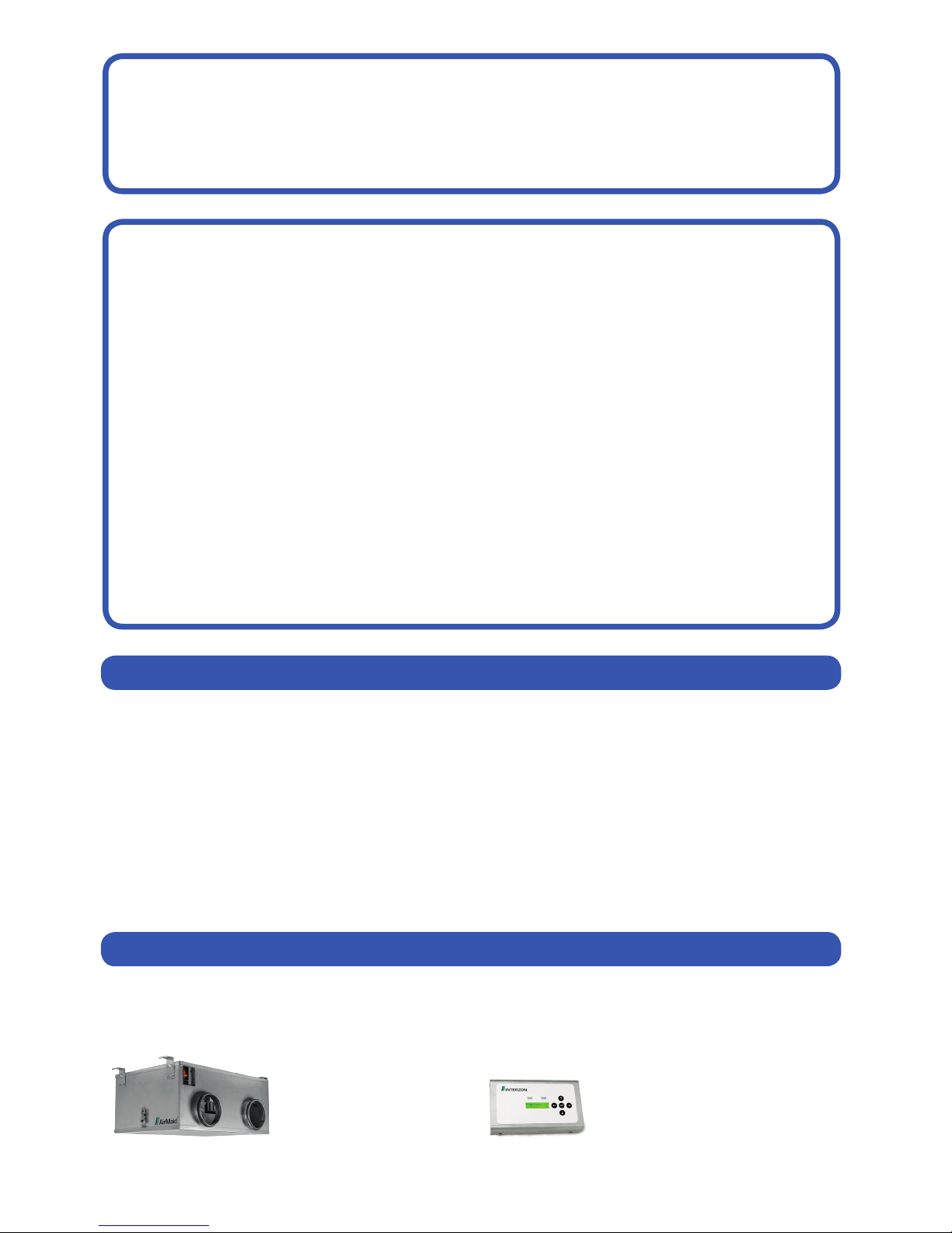
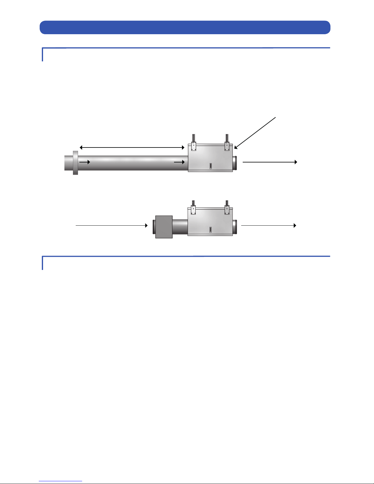
1 x AirMaid® Ozone Generator 1 x AirMaid® Alarm Panel
CONTENT
1 CHECK PRODUCT
LIMITED WARRANTY FOR INTERZON EQUIPMENT
This warranty is subject to the following conditions.
A new product is warranted to be free from defects and workmanship for a period of 2 years. If the product regis-
tration form is submitted to Interzon within ten (10 days) from the completion of the installation, the guarantee
will commence on this date.
A spare part is warranted to be free from defects and/or workmanship for a period of ninety (90) days from the
date of the original installation.
The warranty for new equipment covers the repair or replacement of the defective part and includes labor
charges according the recommended hours by Interzon and maximum kilometer charges of 300 km round trip.
The warranty for spare parts covers only the repair or replacement of the defective part and does not include any
labor charges for the removal and installation of any parts, travel or other expenses incidental to the repair or
replacement of a part.
Any claim must be presented to either Interzon or the distributor from whom the product was purchased. No
allowance will be granted for repairs made by anyone else without Interzon written consent. If damage occurs
during shipping, notify the sender at once so that a claim can be led.
The above limited warranty does not apply to damage resulting from accident, alteration, misuse or if the serial
number is removed or defaced.
2
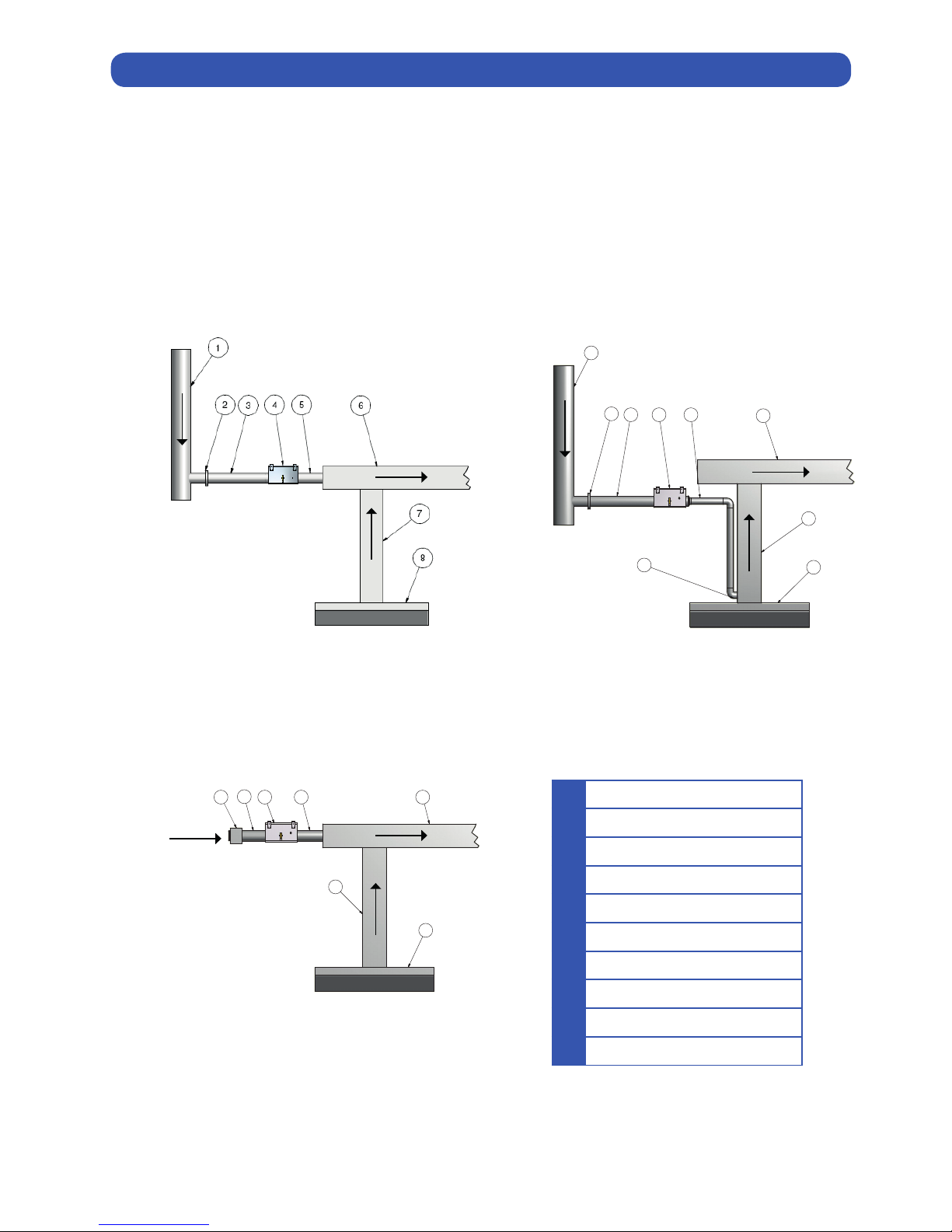
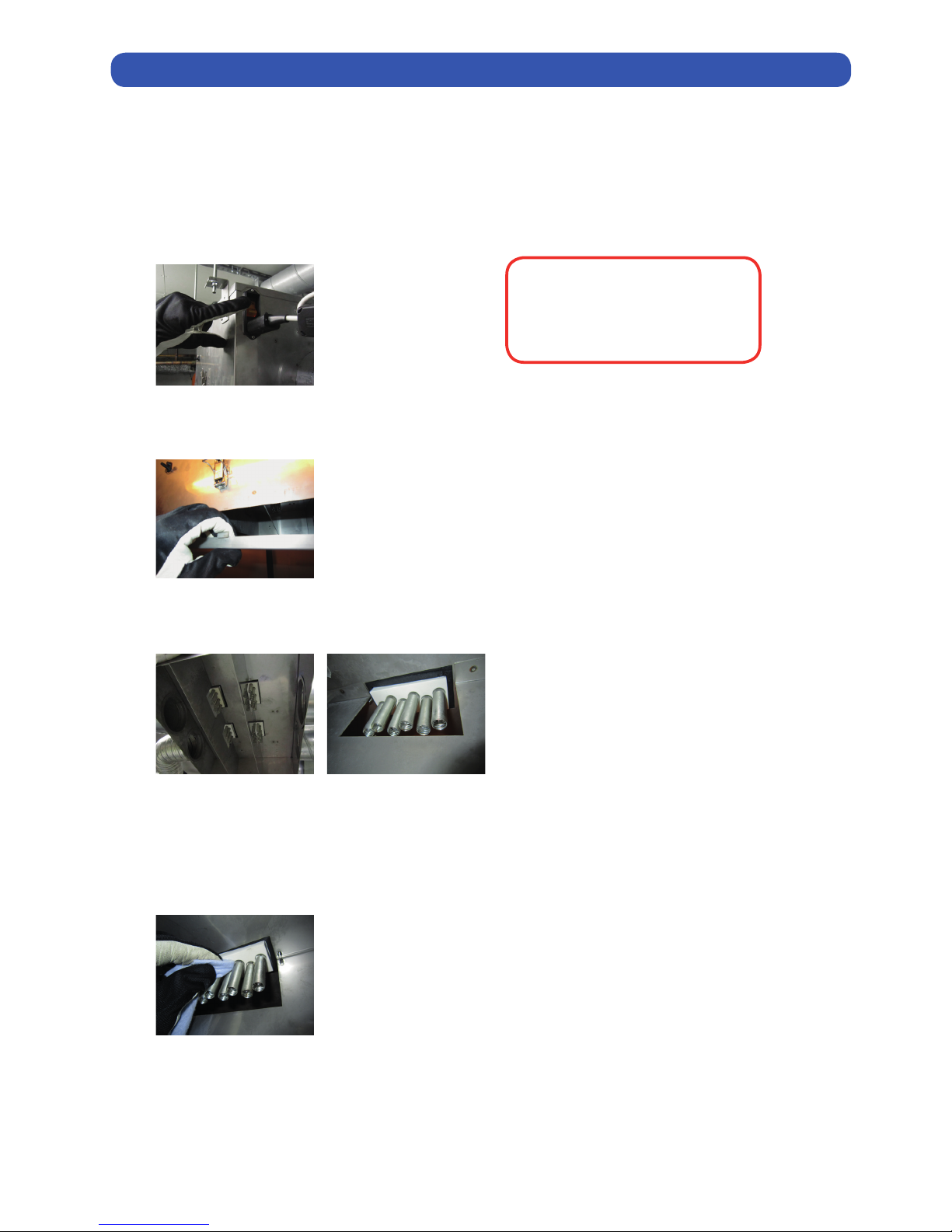
This guide describes a typical installation in a commercial kitchen exhaust duct. The product can also be used
in other applications as long as the specic requirements according to the guide are fullled.
The device may not be used by children or by persons with diminished physical, sensory or mental capacity
or lack of experience and knowledge unless supervised or having received instruction. Supervise children to
ensure that they do not play with the device.

3
1
Central Ventilation (inlet)
2
Damper
3
Inlet tube Ø125 mm
4
AirMaid® Ozone Generator
5
Outlet Tube Ø 80-125 mm
6
Horizontal Exhaust Duct
7
Vertical Exhaust Duct
8
Kitchen Hood
9
90° Tube Ø 80-125 mm
10
Filter Box
2 SYSTEM OVERVIEW
You should carefully study the example installations below. Select the type of installation that works best for you and
that complies with all national standards and regulations. If a central air supply cannot be used, a lter box EU3 class or
higher is required; the air can be supplied from the ceiling space or from the outdoors. In order to reduce the frequency
of lter changes, the supply air should originate from a place containing the least possible impurities. The tempera-
ture of supply air should not exceed 40°C. AirMaid® is very eective in reducing odors provided that the reaction time
between the ozone and the exhaust air in the kitchen duct is at least 2 seconds. This reaction time is important and must
be taken into account during the planning stage.
1
1
2
2
3
3
4
4
5
5
6
6
A A
B B
C C
D D
Designed by Checked by Approved by - date Project
Edition Sheet
/
ITV
Date
Huv 4 (22-05-08)
mikaele 2008-05-22
1 1
25
98
7
6
1
3 4
1
1
2
2
3
3
4
4
5
5
6
6
A A
B B
C C
D D
Designed by Checked by Approved by - date Material
Edition Sheet
/
Date
Huv 7 (25-02-10)
Mikael 2012-11-06
1 1
Scale
Project
10 4 56
7
8
3
SAMPLE TWO
SAMPLE THREE
SAMPLE ONE

4
3 INSTALLATION GUIDELINES
1. Prepare two circular holes in the kitchen duct 6 7 or in the kitchen hood 8 . The diameter of the holes depends
on the diameter of the pipe you select. The diameter of the pipe should be between Ø 80 and 125 mm.
2. Install the ozone generator. 4
The ozone generator must be installed horizontally with the suspension brackets upward and service hatch down-
ward. Use M8 threaded rods and anchor these with nuts on each side of the respective bracket. Note that the mini-
mum installation dimension for the generator is 700x500x450 mm.
AirMaid® 20000 V Exhaust-airow max 10000 m3/h (2800 l/s)
The generator must be easily accessible after installation. Never screw or drill through the generator. Always use the
brackets for suspension.
The duct connection 5 should be no more than 5m long and with a diameter of at least Ø 80 mm. The duct con-
nection must be made of stainless steel (AISI 316). Make sure that the duct does not block any inspection holes.
Note that the direction of the airow must correspond to the arrows on the generator and the picture below.
3. Fasten the outlet tube 5 between the ozone generator and the kitchen duct 6 7 (or the hood 8 ). Make sure
that the connections are properly xed and air-tight.
4. Connect the inlet tube 3 and the IRIS air damper 2 to the ozone generator 4 , or use a lter box with a EU3 lter.
When used with a central air supply, the IRIS air damper is required to achieve the proper airow and pressure.
For more information, see section “5 SYSTEM TEST”.
The exhaust ducts must be swept clean of grease and soot at the time of installation. This is required to achieve the
desired result of the ozone cleaning.
1
1
2
2
3
3
4
4
5
5
6
6
A A
B B
C C
D D
Designed by Checked by Approved by - date Material
Edition Sheet
/
Date
AM 20000V monterings
anv manual 1 (12-12-04)
Mikael 2012-12-04
1 1
Scale
Project
302
616
574
252
404
125
300
To hood or exhaust duct
2 x 30+/-10l/s
(Target: 2 x 35 l/s)
Minimum 1m
Air Damper
To hood or exhaust duct
AirMaid® Ozone Unit
AirMaid® Ozone Unit
Clean Air 2 x 30 +/- 10 l/s (Target: 2 x 35 l/s)

5
The installation must be performed by an authorised electrician and follow national standards and regulations.The in-
terlock device displayed on the diagram below is mandatory. A Typical example of the safety interlock would be to shut
down the main power to the generator when the exhaust fan is shutting down. An all-pole safety switch with a break
length of at least 3 mm must be installed as well. The electrical requirements for the ozone generator are 230V AC and
50 Hz. Each and every generator must be connected to its own 6A fuse.
Remove the four screws that fasten the AirMaid® alarm panel to it’s base. Fasten the base to the wall using devices
suitable for the wall material. In commercial kitchens place the alarm panel where it will be visable to the sta but
not to customers.
NOTE: Upon delivery the generator and alarm panel within the shipping carton are calibrated together and have
matching serial numbers. Make sure that generators are always connected to their own alarm panel.
If you desire to connect AirMaid® to an external monitoring or alarm system, you can accomplish this by connecting it to
the external alarm terminal block within the AirMaid® alarm panel.
NOTE: The maximum load is rated to 250V and 4A.
The earth ground cable is connected to the chassis screw next to the circuit board.
4 ELECRICAL CONNECTION AND SETTINGS
L
N
PE
230 VAC
MAX 6A
Plug & Play
ASSEMBLY AND ELECTRICAL INSTALLATION
EXTERNAL ALARM OUTLET
Connection to external
alarm device.
Voltage freerelay output
NO=Normally open
COM=Common
NC=Normally closed
Outlet power
connection
to generator
Inlet power
connection
from mains
AirMaid® Alarm Panel
Interlocking Device
All-pole Safety Switch
External Alarm Outlet
AirMaid® Ozone Generator
Performed by electrician Plug & Play

6
Once you have adjusted and congured the required airow and under-pressure, you can then apply power to the
generator. The rst time the Alarm panel is started the time and date must be congured.
AirMaid® Running: The GREEN lamp is on. The generator is working in normal mode.
Press to display run and alarm time.
AirMaid® Not Running: The RED lamp is ashing. An error has occurred. Please see the troubleshooting guide under
section ”5 SYSTEM TEST”.
Inspect/Clean: Both the RED and the GREEN lamps are ashing. Contact the service company for a routine
inspection and cleaning of the generator according to the instructions found in this manual.
Call Service: The RED lamp is ashing. An error has lasted for more than 72 hours.
Contact the service company to remedy the error.
Press or to step through menu options or reposition the cursor.
Press or to change the value.
Press to select the current option.
Press for 5 seconds to save the displayed value.
To ENTER the settings menu:
Press once. ”Setup code” will be displayed. Enter 401 on the keyboard.
Press and hold for 5 seconds. The rst menu option, ”Set time”, is now displayed.
To EXIT the settings menu:
Press and to go to ”EXIT MENU”, then press
or wait for 60 seconds and the menu will be closed automatically.
FIRST START
CONFIGURING THE AIRMAID® ALARM PANEL
STATUS OF OPERATION
ENTERING/EXITING THE SETTINGS MENU

7
Press or to step through menu options or reposition the cursor.
Press or to change the value.
Press to select the current option.
Press for 5 seconds to save the displayed value.
SETTINGS OPTIONS (*values that should be set at time of installation)
SETTINGS MENU FLOW DIAGRAM
Text displayed Description of the menu option
* Set time: Set the time.
* Set date: Set the date.
Reset Active Alarm: Reset an active alarm status and restart the functional test.
View event log: View a list of historic events, including alarms and recalibration.
The 100 most recent events will be displayed.
Service Mode: Service Mode ON forces the alarm unit to supply the generator with power for diagnostic
purposes. To end, change to OFF and save. For reasons of safety, Service Mode will automat-
ically exit after one hour.
Set alarm delay: By default, the delay is set to 5 minutes in order to prevent an alarm in case of
a temporary disruption.
Set inspect freq: Service and maintenance interval in months.
Perform Recalibration: This menu option must be used after the generator has been repaired and electronic
components have been replaced. Do not recalibrate at any other time.
EXIT MENU: Leave the settings menu.
AirMaid
RUNNING and
401 5 sec.
Set time:
09:00 and
09:00 5 sec.
Set date:
2012 Mar 01 and
2012 Mar 01 5 sec.
Reset
Active Alarm 5 sec.
View event log
Entries: 000
NR: 01
Service Mode
OFF
OFF / ON 5 sec.
Set alarm delay
Delay time: 005m and
Time: 05m 5 sec.
Set inspect freq
Months: 12 and
Months: 12 5 sec.
Perform
Recalibration
NO / YES 5 sec.
ExIT MENU

8
Measure the airow through the ozone generator and note the value here __________
Measure the pressure inside the ozone generator and note the value here __________
The values above must be entered in the supplied product registration form.
The specied airow must be 30±10 l/s and the specied pressure must be less than -20 Pa (max -10 kPa). Usually the
airow is measured over the damper while the pressure can be measured from the pressure checkpoint on the long side
of the ozone generator.
1. Ensure that the correct airow and pressure is maintained according to the specication.
2. Ensure that the electrical wiring is correctly installed.
3. Ensure that the exhaust fan is running.
4. Ensure that the grease lters are properly installed in the hoods in the kitchen.
5. Ensure that the main power switches are ON (red light must glow) at the ozone generators.
6. Ensure that the interlock is working properly.
7. Ensure that there is no leak in the tubing after the ozone generator.
8. If the ozone generator is installed with a lter box, make sure that the lter is clean.
9. If the system still does not start call the distributor or the manufacturer.
5 SYSTEM TEST
AIRFLOW AND PRESSURE
TROUBLESHOOTING
To hood or exhaust duct
2 x 30+/-10l/s
(Target: 2 x 35 l/s)
Minimum 1m
Air Damper
To hood or exhaust duct
AirMaid® Ozone Unit
AirMaid® Ozone Unit
Clean Air 2 x 30 +/- 10 l/s (Target: 2 x 35 l/s)

9
The ozone cells inside the ozone generator must be checked and if necessary cleaned at least once a year according to
the instructions below. If a separate air lter is used for the inlet air, make sure that this lter is changed at least one time
per year. After a new installation it is anyhow recommended to make an inspection already after three months. Always use
protective gloves and protective goggles.
1. Switch OFF the main power to the ozone generator.
2. Open the service hatch on the bottom of the ozone generator.
3. Make sure that the glass electrodes of the ozone cells are not damaged or cracked.
A proper ozone cell should be clean and free from any mechanical damage according to the picture to the right above.
4. Clean the glass electrodes carefully with a soft towel together with some cleaning spirit. Never use any sharp tools
or abrasive materials for cleaning the glass electrodes.
5. Close the service hatch and switch ON the main power on the ozone generator. Make sure that the generator starts
by checking the alarm panel. If everything works the green lamp will glow. If the red lamp ashes then see –
“TROUBLESHOOTING”.
6 SERVICE AND MAINTENANCE
If any work needs to be performed
in the kitchen extraction ducts, the
power to the ozone generator must
be disconnected.

10
AirMaid® Ozone Capacity (mg/t) Output Pressure drop at 70 l/s Voltage Weight
20000V 20000 400W 130pa 230V/50Hz 24kg
Material: AISI 304 stainless steel
Operating temperature: -25 to +40°C
Dimensions WxLxH: 574x404x252 mm
Sound pressure level (A-weighted) at 1 m: 72,1 dB
The ozone generator is supplied with a pressure and thermal switch. The pressure switch ensures that the ozone genera-
tor only starts when the required negative pressure is established. The thermal switch prevents the ozone generator from
overheating. The main switch is supplied with a thermal overload protection of 2A.
EC DECLARATION OF CONFORMITY
Denna produkt har konstruerats, tillverkats och levererats i enlighet med säkerhetsföreskrifterna i CE direktiven:
• EMC directive 2004/42/EC
• Low voltage directive 2006/95/EC
• Machinery Directive 2006/42/EC
• WEEE Directive 2002/96/EC
This symbol indicates that when the end-user wishes to discard this product, it must be sent to separate
collection facilities for recycling.
Facts about Ozone
Ozone is a colorless gas with a pungent smell that can be detected by any person at a concentration of 0,02ppm (0,4mg/m3).
The smell of ozone is similar to chlorine like in a swimming baths.
Local protection legislations must be followed when using ozone. In Sweden the Swedish Work Environment Authority
issues the following hygienic limits for ozone:
• 0,1ppm (during a working day, 8 hours)
• 0,3ppm (during 15 minutes)
At acute exposure ozone can cause following injuries:
• On skin: Irritation and burning feeling
• In eyes: Hard irritation, burn injuries and reduced vision
• In lungs: Irritated eect on respiratory organs and breathing problems
Basically one should always take precautions if ozone in some way can be detected in indoor environment.
7 TECHNICAL SPECIFICATIONS
1
1
2
2
3
3
4
4
5
5
6
6
A A
B B
C C
D D
Designed by Checked by Approved by - date Material
Edition Sheet
/
Date
AM 20000V monterings
anv manual 1 (12-12-04)
Mikael 2012-12-04
1 1
Scale
Project
302
616
574
252
404
125
300

11
In order to receive the 2-year warranty from the installation date, you have to submit the product registration
form to Interzon within ten (10) days. The easiest way to do this is online at www.interzon.com.
Company Name:
Installed by:
Telephone E-mail:
Name:
Address:
Town: Postal code:
Country:
Email:
Contact name:
Telephone: E-mail:
Product Serial No:
Date of installation: mm/dd/yy
Generator Airow l/s Generator Pressure Pa
8 AIRMAID® PRODUCT REGISTRATION
INSTALLATION/SERVICE COMPANY
PLACE OF INSTALLATION
PRODUCT IDENTIFICATION
FROM SYSTEM TEST
Interzon AB Phono: +46 8 544 444 30
Propellervägen 4A Fax: +46 8 544 444 39
Sweden Internet: www.interzon.com
This form must be sent by email, by fax or online within 10 days from the installation date.

Distributor:
Manufacturer:
Interzon AB Phono: +46 8 544 444 30
Propellervägen 4A Fax: +46 8 544 444 39
SE-183 62 Täby, Stockholm Email: info@interzon.com
Sweden Internet: www.interzon.com
Reproduction, modication or translation without a prior written consent is forbidden with
the exception of what is permitted by the Act on Copyright.
Original instructions
© 2012 Copyright Interzon AB
Edition 2, 05/2013
This manual suits for next models
1
Table of contents
Other AirMaid Air Cleaner manuals

AirMaid
AirMaid 5 000 V Installation and maintenance instructions

AirMaid
AirMaid 2000V Technical Document

AirMaid
AirMaid 5000 T User manual

AirMaid
AirMaid 2 000 V Installation and maintenance instructions

AirMaid
AirMaid 200 W User manual

AirMaid
AirMaid 500 C User manual

AirMaid
AirMaid 10 000 V Installation and maintenance instructions