AirMaid 5 000 V Installation and maintenance instructions

MB
1
Installation and service guide for
AirMaid® V ozone cleaning system
5 000 V
10 000 V
20 000 V
30 000 V
Ai r MA i d ® o z o n e c l e A n i n g s y s t e M
i n n o v A t i v e A i r t r e A t M e n t


MB
3
WARNINGS AND SAFETY NOTICES
General Information
The device may not be used by children or by persons with diminished physical, sensory or mental
capacity or lack of experience and knowledge unless supervised or having received instruction.
Supervise children to ensure that they do not play with the device.
1. This manual contains important information about instructions and safety concerning AirMaid® ozone
generator (hereinafter referred to as the generator). Read this manual carefully before installation,
commissioning or performing service and maintenance on the generator.
2. The generator is intended only for ozone treatment of air in accordance with the instructions in this
manual.
3. The generator uses high voltage to create an electric discharge which generates ozone (O). Ozone sig-
nificantly reduces odours. Absolent CKV AB disclaims any liability if the product is not used according
to the manufacturer’s instructions in this manual.
4. Never clean the generator with chemical cleaning agents. Water or liquid shall not be sprayed onto or
inside the generator. The cleaning of the ozone cell (CGC) shall be done while following the instructions
in this manual.
Troubleshooting and Service Information
1. The user can troubleshoot the generator by following the steps and procedures described in the
System Test section in this manual. If the user needs to have the generator serviced, the user shall
contact the closest authorised service partner or Absolent CKV’s technical support.
2. All repairs on the generator must be performed by a service partner authorised by Absolent CKV AB.
Use a ladder or a stable work platform when installing or servicing the generator if the installation or
service must be done at a height.
The power supply to the generator must be cut off before any service or maintenance.
Make sure that all parts have been installed before you turn on the generator again.
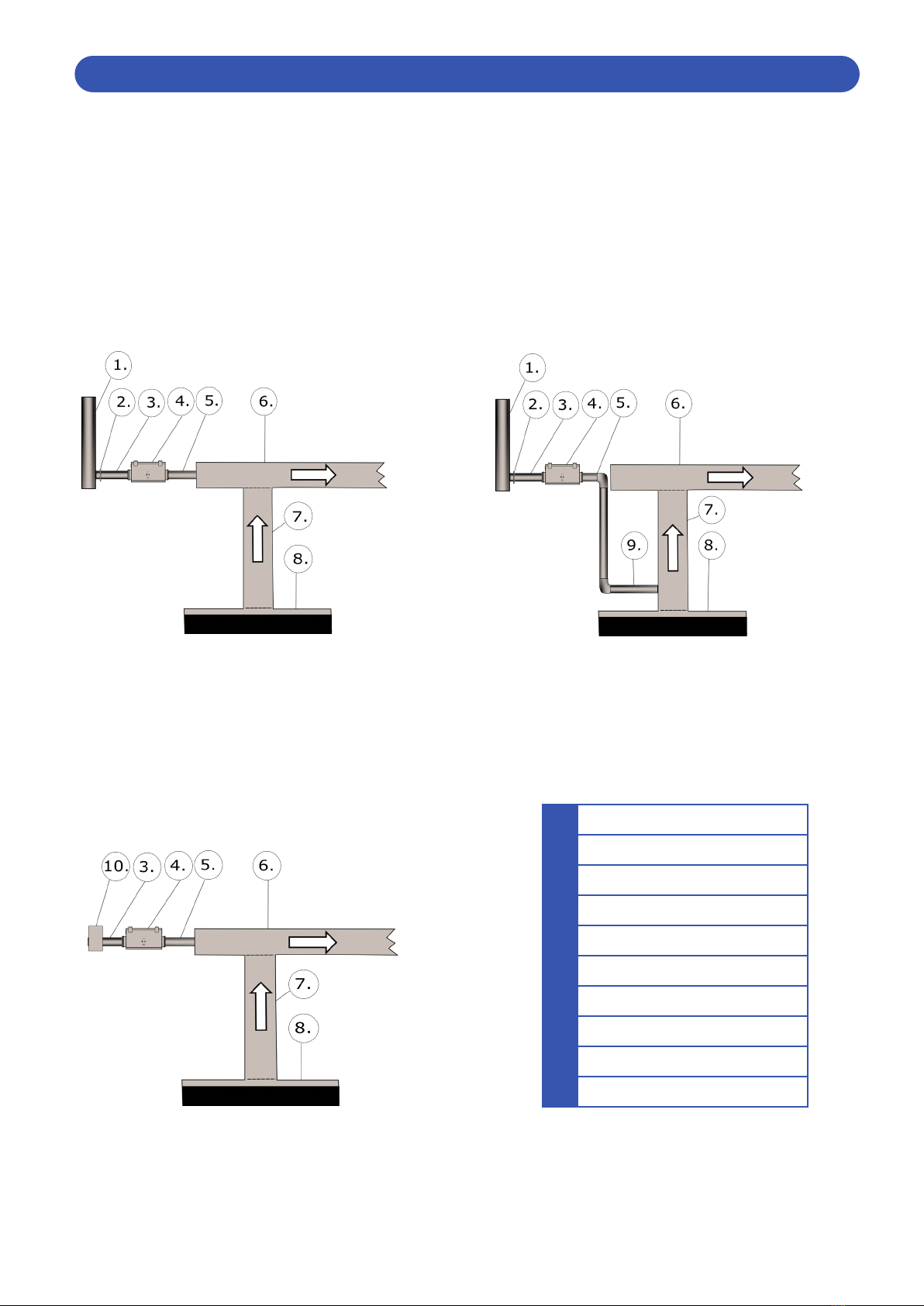
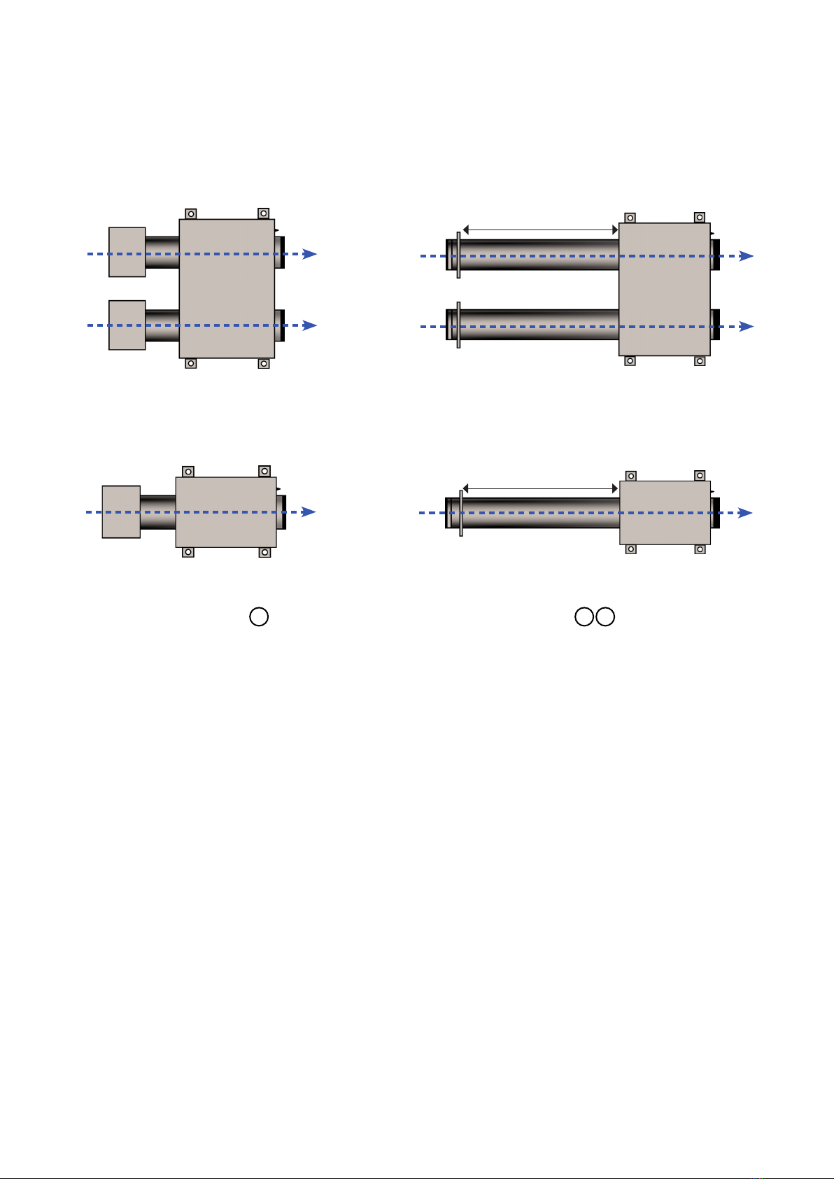
This user manual describes a typical AirMaid® 5000V/10000V/20000V/30000V ozone generator
installation. The installation can vary depending on local rules and regulations relating to building
materials, ventilation systems or the layout of the building/room. Deviations are possible but always
consult the manufacturer before such installation.
The generator produces ozone. If the generator is used by persons who have not read this manual,
there is a risk of injury such as eye or lung irritation. Always follow local regulations and the
recommendations of government organisations that inspect the regulations or the work environment.
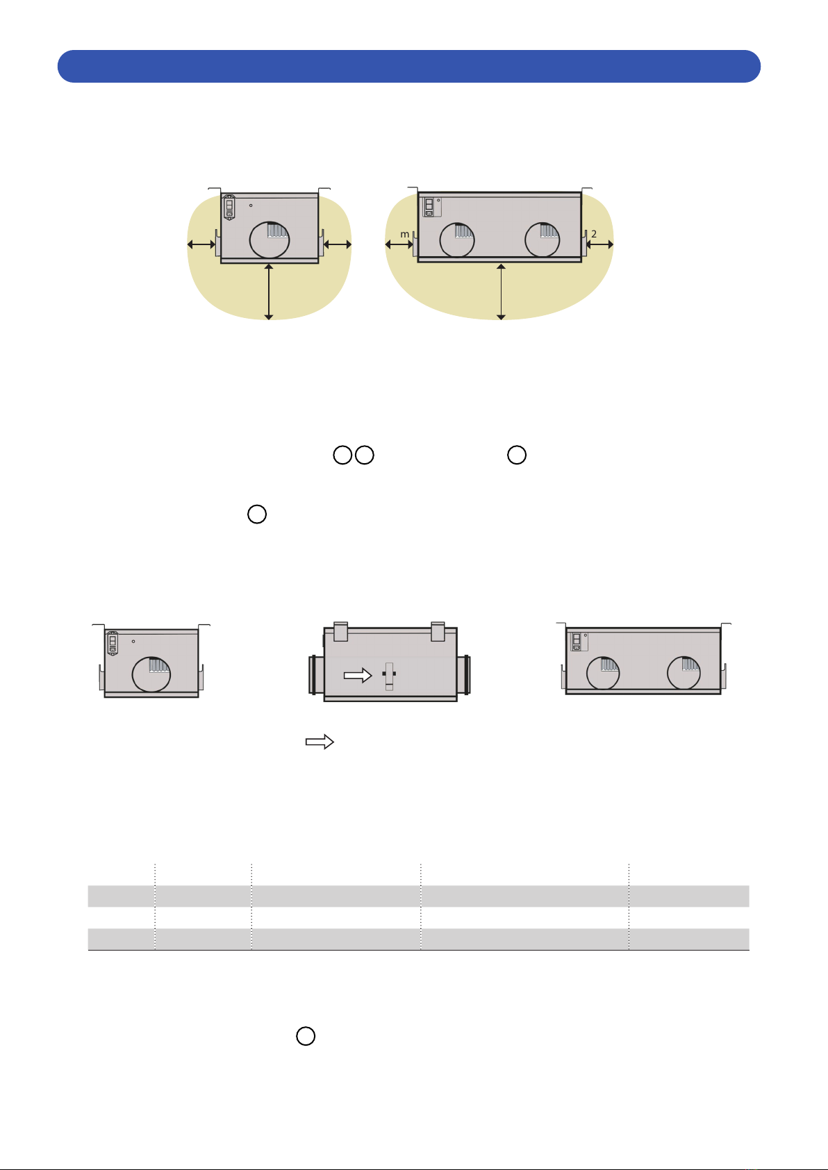
This guide describes a typical installation in a commercial kitchen exhaust duct. The product can also be used
in other applications as long as the specific requirements according to the guide are fulfilled.
The device may not be used by children or by persons with diminished physical, sensory or mental capacity
or lack of experience and knowledge unless supervised or having received instruction. Supervise children to
ensure that they do not play with the device.

MB
4
1. Check Product
2. System Overview
3. Installation Guidelines
4. Electrical Connection and Settings
5. BACnet Connection and Settings
6. AirMaid® Startup
7. System Test
8. Service and Maintenance
9. Technical Specifications
Check that the shipment consists of the components below and that there are no visible damages. Any discrepancy
must always be reported to the distributor or manufacturer. Read through the complete guide before starting the
installation.
1 x AirMaid® Ozone Generator 1 x AirMaid® Alarm Panel
TABLE OF CONTENTS
1 CHECK PRODUCT
LIMITED WARRANTY FOR Absolent CKV EQUIPMENT
This warranty is subject to the following conditions.
A new product is warranted to be free from defects and workmanship for a period of 3 years from the first
delivery date. If a product registration is submitted to Absolent CKV within ten (10) days after the installation is
completed, the warranty will instead take effect from the date of installation.
A spare part is warranted to be free from defects and/or workmanship for a period of ninety (90) days from the
date of the original installation.
The warranty for new equipment covers the repair or replacement of the defective part and includes labor
charges according the recommended hours by Absolent CKV and maximum kilometer charges of 300 km round
trip.
The warranty for spare parts covers only the repair or replacement of the defective part and does not include any
labor charges for the removal and installation of any parts, travel or other expenses incidental to the repair or
replacement of a part.
Any claim must be presented to either Absolent CKV or the distributor from whom the product was purchased.
No allowance will be granted for repairs made by anyone else without Absolent CKV written consent. If damage
occurs during shipping, notify the sender at once so that a claim can be filed.
The above limited warranty does not apply to damage resulting from accident, alteration, misuse or if the serial
number is removed or defaced.
3-YEAR PRODUCT WARRANTY
Submit the product registration form to Absolent CKV within ten (10) days after the
completion of the installation in order to receive a 3-year warranty. The warranty will then
be valid from the installation date. The easiest way to do so is by scanning the QR-code the
right and submitting the form. The whole process will only take a couple of minutes.

MB
5
1
Central Ventilation (inlet)
2
Damper
3
Inlet tube Ø125 mm
4
AirMaid® Ozone Generator
5
Outlet Tube Ø 80-125 mm
6
Horizontal Exhaust Duct
7
Vertical Exhaust Duct
8
Kitchen Hood
9
90° Tube Ø 80-125 mm
10
Filter Box (EU3 class or higher)Filter Box (EU3 class or higher)
2 SYSTEM OVERVIEW
You should carefully study the example installations below. Select the type of installation that works best for you and
that complies with all national standards and regulations. If a central air supply cannot be used, a filter box EU3 class or
higher is required; the air can be supplied from the area above a false ceiling or from the outdoors. In order to reduce
the frequency of filter changes, the supply air should originate from a place containing the least possible impurities.
The temperature of supply air should not exceed 40°C. AirMaid® is very effective in reducing odors provided that the
reaction time between the ozone and the exhaust air in the kitchen duct is at least 3 seconds. This reaction time is
important and must be taken into account during the planning stage.
SAMPLE TWO
SAMPLE THREE
SAMPLE ONE

MB
6
3 INSTALLATION GUIDELINES
There has to be a gap of about 20 cm on all sides of the ozone generator for disassembly where applicable. Also, the
service hatch opening at the bottom of the ozone generator must be accessible, so that it can be removed easily for
annual service and maintenance.
1. Prepare a circular hole in the exhaust duct 6 7 or in the kitchen hood 8 . The diameter of the hole is depended
on the tube you select. The diameter must be between Ø 80-125 mm. The inlet and outlet pipes on the ozone gen-
erator have a diameter of Ø125mm.
2. Install the ozone generator. 4
The ozone generator must be installed horizontally with the suspension brackets upward and service hatch down-
ward. Use M8 threaded rods and anchor these with nuts on each side of the respective bracket.
Note that the direction of the airow must correspond to the arrows on the generator and the pictures below.
Make sure that you have selected the correct ozone generator.
AirMaid Ozone Capacity
Up to
Max Treated Exhaust
Use parallel units for higher airflow
Airflow through the ozone generator
Specification Target
Pressure Drop
(P @ Target Airflow rate)
5000V 5000 mg/h 2500 m3/h (700 l/s) 10–25 l/s 15 l/s 78Pa
10000V 10000 mg/h 5000 m3/h (1400 l/s) 20–40 l/s 30 l/s 130Pa
20000V 20000 mg/h 10000 m3/h (2800 l/s) 40–80 l/s 60 l/s 89Pa
30000V 30000 mg/h 15000 m3/h (4200 l/s) 60–120 l/s 90 l/s 110Pa
The generator must be easily accessible after installation. Never screw or drill through the generator. Always use the
brackets for suspension.
The length of the ozone outlet tube 5 can be maximum 5 m. The minimum dimension of the ozone outlet tube
can go down to Ø 80 mm. The material of the ozone outlet tube must be stainless steel (AISI 316). Make sure that
the tube is not blocking any inspection hatches.
Note that the direction of the airow must correspond to the arrows on the generator and the picture below.
AirMaid
5000V
10000V
AirMaid
20000V/30000V
All electronics in the ozone generator can be reached from above the ozone generator and from inside the service hatch,
so we recommend additional space around it to facilitate on-site repairs without the need to dismantle the generator
first. The ozone generator should be placed in such a way that it can be easily reached using a ladder or servicing
platform.
free access
20 cm20 cm
free access
20 cm 20 cm

MB
7
3. Fasten the outlet air tube 5 between the ozone generator and the exhaust duct 6 7 (or the hood). Make sure
that all connections are properly xed and sealed.
SPLITTING 20000V/30000V OUTLET PIPES BETWEEN DUCTS (OPTIONAL)
As the AirMaid 20000V generator has two outlet pipes, it is possible to share the generated ozone between two nearby
sections of the exhaust duct system. Because each duct section can have a unique pressure, it is the responsibility of the
engineer to ensure the proper airow is delivered into each section of channel.
MOUNTING THE IRIS DAMPER
The iris damper should be installed at appropriate distance from sources of disturbance, according to the specied as-
sembly specications for the specic model. This applies to all types of tting, whether it is a T-pipe, bend or dimensional
change.
FILTER BOX INSTALLATION CENTRAL AIR INSTALLATION
2 x Filter box
Filtered air is required. Remember to add a filter
inspection/replacement to the maintenance schedule.
With central air installations, IRIS dampers are usually
necessary to obtain the proper airflow and static pressure.
Clean Air
5000V 10–25 l/s (Target: 15 l/s)
10000V 20–40 l/s (Target: 30 l/s)
Minimum 1 m
Minimum 1 m
Clean Air
20000V 20–40 l/s per pipe (Target: 30 l/s)
30000V 30–60 l/s per pipe (Target: 45 l/s)
2 x Iris dampers

MB
8
ASSEMBLY
Remove the four screws that fasten the AirMaid® alarm panel to it’s base. Fasten the base to the wall using devices
suitable for the wall material. In commercial kitchens place the alarm panel where it will be visable to the staff but
not to customers.
NOTE: Upon delivery the generator and alarm panel within the shipping carton are calibrated together and have
matching serial numbers. Make sure that generators are always connected to their own alarm panel.
ELECTRICAL INSTALLATION
The installation must be performed by an authorized electrician and follow national standards and regulations. The
interlock device displayed on the diagram below is mandatory. A typical example of the interlock would be to shut
down the main power to the generator when the exhaust fan is shutting down. Another example would be to
remotely shut down the main power to the generator through BACnet. An all-pole safety switch with a break length
of at least 3 mm must be installed as well. The electrical requirements for the ozone generator are 230V AC and 50-
60 Hz. Each and every generator must be connected to its own slow fuse, 6A for the 5000V/10000V and 10A for the
20000V/30000V.
EXTERNAL ALARM OUTLET
If you desire to connect AirMaid® to an external monitoring or
alarm system, you can accomplish this by connecting it to the
external alarm terminal block within the AirMaid® alarm panel.
NOTE: The maximum load is rated to 250V and 4A.
4 ELECTRICAL CONNECTION AND SETTINGS
Connection to external alarm
device. Voltage freerelay output
NO = Normally open
COM = Common
NC = Normally closed
Important!
Under no circumstances may the cable between the alarm panel and generator be used for any external
electrical connections or control signaling.
Important!
If the electrical cables are removed during
installation, ensure that they are properly
reconnected to the “IN” L/N terminals.

MB
9
5 BACNET CONNECTION AND SETTINGS OPTIONAL
Product Description: This addon card receives data in JSON –form from the Airmaid panel and makes it visible to
other BACNet devices in the same BACNet network.
BACnet Standardized Device Profile (Annex L): BACnet Application Specific Controller (B-ASC).
List all BACnet Interoperability Building Blocks
Supported (Annex K):
• Data Sharing-ReadProperty-B (DS-RP-B)
• Data Sharing-WriteProperty-B (DS-WP-B)
• Device Management-Dynamic Device Binding-B (DM-DDB-B)
• Device Management-Dynamic Object Binding-B (DM-DOB-B)
• Device Management-DeviceCommunicationControl-B (DM-DCC-B)
Standard Object Types Supported: • Device Object
• Analog Value Object
• Binary Value Object
• Multi-State Value Object
Data Link Layer Options: MS/TP master (Clause 9), baud rate(s): 9600, 19200, 38400, 57600, 76800, 115200.
Device Address Binding:Is static device binding supported?
- No.
Networking Options: Does the BBMD support registrations by Foreign Devices?
- No.
Does the BBMD support network address translation?
- No.
Network Security Options: Non-secure Device - is capable of operating without BACnet Network Security.’
Character Sets Supported: ISO 10646 (UTF-8).
Vendor Name: Bithouse Oy
Product Name: Absolent CKV AirMaid BACnet MS/TP Addon Card

MB
10
SYSTEM STATUS
1 Unknown
2 Running
3 Please Call Service
4 Inspect / Clean
5 Oine: Not Connected
6 Oine: Pressure
7 Calibration Fail: Pressure
8 Remotely Disabled
OPTIONS
INSPECTION INTERVAL Service and maintenance interval in months.
SET INSPECTION INTERVAL Change Present Value between 1-12. Default 12 months.
TIME LEFT TO INSPECTION Default 360 days.
ALARM DELAY The delay time before we receive an alarm if a component failure occurs.
SET ALARM DELAY Change Present Value between 2s-24h. Default 2s.
PFNC The delay time before we receive an alarm about a pressure issue or that the
unit is switched o.
SET PFNC Change Present Value between 2s-24h. Default 5min.
EVENT LOG POSITION The amount of events that haver been logged.
POWER, CALIBRATED The current value that the alarm panel is calibrated to.
POWER, ACTIVE The actual value that the alarm panel has detected.

MB
11
6 AIRMAID STARTUP
Once you have adjusted and configured the required airflow and under-
pressure, you can then apply power to the generator. The first time the alarm
panel is started the time and date must be configured.
Press or to step through menu options or reposition the cursor.
Press or to change the value.
Press to select the current option.
Press for 5 seconds to save the displayed value.
ENTERING/EXITING THE SETTINGS MENU
To ENTER the settings menu:
Press once. ”SETUP CODE”will be displayed. Enter 401 on the keyboard.
Press and hold for 5 seconds. At this time "SET TIME"will appear and you may use the and keys to traverse
within the settings menu to perform the necessary tasks.
To EXIT the settings menu:
Press or to go to ”EXIT MENU”, then press or wait 60 seconds and
the menu will be closed automatically.
STATUS OF OPERATION
RUNNING: Green lamp is on solid. Normal operation.
INSPECT/CLEAN: Green lamp is blinking. Contact your service company for a routine inspection and
cleaning of the generator as described in this guide.
PLEASE CALL
FOR SERVICE
The generator is operating, however it is not running at full for service capacity. Partial
failure: Red lamp is blinking, green is on solid. Severe failure: Only the red lamp is
blinking (from version 3.01).
AIRMAID OFFLINE
SYSTEM PRESSURE
Red lamp is blinking. The system has detected a problem with the static pressure. The
grease lters in the kitchen hood may not be installed correctly, or the extract air fan is
switched o or the inspection hatches are open (from version 3.01).
AIRMAID OFFLINE
NOT CONNECTED
Red lamp is blinking. The generator is not switched on. The main switch on the
generator may be turned o, or perhaps the power supply cable from the Alarm Panel
is not connected to the generator (from version 3.01).
CALIBRATION FAIL
NOT CONNECTED
Red lamp is blinking. A calibration was performed while the generator was not
running. The main switch on the generator may be turned o, or perhaps the power
supply cable from the Alarm Panel is not connected to the generator (from version
3.01).
CALIBRATION FAIL
AIRMAID PRESSURE
Red lamp is blinking. A calibration was attempted while the system detected a
problem with the static pressure. The grease lters in the kitchen hood may not be
installed correctly, or the extract air fan is switched o or the inspection hatches are
open (from version 3.01).
3-YEAR PRODUCT WARRANTY
REMEMBER to submit the product registration form to Absolent CKV within ten (10) days
after the completion of the installation in order to receive a 3-year warranty. The warranty
will then be valid from the installation date. The easiest way to do so is by scanning the
QR-code the right and submitting the form. The whole process will only take a couple of
minutes.

MB
12
SETTINGS OPTIONS (*values that should be set at time of installation)
SETTINGS MENU FLOW DIAGRAM
Text displayed Description of the menu option
* SET TIME: Set the time.
* SET DATE: Set the date.
VIEW EVENT LOG: View a list of historic events, including alarms and recalibration. The 100 most recent
events will be displayed
SET ALARM DELAY: The delay time before we receive an alarm if a component failure occurs. By default,
this delay is set to 2 seconds (from version 3.01).
SET PF-NC DELAY: The delay time before we receive an alarm about a pressure issue or that the unit is
switched o. By default, this delay is set to 5 minutes (from version 3.01).
SET INSP/CLEAN: Service and maintenance interval in months.
PERFORM RECALIBRATION: This menu selection may only be performed after a repair.
PERFORM HARD RESET: Performs a hard reset of the alarm panel that temporarily shuts down the unit for 5
seconds (from version 3.01).
EXIT MENU: Exit the settings menu.
AIRMAID
RUNNING and
401 5 sec.
SET TIME:
09:00 and
09:00 5 sec.
SET DATE:
2023 Jan 01 and
2023 Jan 01 5 sec.
VIEW EVENT LOG
NR: 001
*See the following
page for more infor-
mation
SET ALARM DELAY
DELAY TIME: 2s
and
Default: 2s 5 sec.
SET PF-NC DELAY
DELAY TIME: 5m and f
Default: 5m 5 sec.
SET INSP/CLEAN
MONTHS: 12 and
Default: 12 5 sec.
PERFORM
RECALIBRATION
NO / YES 5 sec.
PERFORM HARD
RESET
EXIT MENU

MB
13
EVENT LOG
KEYPAD FUNCTIONS
INSPECT/CLEAN
Press to display days how many days remain until the next inspecton.
DISMISS REMINDER: Press and hold for 5 seconds to dismiss the reminder message on the display.
RESET REMINDER: Enter 222, then press and hold for 5 seconds to reset the the reminder timer
(perform this if cleaning is performed before the timed reminder is displayed)
CAUSE
A = Alarm
C = Calibration
P = Pressure Fault
N = Not Connected (ozone generator not detected)
D = System Remotely Disabled (Interlock by BACnet)
3.
4. 5.
2.1.
INFORMATION ABOUT THE ALARM PANEL
RUN/ALARM TIME FUNCTIONS
Press to display Run time and alarm time since initial installation.
1: Number of registered events 2: Cause 3: Event Duration 4: When (Year/month/day) 5: When (Time)
Press to display Alarm Panel Hardware and Firmware versions.
SYSTEM LOAD INFORMATION
Press to display system load values pCalib and pActive. These are diagnostic values that can assist your AirMaid
authorized service company to troubleshoot system errors (from version 3.01).

MB
14
Measure the airflow through the ozone generator and note the value here __________
Measure the pressure inside the ozone generator and note the value here __________
The values must be transferred to the attached product registration.
The specified airflow must be 10–25 l/s for the 2000V/5000V, 20–40 l/s for the 10000V, 40–80 l/s for the 20000V and
60–120 l/s for the 30000V. The specified pressure must be less than -25 Pa (max -500 Pa). Usually the airflow is measu-
red over the damper while the pressure can be measured from the pressure checkpoint on the short side of the ozone
generator.
TROUBLESHOOTING
1. Ensure that the correct airflow and pressure is maintained according to the specification.
2. Ensure that the electrical wiring is correctly installed.
3. Ensure that the exhaust fan is running.
4. Ensure that the grease filters are properly installed in the hoods in the kitchen.
5. Ensure that the main power switches are ON (orange light must glow) at the ozone generators.
6. Ensure that the interlock is working properly.
7. Ensure that there is no leak in the tubing after the ozone generator.
8. If the ozone generator is installed with a filter box, make sure that the filter is clean.
9. Reset the active alarm, see section“6 AIRMAID STARTUP”.
10. If the system still does not start call the distributor or the manufacturer.
7 SYSTEM TEST
AIR FLOW AND PRESSURE
1X 15 L/S TARGET
2000V/5000V
1X30 L/S TARGET
10000V
2X30 L/S TARGET
20000V
INLET INLETINLET
Pressure Check Point Pressure Check Point
2X45 L/S TARGET
30000V
3-YEAR PRODUCT WARRANTY
REMEMBER to submit the product registration form to Absolent CKV within ten (10) days
after the completion of the installation in order to receive a 3-year warranty. The warranty
will then be valid from the installation date. The easiest way to do so is by scanning the
QR-code the right and submitting the form. The whole process will only take a couple of
minutes.

MB
15
The ozone cells inside the ozone generator must be checked and if necessary cleaned at least once per year according
to the instructions below. If a separate air filter is used for the inlet air, make sure that this filter is changed at least one
time per year. With a new installation it is recommended to perform a first inspection after three months.
8 SERVICE AND MAINTENANCE
If any work needs to be performed in the
kitchen extraction ducts, the power to the
ozone generator must be disconnected.
Switch OFF the main power to the ozone generator and then remove the service hatch from the bottom of the
ozone generator.
Note: AirMaid® 2000V/5000V has one set
of ozone cells; 10000V has two sets; and
20000V has four sets and 30000V has six
sets.
Make sure that the glass electrodes of the ozone cells are not damaged or cracked. A proper ozone cell should be
clean and free from any mechanical damage according to the picture to the right above.
Caution! the glass tubes are fragile!
Use only your hands and never any
sort of tool to scrape or clean the
ozone cell.
Wet a soft, durable cleaning
cloth with your alcohol-based
cleaning spirit. Never spray
directly onto the ozone cell!
Finally, wipe clean the inside of the chassis.
Note: Remember to check the mesh
filter(s) and wash them if necessary.
(Spare filter(s) can be ordered from
Absolent CKV).
Put the service hatch back on and turn ON the main switch on the generator. Within a few minutes the green light
on the alarm panel should light up, this indicates that the generator is back on.
First clean the surfaces of the glass
eletrodes and then around the base of
the cell. Using your fabric like dental floss,
gently clean between the electrodes with a
gentle sliding movement.

MB
16
AirMaid Ozone Capacity
Up to
Power Voltage Main
Breaker
Dimensions Weight
2000V 2000 mg/h 100 W 230V/50-60 Hz 6A Slow 300 x 402 x 252 mm 10 kg
5000V 5000 mg/h 100 W 230V/50-60 Hz 6A Slow 300 x 402 x 252 mm 10 kg
10000V 10000 mg/h 200 W 230V/50-60 Hz 6A Slow 300 x 402 x 252 mm 12 kg
20000V 20000 mg/h 400 W 230V/50-60 Hz 10A Slow 572 x 402 x 252 mm 24 kg
30000V 30000 mg/h 500 W 230V/50-60 Hz 10A Slow 838 x 402 x 252 mm 25 kg
Material: AISI 304 stainless steel Operating temp: -25º to +40ºC
For air flow and pressure specifications, see section 3, “INSTALLATION GUIDELINES”.
9 TECHNICAL SPECIFICATIONS
The ozone generator is supplied with a pressure and thermal switch.
The pressure switch ensures that the ozone generator only starts
when the required negative pressure is established. The thermal
switch prevents the ozone generator from overheating. The main
switch for the 2000V/5000V/10000V is supplied with a thermal over-
load protection of 2A and the main switch for the 20000V/30000V is
suppled with a thermal overload protection of 4A.
Facts about Ozone
Ozone is a colorless gas with a pungent smell that can often be detected by any person at a concentration of 0,02ppm (0,4mg/m
3
). The smell of ozone
is similar to chlorine like in a swimming pool.
Local protection legislations must be followed when using ozone. In Sweden, for example, the Swedish Work Environment Authority issues the follow-
ing hygienic limits for ozone:
• 0,1ppm (during a working day, 8 hours)
• 0,3ppm (during 15 minutes)
At acute exposure ozone can cause following injuries:
• On skin: Irritation and burning feeling
• In eyes: Hard irritation, burn injuries and reduced vision
• In lungs: Irritated effect on respiratory organs and breathing problems
Always take corrective action and safety precautions if ozone is detected in an indoor environment.
EC DECLARATION OF CONFORMITY
This product has been designed, constructed and distributed in compliance with the
safety requirements of EC Directives:
• EMC directive 2014/30/EU
• Low voltage directive 2014/35/EU
This symbol indicates that when the end-user wishes to discard this
product, it must be sent to separate collection facilities for recycling.
20000V
252
252
572
125
125
2000V/5000V/10000V
252
252
572
125
125
30000V
231
The AirMaid V ozone generators comply with EN 16282-8:2017 »Equipment in commercial kitchens – elements for ventilation (Part 8)
The European Standard EN16282 for the ventilation of commercial kitchens sets requirements for air-fed ozone generators in order to limit the pro-
duction of nitrogen oxides and nitric acid. The standard stipulates that oxygen-fed systems are used with a total extraction volume of more than 2500
m3/h. The air-fed AirMaid V generators meet this requirement. Each CGC ozone cell installed in the generators, which is surrounded by a volume ow
of up to 54 m3/h, can only clean up to 2500 m3/h total extraction volume. Even with larger total extraction volumes, the AirMaid V generators can
therefore be used safely, even if they are not oxygen-fed.


Distributor:
Manufacturer:
Absolent CKV AB Email: info@absolentckv.com
Propellervägen 4A Internet: www.airmaid.com
SE-183 62 Täby, Stockholm
Sweden
Reproduction, modication or translation without a prior written consent is forbidden with the
exception of what is permitted by the Act on Copyright.
Original Instructions
Copyright Information
© 2023 Copyright Absolent CKV AB
Edition 9 01/23
This manual suits for next models
3
Table of contents
Other AirMaid Air Cleaner manuals

AirMaid
AirMaid 10 000 V Installation and maintenance instructions

AirMaid
AirMaid 2 000 V Installation and maintenance instructions

AirMaid
AirMaid 500 C User manual

AirMaid
AirMaid AirMaid V Installation and maintenance instructions

AirMaid
AirMaid 200 W User manual

AirMaid
AirMaid 5000 T User manual

AirMaid
AirMaid 2000V Technical Document
Popular Air Cleaner manuals by other brands

Kogan
Kogan SmarterHome 1S user guide

GLOBAL PLASMA SOLUTIONS
GLOBAL PLASMA SOLUTIONS GPS-2400 Installation, operation & maintenance manual

Perenio
Perenio IONIC SHIELD Installation and operation manual

AllerAir
AllerAir AirMedic Exec Technical specifications

Nu-Calgon
Nu-Calgon iWave-C Instruction bulletin

Stylies
Stylies Pegasus manual