Airmar NMEA 0183 to USB Combiner Instruction Manual

1
NMEA 0183 to USB
Combiner
for WeatherStation®Instrument
GPS Receiver
Heading Sensor
Owner’s Guide & Installation Instructions
Part No.___________ Date of Purchase__________
17-492-01 rev.04 08/10/12

2
All Rights Reserved. Except as expressly provided herein, no part of this manual may be
reproduced, copied, transmitted, disseminated, downloaded, or stored in any storage
medium, for any purpose without prior written consent of Airmar. Airmar hereby grants
permission to download a single copy of this manual and of any revision of this manual onto
a hard drive or other electronic storage medium to be viewed and to print one copy of this
manual or any revision hereto, provided that such electronic or printed copy of this manual
or revision must contain the complete text of this copyright notice and provided further that
any unauthorized commercial distribution of this manual or any revision hereto is strictly
prohibited.
Information in this manual is subject to change without notice. Airmar reserves the right to
change or improve its products and to make changes in the content without obligation to
notify any person or organization of such changes. Visit the Airmar website at
www.airmar.com for current updates and supplemental information concerning the use and
operation of this and other Airmar products.
Copyright © 2008 - 2012 Airmar Technology Corp. All rights reserved.

3
Follow the safety precautions below to reduce the risk of poor product
performance, property damage, personal injury, and/or death.
WARNING: Always wear safety goggles and a dust mask when installing.
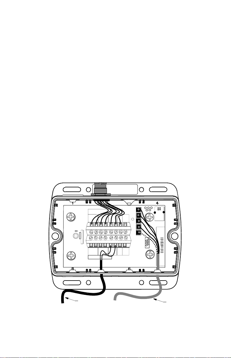
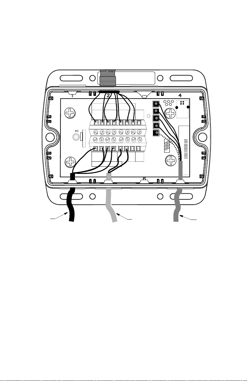
WARNING: The power supply must be OFF before making electrical connections.
WARNING: The power supply voltage must be within the Combiner’s operating
voltage range of 10 to 28 VDC. And the power supply voltage must be within the
operating voltage range specified for any connected sensor(s).
WARNING: A safe installation requires a 0.5 amp fast-blow fuse or circuit breaker.
Except, WeatherStation models with a heater require a 3 amp fast-blow fuse or
circuit breaker.
WARNING: Make power connections to a power source that is isolated from the
engine start battery(s). Voltage drops may cause the instrument/receiver/sensor
to lose information and/or change operating mode.
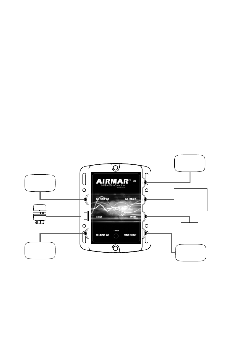
CAUTION: Do not remove the Airmar waterproof connector(s) to ease cable
routing.
CAUTION: To reduce electrical interference from other electrical wiring and any
on-board equipment with strong magnetic fields such as radar equipment, radio
transmitters, boat engines, generators, etc., separate the cables by at least 1m (3').
Ensure that all the cable shields are appropriately grounded.
CAUTION: Be careful not to tear the cable jackets when passing them through
bulkheads and other parts of the boat. Use grommets to prevent chaffing.
CAUTION: Use a multimeter to check the polarity and the connections to the
power supply before applying power to the instrument/receiver/sensor.
CAUTION: Coil any excess cable(s) and secure with cable ties to prevent
damage.
IMPORTANT: All display devices must be NMEA 0183.
IMPORTANT: Please read the instructions completely
before proceeding with the installation. These instructions
supersede any other instructions if they differ.

4
Applications
• Allows Airmar sensor data to be displayed simultaneously on both an NMEA
0183 display and a PC.
• Two auxiliary grommets labeled AUX NMEA OUT can be used to connect
additional devices capable of displaying sensor data.
Specifications
• All display devices must be NMEA 0183.
• RS422 or RS485 interface
• Fast-blow fuse or circuit breaker: 0.5 amp
• Combiner power supply voltage: 10 - 28 VDC
• Sensor power supply voltage: The power supply voltage must be within the
operating range specified for any connected sensor. You can find the operating
voltage range for your sensor(s) on the Airmar website. Go to http://
www.airmar.com and search for your sensor model on the home page. When
the Search Results appear, click on the image. When the product screen
appears, click on Brochure / Specifications. The Supply Voltage range is on the
second page.
Baud Rate
38,400
Tools & Materials
Safety goggles
Dust mask
Pencil
Electric drill
Drill bit: 3mm or 1/8”
Grommet(s) (some installations)
Cutting pliers
Phillips screwdrivers
Alcohol (optional)
Wire strippers
Heat-shrink tubing
Heat gun
Blade screwdrivers
Multimeter
Cable ties (some installations)

5
Connecting to a Combiner
What does NMEA IN and NMEA OUT mean?
NMEA IN represents input for data flowing into an NMEA device. An IN device is
an NMEA listener. NMEA OUT signifies output for data flowing out of a device.
OUT devices are NMEA talkers. The Combiner label designates data flow as
viewed by the device itself. For example, the Combiner’s output should be
connected to a display’s input.
The output of any NMEA device (talker) may connect to the inputs of multiple
devices (listener). However, it is not permissible to connect the output of one
NMEA device to the output of another. If the need arises to provide data from the
outputs of two or more devices to the input of a given device, then a Combiner is
required.
CAUTION: Be sure to connect an NMEA talker to the NMEA IN terminal and
NMEA listeners to the NMEA OUT terminals.
CAUTION: When connecting NMEA devices to one another, the cable shield only
connects at ONE end of the cable, preferably at the device providing the NMEA
output.
power
supply
NMEA display
Airmar
or other sensor
Figure 1. Combiner installation (WeatherStation instrument shown)
additional
display
additional
display
Weather
or additional
Smart™ Sensor
PC
sensor
Station
Copyright © 2008, 2009 Airmar Technology Corp.

6
Mounting Location of the Combiner
1. Select a convenient, dry, mounting location for the water-resistant Combiner, a
minimum of 1m (3') from the NMEA device and the PC.
2. Hold the Combiner at the selected location and mark the position of the screw
holes.
NOTE: If the Combiner will be mounted on a vertical surface, face the
grommets to the sides to avoid water seeping into the box.
3. At the marked locations, drill the holes. Do not fasten the Combiner in place at
this time.
Instrument/Receiver/Sensor Cable
Route the instrument/receiver/sensor cable to the Combiner. Do not connect the
cable or fasten it in place at this time.
USB Cable
Route the USB cable coming from the Combiner to the USB port on the PC.
Do not connect the cable or fasten it in place at this time.
NMEA Display/Additional Sensor Cable
1. Route the cable coming from the NMEA display/additional sensor to the
Combiner. Do not fasten the cable in place at this time.
2. Allowing an extra 25 cm (10") for wiring ease, cut the cable to length.
3. Remove the cover of the Combiner to expose the terminals inside (see Figure 2).
Figure 2. Inside the Combiner
AIRMAR
WEA
THERSTA
TION
25-431-01
NMEA DISPLAY
ACTIVERESEARCHL
TD2005
C
SHIELD
A/+ B/- A/+ B/ - + A/+
NMEAIN
NMEAOUT
POWER
NMEA
IN
SHIELD
NMEA IN
NMEAOUT
POWER
NMEA
IN
- +
B/-
B/-A/+B/-A/+
USB
050818-001 ACTIS
SHIELD
PWR
GND
DM
DP
NMEAMUL
TIPLEXER
power PC
cable cable
Copyright © 2007 Airmar Technology Corp.

7
4. Using a small Phillips screwdriver, puncture the grommet that corresponds to
NMEA Display on the cover (see Figure 1). Be careful not to damage the circuit
board.
5. Push approximately 100 mm (4") of the cable through the grommet (see
Figure 3). To ease sliding, apply alcohol to the cable jacket.
6. Strip 60mm (2-1/2") of the outer jacket and foil shielding from the cut end of the
cable.
7. Strip 10mm (3/8") of conductor insulation from the end of each colored wire.
8. Protect the cable’s foil shielding from causing a short by using heat-shrink
tubing around the jacket where the wires emerge from the cable. The tubing
must overlap the wires a minimum of 6mm (1/4"). Use a heat gun to shrink the
tubing.
9. From outside the Combiner, carefully pull the cable until only 13mm (1/2") of the
cable jacket remains inside.
Figure 3. Wiring an NMEA display to a Combiner
AIRMAR
WEA
THERSTA
TION
25-431-01
NMEA DISPLAY
ACTIVERESEARCHL
TD2005
C
SHIELD
A/+ B/- A/+ B/- - + A/+
NMEAIN
NMEAOUT
POWER
NMEA
IN
SHIELD
NMEA IN
NMEAOUT
POWER
NMEA
IN
- +
B/-B/-A/+B/-A/+
USB
050818-001 ACTIS
SHIELD
PWR
GND
DM
DP
NMEAMUL
TIPLEXER
NMEA
display
cable
power PC
cable cable
Copyright © 2007 Airmar Technology Corp.

8
10.Connect each wire in turn into the designated NMEA Display terminal. Loosen
the screw, insert the stripped end of the wire into the square hole, and retighten
the screw. Be sure the stripped end of the wire is inserted up to its insulation
only. Do not include any insulation inside the terminal. Gently tug on the wire to
ensure that it is securely fastened. Repeat this process until all the wires are
connected. Refer to the owner’s manual that came with the display/sensor and
the wiring diagram below (see Figure 4).
Figure 4. Wiring diagram to connect an NMEA display
AIRMAR
WEA
THERSTA
TION
25-431-01
NMEA DISPLAY
ACTIVERESEARCHL
TD2005
C
SHIELD
A/+ B/- A/+ B/- - + A/+
NMEAIN
NMEAOUT
POWER
NMEA
IN
SHIELD
NMEA IN
NMEAOUT
POWER
NMEA
IN
- +
B/-B/-A/+B/-A/+
USB
050818-001 ACTIS
SHIELD
PWR
GND
DM
DP
NMEAMUL
TIPLEXER
SHIELD
NMEAOUT
POWER
- +
B/-A/+
NMEAIN
B/- A/+
See the NMEA display manual
for power and shield connections.
Note: Power is available from
the Combiner as shown by
the dashed lines.
Copyright © 2007 Airmar Technology Corp.

9
Auxiliary NMEA IN Grommet
Use the AUX NMEA IN grommet to connect an external NMEA 0183 sensor such
as: an Airmar Smart™ Sensor, an external GPS, an external compass, or other
sensor. An “IN” device will supply additional data to the instrument/receiver/
sensor.
The WeatherCaster™ software will automatically detect a Smart Sensor and
display the appropriate data. Airmar recommends installing the DST800V to
receive water depth, boat speed, and water temperature data. Other Smart
Sensors can be connected, provided that your NMEA display can read the
sentence output and is configured to display those values.
The AUX NMEA IN grommet can also be used to connect an external GPS. In
some cases, a GPS receiver can be plugged directly into an NMEA port on the
display, if it can repeat the input to the Combiner. This would leave the AUX
NMEA IN grommet on the Combiner free to connect an Airmar Smart Sensor.
To wire a device through the AUX NMEA IN grommet, use the NMEA IN terminals
on the printed circuit board (see Figure 5).
Figure 5. Wiring an external sensor to a Combiner
AIRMAR
WEA
THERSTA
TION
25-431-01
NMEA DISPLAY
ACTIVERESEARCHL
TD2005
C
SHIELD
A/+ B/- A/+ B/- - + A/+
NMEAIN
NMEAOUT
POWER
NMEA
IN
SHIELD
NMEA IN
NMEAOUT
POWER
NMEA
IN
- +
B/-B/-A/+B/-A/+
USB
050818-001 ACTIS
SHIELD
PWR
GND
DM
DP
NMEAMUL
TIPLEXER
external
sensor
cable
NMEA
display power PC
cable cable cable
Copyright © 2007 Airmar Technology Corp.

10
1. Route the cable coming from the external sensor to the Combiner. Do not fasten
the cable in place at this time.
2. Allowing an extra 25 cm (10") for wiring ease, cut the cable to length.
3. Remove the cover of the Combiner to expose the terminals inside (see
Figure 5). Using a small Phillips screwdriver, puncture the grommet that
corresponds to AUX NMEA IN on the cover (see Figure 1). Be careful not to
damage the circuit board.
4. Push approximately 100 mm (4") of the cable through the grommet (see Figure 5).
5. Strip 60mm (2-1/2") of the outer jacket and foil shielding from the cut end of the
cable.
6. Strip 10mm (3/8") of conductor insulation from the end of each colored wire.
7. Protect the cable’s foil shielding from causing a short by using heat-shrink
tubing around the jacket where the wires emerge from the cable. The tubing
must overlap the wires a minimum of 6mm (1/4"). Use a heat gun to shrink the
tubing.
8. From outside the Combiner, carefully pull the cable until only 13mm (1/2") of the
cable jacket remains inside.

11
9. Connect each wire in turn into the designated NMEA IN terminal. Loosen the
screw, insert the stripped end of the wire into the square hole and retighten the
screw. Be sure the stripped end of the wire is inserted up to its insulation only.
Do not include any insulation inside the terminal. Gently tug on the wire to
ensure that it is securely fastened. Repeat this process until all the wires are
connected. Refer to the owner’s manual that came with the sensor and the
wiring diagram below (see Figure 6).
AIRMAR
WEA
THERSTA
TION
25-431-01
NMEA DISPLAY
ACTIVERESEARCHL
TD2005
C
SHIELD
A/+ B/- A/+ B/- - + A/+
NMEAIN
NMEAOUT
POWER
NMEA
IN
SHIELD
NMEA IN
NMEAOUT
POWER
NMEA
IN
- +
B/-B/-A/+B/-A/+
USB
050818-001 ACTIS
SHIELD
PWR
GND
DM
DP
NMEAMUL
TIPLEXER
SHIELD
NMEAOUT
POWER
- +
B/-A/+
Figure 6. Wiring diagram to connect an external sensor
See the NMEA display manual
for power and shield connections.
Note: Power is available from
the Combiner as shown by
the dashed lines.
Copyright © 2007 Airmar Technology Corp.

12
Auxiliary NMEA OUT Grommets
Use the AUX NMEA OUT grommets to connect one or two additional devices to
receive and display data from the instrument/receiver/sensor. To wire a device(s)
through the AUX NMEA OUT grommet(s), use the NMEA OUT terminals on the
printed circuit board (see Figure 7).
NOTE: If you will be connecting two devices, wire both devices to the same
designated terminals—on top of one another.
1. Route the cable coming from the additional display device(s) to the Combiner.
Do not fasten the cable in place at this time.
2. Allowing an extra 25 cm (10") for wiring ease, cut the cable to length.
3. Remove the cover of the Combiner to expose the terminals inside.
4. Using a small Phillips screwdriver, puncture the grommet(s) that corresponds to
AUX NMEA OUT on the cover (see Figure 1). Be careful not to damage the
circuit board.
Figure 7. Wiring additional display devices to a Combiner
AIRMAR
WEA
THERSTA
TION
25-431-01
NMEA DISPLAY
ACTIVERESEARCHL
TD2005
C
SHIELD
A/+ B/- A/+ B/- - + A/+
NMEAIN
NMEAOUT
POWER
NMEA
IN
SHIELD
NMEA IN
NMEAOUT
POWER
NMEA
IN
- +
B/-B/-A/+B/-A/+
USB
050818-001 ACTIS
SHIELD
PWR
GND
DM
DP
NMEAMULTIPLEXER
additional
display additional
display
grommet
cable
NMEA
display
cable
power
cable PC
cable
Copyright © 2007 Airmar Technology Corp.

13
5. Push approximately 100 mm (4") of the cable through the grommet(s) (see
Figure 7).
6. Strip 60mm (2-1/2") of the outer jacket and foil shielding from the cut end of the
cable(s).
7. Strip 10mm (3/8") of conductor insulation from the end of each colored wire.
8. Protect the cable’s foil shielding from causing a short by using heat-shrink
tubing around the jacket where the wires emerge from the cable. The tubing
must overlap the wires a minimum of 6mm (1/4"). Use a heat gun to shrink the
tubing.
9. From outside the Combiner, carefully pull the cable until only 13mm (1/2") of the
cable jacket remains inside.
10.Fasten each wire in turn into the designated AUX NMEA OUT terminal. Loosen
the screw, insert the stripped end of the wire into the square hole and retighten
the screw. Be sure the stripped end of the wire is inserted up to its insulation
only. Do not include any insulation inside the terminal. Gently tug on the wire to
ensure that it is securely fastened. Repeat this process until all the wires are
connected. Refer to the owner’s manual that came with the display/sensor and
the wiring diagram below (see Figure 8).
AIRMAR
WEA
THERSTA
TION
25-431-01
NMEA DISPLAY
ACTIVERESEARCHLTD2005
C
SHIELD
A/+ B/- A/+ B/- - + A/+
NMEAIN
NMEAOUT
POWER
NMEA
IN
SHIELD
NMEA IN
NMEAOUT
POWER
NMEA
IN
- +
B/-B/-A/+B/-A/+
USB
050818-001 ACTIS
SHIELD
PWR
GND
DM
DP
NMEAMUL
TIPLEXER
NMEA
POWER
- +
A/+B/-
SHIELD
IN
FIgure 8. Wiring diagram to connect additional display devices
See the NMEA display manual
for power and shield connections.
Note: Power is available from
the Combiner as shown by
the dashed lines.
Copyright © 2007 Airmar Technology Corp.

14
Power Cable
1. Route the power cable from the Combiner to the power supply (see Figure 7).
Do not fasten the cable in place at this time.
2. Allowing an extra 25cm (10") for wiring ease, cut the cable to length.
3. Strip 60mm (2-1/2") of the outer jacket and foil shielding from the cut end of the
cable(s).
4. Cut off the bare wire flush with the cable jacket.
5. Strip 10mm (3/8") of conductor insulation from the end of each colored wire.
6. Protect the cable’s foil shielding from causing a short by using heat-shrink
tubing around the jacket where the wires emerge from the cable. The tubing
must overlap the wires a minimum of 6mm (1/4"). Use a heat gun to shrink the
tubing.
7. Being sure the power is off, connect the wires to the power supply.
See the color code below.
Red V+
Black V –/ground
NOTE: A safe installation requires a 0.5 amp fast-blow fuse or circuit breaker.
Except, WeatherStation models with a heater require a 3 amp fast-blow fuse or
circuit breaker.
Completing the Installation
1. From outside the Combiner, carefully pull each cable until only about 13mm
(1/2") of the cable jacket remains inside the box. This will invert the nipples to
form a watertight seal.
2. Arrange the wires neatly inside the Combiner, being sure that no bare wires are
touching.
3. Attach the Combiner cover with the screws provided.
4. Fasten the Combiner in place, using the screws provided.
5. Plug the instrument / receiver / sensor connector into the designated port on the
Combiner.
6. Plug the USB cable from the Combiner into the USB port on the PC.
7. Fasten all the cables in place.

15
LED Indicator Light
The green LED indicator light will be flashing when the Combiner is operating.
Combiner Problems
The LED light on the Combiner indicates its current operating mode and if an error
is detected during the self-test process. See the table below.
Where to Purchase Parts
Obtain parts from your instrument manufacturer or marine dealer.
Gemeco Tel: 803.693.0777
(USA) Fax: 803.693.0477
Email: [email protected]
Airmar EMEA Tel: +33.(0)2.23.52.06.48
(Europe, Middle East, Africa) Fax: +33.(0)2.23.52.06.49
Email: [email protected]
Trademarks
Airmar®is a registered trademark of Airmar Technology Corporation.
WeatherStation®is a registered trademark of Airmar Technology Corporation.
Smart™ Sensor is a registered trademark of Airmar Technology Corporation.
WeatherCaster™ is a registered trademark of Airmar Technology Corporation.
Color and
Flash Count
Mode and
Error Condition
Description of Mode and
Required User Action
Red
No flashing
Start-up mode
No error
Normal operation mode that should last for no
more than 1.5 seconds. Any longer indicates an
error with the program. No action required.
Red
No flashing
Flash Updating mode
No error
The LED will stay red for the duration of the flash
update operation. When the operation is
complete, the Combiner will automatically reset.
No action required.
Amber
No flashing
Initialize & Self-test mode
No error
Normal operation mode that follows the start-up
mode and should last for approximately 1 second.
No action required.
Green
No flashing
Normal & No Data mode
No error
Normal operation mode that follows the Initialize
& Self-test mode. Indicates that no error was
detected during self-test.
Also, no data is currently being received by the
Combiner. No action required.
Green
Flashing
(1–10 per sec.)
Normal & Data Receive
mode
No error
Normal operation mode that indicates data is
being received by the Combiner. The flash rate is
proportional to the Baud rate. No action required.
Amber
Flashing
(1 every 4 sec.)
Error Trap mode
EEPROM memory error
An error with the EEPROM memory has been
detected during the self-test mode.
Reset the Combiner by powering down, waiting
60 sec., then restarting the Combiner.

16
35 Meadowbrook Drive, Milford, New Hampshire 03055-4613, USA
www.airmar.com
This manual suits for next models
1
Table of contents
Other Airmar Media Converter manuals
Popular Media Converter manuals by other brands

Zhejiang Uniview Technologies
Zhejiang Uniview Technologies DVS4016-IN quick guide

StarTech.com
StarTech.com ET90110SC Spec sheet

International Rectifier
International Rectifier IRDCiP2001-B Reference design

Wirepath
Wirepath WPS-300-ENC-4IP Installation and user manual

Axon
Axon AXON AX-100 SB user manual

Benchmark
Benchmark DAC3 B instruction manual