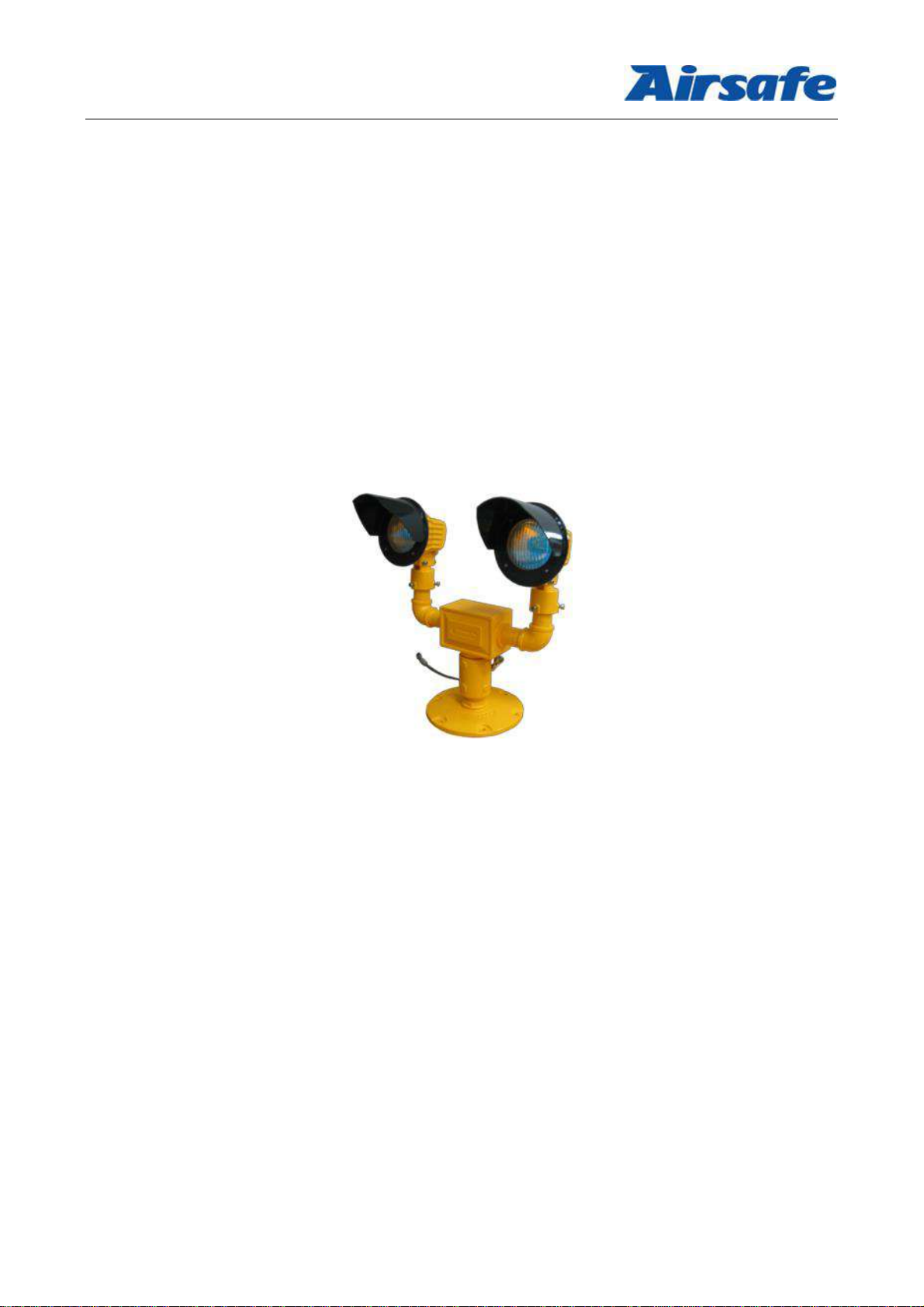
Advanced Airport Lighting System
- 1 -
Table of Content
Operation Manual ........................................................................................................................................ 1
Revision Description..................................................................................................................................... 2
1.0 Foreword................................................................................................................................................ 2
1.1 Illustrations and Meanings................................................................................................................... 3
1.2 Safety Rules and Notices..................................................................................................................... 4
1.3 Quality Assurance and Responsibility ................................................................................................... 5
2.0 Introduction............................................................................................................................................ 6
2.1 Technical Specifications...................................................................................................................... 6
2.2 Application Environment .................................................................................................................... 6
2.3 Technical Features ............................................................................................................................. 7
2.4 Technical Parameters.......................................................................................................................... 7
2.6 Structure........................................................................................................................................... 9
2.6.1 Boundary Dimension ................................................................................................................ 9
2.6.2 Main Components .................................................................................................................... 9
2.6.3 Structure Diagram of Light Body Assy.......................................................................................10
2.6.4 Structure Diagram of Holder Assy .............................................................................................10
3.0 Installation.............................................................................................................................................11
3.1 Installation Methods..........................................................................................................................11
3.2 Installation Steps...............................................................................................................................12
3.3 Horizontal and Vertical Beam Angle Adjustment of Lighting Fixtures......................................................13
3.3.1 Operating Units of Lighting Fixture Adjustment ..........................................................................13
3.3.2 Operating Unit of Calibrator Shown in Figure..............................................................................13
3.3.3 Calibrator Installation...............................................................................................................14
3.3.4 Adjustment of Horizontal Beam Angle:......................................................................................14
3.3.5 Adjustment of Vertical Beam Angle:..........................................................................................15
4.0 Lamp and Control..................................................................................................................................16
4.1 Light Wiring Schematic Diagram ........................................................................................................16
4.2 Light Intensity Adjustment and Control ...........................................................................................16
5.0 Maintenance of Lighting Fixtures............................................................................................................17
5.1 Replace Lamp...................................................................................................................................17
5.2 Daily Maintenance ............................................................................................................................18
5.3 List of Components and Ordering of Spare Articles and Accessories ........................................................19
5.4 Failure Countermeasures....................................................................................................................20
6.0 Packaging, Transportation and Storage...................................................................................................21
6.1 Packaging and Weight.....................................................................................................................21
6.2 Transportation Mode.......................................................................................................................21
6.3 Storage ...........................................................................................................................................21