Airspan ProST Manual

IP-based
Broadband Wireless Access (BWA) System
605-0000-706 Rev I
ProST
Hardware Installation Guide
SR 6.5
The Innovation Behind Broadband Wireless
Connecting the World

605-0000-706 ProST Installation User Guide-Rev I
ii
Table Of Contents
Introduction.......................................................................................................................1
Purpose..........................................................................................................................1
Targeted Audience ...........................................................................................................1
Referenced Documentation................................................................................................1
Conventions....................................................................................................................1
Warnings and Cautions........................................................................................................2
Human Exposure to Radio Frequencies................................................................................2
Radio Interference ...........................................................................................................2
Avoiding Radio Interference...............................................................................................2
Modifications ...................................................................................................................2
General ..........................................................................................................................2
Manufacturer's Disclaimer Statement ..................................................................................2
Declaration of Conformity ....................................................................................................4
European Community, Switzerland, Norway, Iceland, and Liechtenstein ...................................4
Declaration of Conformity with Regard to the R&TTE Directive 1999/5/EC.................................4
Fcc Interference Statement ..................................................................................................6
Federal Communication Commission Interference Statement..................................................6
Maximum Output TX Power ...............................................................................................7
System Overview................................................................................................................8
ProST Frequency Ranges...................................................................................................9
Main Features..................................................................................................................9
ProST-2 Frequency Ranges.............................................................................................. 10
Main Features................................................................................................................ 10
Architecture .................................................................................................................. 11
ProST Models.............................................................................................................. 12
ProST Block Diagram ................................................................................................... 13
ProST Protocol Stack ...................................................................................................... 13
Theory of Operation ....................................................................................................... 14
Physical Description .......................................................................................................... 15
ProST Physical Description............................................................................................... 15
Physical Dimensions..................................................................................................... 15
Port........................................................................................................................... 15
SDA-1 Physical Description.............................................................................................. 16
Physical Dimensions..................................................................................................... 17
Ports ......................................................................................................................... 17
LED........................................................................................................................... 17
SDA-4S Type II and SDA-4S/VL Type II (Optional).............................................................. 18

Table Of Contents
iii
Physical Dimensions..................................................................................................... 18
Ports ......................................................................................................................... 19
LEDs ......................................................................................................................... 19
SDA-4SDC Type II (Optional DC power supply) .................................................................. 20
Physical Dimensions..................................................................................................... 20
Ports ......................................................................................................................... 21
LEDs ......................................................................................................................... 21
Mounting the ProST........................................................................................................... 23
Mounting the ProST........................................................................................................ 23
Wall Mounting................................................................................................................ 24
Pole Mounting................................................................................................................ 26
SDA-4S ........................................................................................................................ 31
Desktop Mounting ....................................................................................................... 31
Wall Mounting............................................................................................................. 31
Network Cabling ............................................................................................................... 33
Connecting to IDU.......................................................................................................... 33
Using the SDA-1 Type II............................................................................................... 33
Using the SDA-4S Type II, SDA-4S/VL Type II or SDA-4S/DC Type II ................................. 34
Connecting to LAN Network ............................................................................................. 36
Using SDA-1 Type II .................................................................................................... 36
Using the SDA-4S Type II, SDA-4S/VL Type II or SDA-4S/DC Type II ................................. 38
Using SDA-MSG .......................................................................................................... 40
Using SDA-WiFi........................................................................................................... 41
Connecting to Power ......................................................................................................... 43
DC Power Source ........................................................................................................... 43
Connecting the SDA-4SDC Type II (Optional DC adapter)..................................................... 44
AC Power Source ........................................................................................................... 45
Using SDA-1 Type II .................................................................................................... 45
Using SDA-4S Type II and SDA-4S/VL Type II ................................................................. 47
Connecting Power Cable for SDA-4SDC ................................................................................ 49
Power Cable Connection.................................................................................................. 49
Housing the Connectors................................................................................................ 49
Connecting to the SDA-4SDC ........................................................................................ 49
Connecting Lightning and Surge Protector ............................................................................ 51
PolyPhaser Wiring Diagram.............................................................................................. 51
Lightning and Surge Protection Connection Scenarios ....................................................... 52
RSSI LED Plug Adapter ...................................................................................................... 56
Antenna Alignment using RSSI LED Plug Adapter................................................................ 56
LED Status.................................................................................................................... 57
Connecting External Antenna.............................................................................................. 59
605-0000-706 ProST Installation User Guide-Rev I
iv
Troubleshooting................................................................................................................ 61
Trademarks and Copyrights................................................................................................ 62
Contact Information.......................................................................................................... 63
Revisions......................................................................................................................... 64
Warnings......................................................................................................................... 65
1. Disclaimer................................................................................................................. 65
1.1 Safety Warnings....................................................................................................... 65
1.2 Important Warning Symbols....................................................................................... 65
1.3 Important Service Information.................................................................................... 66
1.4 UL Information......................................................................................................... 66
1.5 CE Notice ................................................................................................................ 66
1.6 European Community, Switzerland, Norway, Iceland, and Liechtenstein............................ 67
Declaration of Conformity with Regard to the R&TTE Directive 1999/5/EC............................ 67
1.7 CAUTION................................................................................................................. 68
1.8 Lightning Protection .................................................................................................. 68
Glossary.......................................................................................................................... 70
Index.............................................................................................................................. 73

1
INTRODUCTION
Thank you for purchasing Airspan's ProST wireless access device. The ProST customer premise
equipment (CPE) is part of Airspan's AS.MAX family of WiMAX-based products. ProST also has a
multimode model (ProST-2) based on the Rosedale chipset which supports both TDD and FDD.
Note: ProST-2 is presently available for frequencies, 3.4–3.6 and 3.6–3.8 only.
Note: For more information on the ProST-2 contact your supplier.
This section provides a preface by discussing the purpose, audience, organization, conventions, and
customer support of this guide.
Purpose
This guide provides step-by-step instructions for setting up and installing the ProST.
Targeted Audience
This guide is intended for the technician who is qualified and authorized to install the ProST.
Referenced Documentation
For a detailed description of the Web-based configuration tool, refer to the WiMAX Web-based
Management User's Guide.
Conventions
This guide uses the following typographical conventions:
Convention Meaning Example
Bold Command, menu, icon,
button, and field Click the Next button.
"To" in bold face and at the
beginning of a sentence Introduces a numbered
procedure To download a SW file:
Warning that provides
information that can prevent
and avoid bodily or
mechanical harm
--
Note that provides useful
information --

605-0000-706 ProST Installation User Guide-Rev I
2
WARNINGS AND CAUTIONS
Human Exposure to Radio Frequencies
The ProST should be installed and operated from a minimum distance of 36 cm to your body.
Radio Interference
This equipment generates, uses, and can radiate radio frequency energy and, if not installed and
used in accordance with the instructions, may cause harmful interference to radio communications.
However, there is no guarantee that interference will not occur in a particular installation. If this
equipment does cause harmful interference to radio or television reception, which can be
determined by turning the equipment on and off, the user is encouraged to try to correct the
interference by performing one or more of the following measures:
Reorientate or relocate the receiving antenna
Increase separation between the equipment and receiver
Connect the equipment to an outlet on a circuit different from that to which the receiver is
connected
Consult the dealer or an experienced radio/TV technician for help
Avoiding Radio Interference
This transmitter must not be co-located or operating in conjunction with any antenna or
transmitter.
Ensure a minimum of 1-meter separation between co-located ProST's.
When using an external antenna, the external antenna must not be co-located or operating
in conjunction with any other antenna or transmitter.
Modifications
Any changes and modifications to this device that are not expressly approved by Airspan may void
the user's authority to operate the equipment.
General
Only qualified personnel should be allowed to install, replace, and service the equipment.
The device cannot be sold retail, to the general public or by mail order. It must be sold to
dealers.
Installation must be controlled.
Installation must be performed by licensed professionals.
Installation requires special training.
The AS.MAX radios and antennas should be installed ONLY by experienced installation
professionals who are familiar with local building and safety codes and, wherever
applicable, are licensed by the appropriate government regulatory authorities. Failure to do
so may void Airspan's AS.MAX product warranty and may expose the end user or the
service provider to legal and financial liabilities. Airspan and its resellers or distributors are
not liable for injury, damage or violation of regulations associated with the installation of
outdoor units or antennas.
Do not mount outdoor radios and external antennas in weather that may increase risk of
electrocution such as rain or lightning.
To prevent ESD damage to devices, always wear an ESD wrist strap when handling these
devices or coming into contact with internal components.
Manufacturer's Disclaimer Statement

Warnings and Cautions
3
The information in this document is subject to change without notice and does not represent a
commitment on the part of the vendor. No warranty or representation, either expressed or implied,
is made with respect to the quality, accuracy or fitness for any particular purpose of this document.
The manufacturer reserves the right to make changes to the content of this document and/or the
products associated with it at any time without obligation to notify any person or organization of
such changes. In no event will the manufacturer be liable for direct, indirect, special, incidental or
consequential damages arising out of the use or inability to use this product or documentation, even
if advised of the possibility of such damages. This document contains materials protected by
copyright. All rights are reserved. No part of this manual may be reproduced or transmitted in any
form, by any means or for any purpose without expressed written consent of its authors. Product
names appearing in this document are mentioned for identification purchases only. All trademarks,
product names or brand names appearing in this document are registered property of their
respective owners.

605-0000-706 ProST Installation User Guide-Rev I
4
DECLARATION OF CONFORMITY
European Community, Switzerland, Norway, Iceland, and
Liechtenstein
Declaration of Conformity with Regard to the R&TTE Directive
1999/5/EC
English:
This equipment is in compliance with the essential requirements and other relevant
provisions of Directive 1999/5/EC.
Deutsch:
Dieses Gerät entspricht den grundlegenden Anforderungen und den weiteren
entsprecheneden Vorgaben der Richtlinie 1999/5/EU.
Dansk:
Dette udstyr er i overensstemmelse med de væsentlige krav og andre relevante
bestemmelser i Directiv 1999/5/EF.
Español:
Este equipo cumple con los requisitos esenciales asi como con otras disposiciones de la
Directive 1999/5/EC.
Greek:
ΜΕ ΤΗΝ ΠΑΡΟΥΣΑ Airspan ∆ΗΛΩΝΕΙ ΟΤΙ ΟΕΞΟΠΛΙΣΜΟΣ ΣΥΜΜΟΡΦΩΝΕΤΑΙ ΠΡΟΣ ΤΙΣ
ΟΥΣΙΩ∆ΕΙΣ ΑΠΑΙΤΗΣΕΙΣ ΚΑΙ ΤΙΣ ΛΟΙΠΕΣ ΣΧΕΤΙΚΕΣ ∆ΙΑΤΑΞΕΙΣ ΤΗΣ Ο∆ΗΓΙΑΣ 1999/5/ΕΚ.
Français:
Cet appareil est conforme aux exigencies essentialles et aux autres dispositions pertinantes
de la Directive 1999/5/EC.
Íslenska:
Þessi búnaður samrýmist lögboðnum kröfum og öðrum ákvæðum tilskipunar 1999/5/ESB.
Italiano:
Questo apparato é conforme ai requisiti essenziali ed agli altri principi sanciti dalla Direttiva
1999/5/EC.
Nederlands:
Deze apparatuur voldoet aan de belangrijkste eisen en andere voorzieningen van richtlijn
1999/5/EC.
Norsk:
Dette utstyret er i samsvar med de grunnleggende krav og andre relevante bestemmelser i
EU-directiv 1999/5/EC.
Português:
Este equipamento satisfaz os requisitos essenciais e outras provisões da Directiva
1999/5/EC.
Suomalainen:
Tämä laite täyttää direktiivin 1999/5/EY oleelliset vaatimukset ja on siinä asetettujen
muidenkin ehtojen mukainen.
Svenska:

Declaration of Conformity
5
Denna utrustning är i överensstämmelse med de väsentliga kraven och andra relevanta
bestämmelser i Direktiv 1999/5/EC.
The Declaration of Conformity related to this product can be obtained from

605-0000-706 ProST Installation User Guide-Rev I
6
FCC INTERFERENCE STATEMENT
Federal Communication Commission Interference Statement
This equipment has been tested and found to comply with the limits for a Class B digital device,
pursuant to Part 15 of the FCC Rules. These limits are designed to provide reasonable protection
against harmful interference in a residential installation. This equipment generates, uses and can
radiate radio frequency energy and, if not installed and used in accordance with the instructions,
may cause harmful interference to radio communications. However, there is no guarantee that
interference will not occur in a particular installation. If this equipment does cause harmful
interference to radio or television reception, which can be determined by turning the equipment off
and on, the user is encouraged to try to correct the interference by one of the following measures:
Reorient or relocate the receiving antenna.
Increase the separation between the equipment and receiver.
Connect the equipment into an outlet on a circuit different from that to which the receiver is
connected.
Consult the dealer or an experienced radio/TV technician for help.
This device complies with Part 15 of the FCC Rules. Operation is subject to the following two
conditions: (1) This device may not cause harmful interference, and (2) this device must accept any
interference received, including interference that may cause undesired operation.
FCC Caution: Any changes or modifications not expressly approved by the party responsible for
compliance could void the user's authority to operate this equipment.
IMPORTANT NOTE:
FCC Radiation Exposure Statement:
This equipment complies with FCC radiation exposure limits set forth for an uncontrolled
environment. This equipment should be installed and operated with minimum distance 36 cm
between the radiator & your body.
This transmitter must not be co-located or operating in conjunction with any other antenna or
transmitter.

Fcc Interference Statement
7
Maximum Output TX Power
CPE Maximum Output TX Power
Caution: Do not set maximum output TX power to higher than local regulations.

8
SYSTEM OVERVIEW
The ProST is an outdoor WiMAX-based customer premises equipment (CPE). The ProST, which uses
Intel Corporation’s Pro/Wireless 5116 broadband interface, connects IP-enabled devices directly to
WiMAX networks. Designed for the residential and small enterprise (SME) markets, the device
supports high-speed broadband Internet through a Fast Ethernet connection.
The ProST ensures high service availability at enhanced ranges, operating in both LOS and NLOS
propagation environments. ProST uses the OFDM signaling format, providing non line-of-sight
(NLOS) performance. ProST utilizes QAM, QPSK, and BPSK modulation technologies by modulating
transmitted signals and demodulating the received signals where the original digital message can be
recovered. The use of adaptive modulation allows ProST to optimize throughput, yielding higher
throughputs while also covering long distances.
ProST models support IP services at speeds of up to 37 Mbit/s over-the-air gross rates over channel
bandwidths of up to 10 MHz in both uplink and downlink. ProST is available in numerous ETSI
frequency bands, operating in FDD and TDD modes in numerous channels, see: ProST Frequency
Ranges and ProST-2 Frequency Ranges.
ProST is also available in a multi-mode model (ProST-2) based on the Intel ® Rosedale chipset
which supports both TDD and FDD.
Note: ProST-2 is presently available for frequencies, 3.4–3.6 and 3.6–3.8 only.
ProST can be deployed with a built-in, integral antenna or alternatively, with an external antenna to
provide better radio coverage. Requiring professional installation, the ProST is installed outdoors on
a pole or wall, enabling optimal positioning for best reception with the BS. Outdoor mounting of the
ProST is made possible due to ProST's built-in lightning surge protection feature (complying with
Surge Immunity standard EN 61000-4-5).
ProST is powered through the SDA-1 Type II (referred henceforth as SDA-1) adapter which
interfaces with the subscriber's LAN. ProST connects to the SDA-1's 100BaseT interface port by a
standard 100-meter CAT-5 cable. The SDA-1 also provides the ProST with 10 to 52 VDC power
supply. However, as an alternative to these adapters, Airspan offers three optional integrated LAN
switches:
SDA-4S Type II: A standard integrated LAN switch, providing four 10/100BaseT interfaces
with the subscriber’s computers. This model is ideal for SOHO implementation.
SDA-4S/VL Type II: Provides VLANs between ports and the ProST, ensuring privacy
between LAN users of the different ports. For example, all users connected to Port 1 do not
"see" users connected to Port 2. This model is ideal for multi-tenant (VLAN security)
implementation.
SDA-4S/DC Type II: integrated LAN switch, providing power and four 10/100BaseT
interfaces and especially designed for implementation where available power supply is DC
(10 to 52 VDC), e.g. from a solar panel. This model provides regulated –48 VDC power to
the BSR.
All SDA types work in VLAN Pass-through mode. Tagged and Untagged packets are forwarded
transparently by the SDA. The SDA has no VLAN ID configuration per port.
ProST can be managed by Airspan's Web-based management system using standard Web browsers
or alternatively, by an SNMP-based network management system (Netspan) using standard and
proprietary MIBs. In addition, external third-party management systems such as HP OpenView can
also manage the ProST using these MIBs.

System Overview
9
ProST Frequency Ranges
The table below lists the frequency range of ProST models currently available. This table will grow
as more models become available.
Frequency Band Channel Bandwidth
1.4265 – 1.524 in GHz TDD mode 1.75 MHz
3.5 MHz
5 MHz
3.3 – 3.5 GHz in TDD mode 1.75 MHz
2.75 MHz
3.5 MHz
5 MHz
3.4 – 3.6 GHz in FDD mode 1.75 MHz
3.5 MHz
3.6 – 3.8 GHz in TDD mode 1.75 MHz
3.5 MHz
5 MHz
4.9 – 5.0 GHz in TDD mode 2.5 MHz
5 MHz
10 MHz
5.15 – 5.35 GHz in TDD mode 2.5 MHz
5 MHz
10 MHz
5.47 – 5.725 GHz in TDD mode 2.5 MHz
5 MHz
10 MHz
5.725 – 5.875 GHz in TDD mode 2.5 MHz
5 MHz
10 MHz
5.850 – 5.950 GHz in TDD mode 2.5 MHz
5 MHz
10 MHz
Main Features
The ProST provides the following main features:
Full Outdoor Non-LOS Deployment: 256 OFDM
Based on the latest wireless technology WiMAX IEEE 802.16 standard
Integrated antenna gain of 15 dBi or 16 dBi (latest version)
Indoor Ethernet adapter (SDA-1 Type II):

605-0000-706 ProST Installation User Guide-Rev I
10
oproviding power and interface termination
oup to 100-m Category 5 cable between ProST and SDA-1
Indoor:
oSDA-4S Type II: small low cost IDU with built in LAN switch
oSDA-4SDC Type II: small low cost DC IDU with built in LAN Switch
oSDA-WiFi: enabling WiFi capability to the ProST CPE (optional)
oSDA-MSG (Multi-Service Gateway): enabling VoIP capability to the ProST CPE
(optional)
High throughput providing fast access at burst data rates up to 37 Mbps over-the-air (gross
rate) over up to a 10 MHz channel
Option of LAN switch with indoor adapter
Up to 4 ports with VLAN port switching
Supports multiple UL bursts per SS frame
Signal information can be obtained via Web Management Performance tool
Integral WiFi and LAN switch
Optional VoIP module -- available SDA-MSG, an extension module allowing you to add VoIP
functionality to your ProST unit(s).
Optional WiFi module -- available SDA-WiFi, an extension module allowing you to add WiFi
functionality to your ProST unit(s).
Note: Contact your Airspan representative for more information on the SDA-MSG VoIP
extension module or the SDA-WiFi extension module.
ProST-2 Frequency Ranges
The table below lists the frequency range of ProST-2, TDD/FDD Multimode models currently
available. This table will grow as more models become available.
Frequency Band Channel Bandwidth
3.4 – 3.6 GHz in TDD/FDD 50/100 mode 1.75 MHz
2.75 MHz
3.5 MHz
5 MHz
7 MHz
10 MHz
3.6 – 3.8 GHz in TDD/FDD 50/100 mode 1.75 MHz
2.75 MHz
3.5 MHz
5 MHz
7 MHz
10 MHz
Main Features
The ProST-2 provides the following main features:

System Overview
11
New CPE variants are equipped with Rosedale chipset enabling FDD/TDD multimode
operation, supporting 5 MHz and 7 MHz in both TDD and HFDD modes.
Full Outdoor Non-LOS Deployment: 256 OFDM
Based on the latest wireless technology WiMAX IEEE 802.16 standard
Integrated antenna gain of 16 dBi (latest version)
Indoor Ethernet adapter (SDA-1 Type II):
oproviding power and interface termination
oup to 100-m Category 5 cable between ProST and SDA-1
Indoor:
oSDA-4S Type II: small low cost IDU with built in LAN switch
oSDA-4SDC Type II: small low cost DC IDU with built in LAN Switch
oSDA-WiFi: enabling WiFi capability to the ProST CPE (optional)
oSDA-MSG (Multi-Service Gateway): enabling VoIP capability to the ProST CPE
(optional)
High throughput providing fast access at burst data rates up to 37 Mbps over-the-air (gross
rate) over up to a 10 MHz channel
Option of LAN switch with indoor adapter
Up to 4 ports with VLAN port switching
Supports multiple UL bursts per SS frame
Signal information can be obtained via Web Management Performance tool
Integral WiFi and LAN switch
Optional VoIP module -- available SDA-MSG, an extension module allowing you to add VoIP
functionality to your ProST unit(s).
Optional WiFi module -- available SDA-WiFi, an extension module allowing you to add WiFi
functionality to your ProST unit(s).
Note: Contact your Airspan representative for more information on the SDA-MSG VoIP
extension module or the SDA-WiFi extension module.
Architecture
The ProST installation consists of the following components:
Encased ProST outdoor unit (available in two variations)
SDA-1 indoor adapter or optional SDA-4S Type II, SDA-4S/VL Type II, or SDA-4S/DC Type
II
Third-party external antenna (optional deployment)
Note: The SDA-1 Type II adapter can also be implemented with other Airspan's ASWipLL
radios (i.e. BSR, PPR, and SPR). For further information regarding these products, please
contact your nearest Airspan dealer.
The figure below displays a typical architecture setup of the ProST with an integrated antenna.

605-0000-706 ProST Installation User Guide-Rev I
12
ProST Models
The ProST is available in the following variations, differing in antenna configuration:
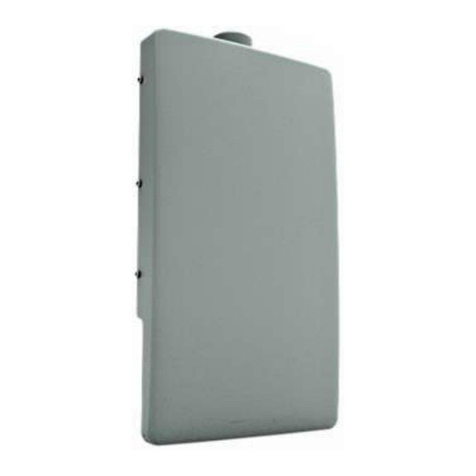
ProST with built-in (integrated), flat-panel antenna
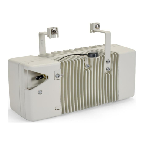
ProST with N-type connector for attaching third-party external antenna (i.e. no integrated
antenna)
The ProST model with the integrated antenna is shown below:
The ProST model with the N-type connector for connecting an external antenna is shown below:

System Overview
13
ProST Block Diagram
The figure below displays a block diagram of the ProST:
ProST Protocol Stack
The figure below displays a block diagram of the ProST's network architecture, designed as a
hierarchy of protocols (i.e. protocol stack) implemented in the communication network.

605-0000-706 ProST Installation User Guide-Rev I
14
Theory of Operation
For basic operation, the ProST requires no initial configuration--simply plug and play. Configuration
is automatically performed over the air by the BS. The ProST is preconfigured by the operator at the
BS (using Netspan) with service flow parameters such as the maximum information rate, the
committed information rate, the maximum latency. These configuration parameters are stored in
Netspan's database corresponding to the ProST's MAC address.
Before any communication between ProST and BS can occur, the ProST must be positioned in a
location that provides sufficient RF reception.
To join a network, the ProST needs to perform a few tasks. First, the "Network Entry" process
(defined in 802.16-2004) begins with the ProST scanning for a downlink (DL) signal from the base
station, and then synchronizing to the DL channel. Thereafter the ProST can start the process of
initial ranging, which alerts the BS to the presence of the ProST and establishment of management
connections to obtain basic and primary management connection IDs (CID) from the BS. After the
CIDs have been obtained, the ProST commences authorization and key exchange. In the final stage,
the ProST registers at the base station before obtaining the IP address, time of day and the
configuration file.
During Network entry, the ProST sends the BS its MAC address. The BS then accesses Netspan's
database (via SNMP) and checks whether the ProST's MAC address appears in the DB. If it locates
the MAC address, the BS retrieves all the ProST's configuration parameters (service flows) from the
DB and downloads them to the ProST device.

15
PHYSICAL DESCRIPTION
This section provides a description of the components of the ProST installation:
ProST radio (outdoor unit)
SDA-1 adapter (indoor unit -- switch and power interface)
SDA-4S Type II and SDA-4S/VL Type II adapters (optional)
SDA-4SDC Type II (indoor DC unit) (optional)
ProST Physical Description
The ProST is an encased outdoor radio providing access to communication ports on its bottom
panel. The ProST's back panel provides holes for ProST mounting.
This subsection provides the following ProST physical descriptions:
Dimensions
Ports
Physical Dimensions
The table below lists the physical dimensions of the ProST.
Parameter Value
Dimensions (H x W x D) 311 x 244 x 65.5 mm (12.24 x 9.6 x 2.57
inches)
Weight 1.94 kg (approximate)
Port
The ProST provides a 15-pin D-type port for interfacing with the SDA-1. For convenience, a
DB15-to-RJ45 adapter is supplied for attaching to the 15-pin D-type port to allow the use of RJ-
45 connectors for outdoor-to-indoor CAT 5 connectivity.
For ProST models implementing third-party external antennas, an N-type port is also provided
on the bottom panel.

605-0000-706 ProST Installation User Guide-Rev I
16
SDA-1 Physical Description
The SDA-1 is an integrated Ethernet and AC/DC power supply adapter that simply plugs into a
standard electrical wall outlet (110/240 VAC). The SDA-1 enables easy plug prong replacement to
suit geographical location of electrical outlet sockets (e.g. American vs. European).
The SDA-1 provides the ProST with the following interfaces:
10/100BaseT interface with subscriber's network/PC
10 to 52 VDC power supply
The SDA-1 physical description is shown in the figure below:
Other manuals for ProST
1
Table of contents
Other Airspan Wireless Access Point manuals

Airspan
Airspan EasyST Manual

Airspan
Airspan ASWipLL User manual

Airspan
Airspan ProST 4.9 Manual

Airspan
Airspan AS4000 Installation guide

Airspan
Airspan Mimosa A5x User manual

Airspan
Airspan AirVelocity 1500 User manual

Airspan
Airspan AS3010 Manual

Airspan
Airspan AIRSTRAND 2200 User manual

Airspan
Airspan AirSpeed 2900 User manual