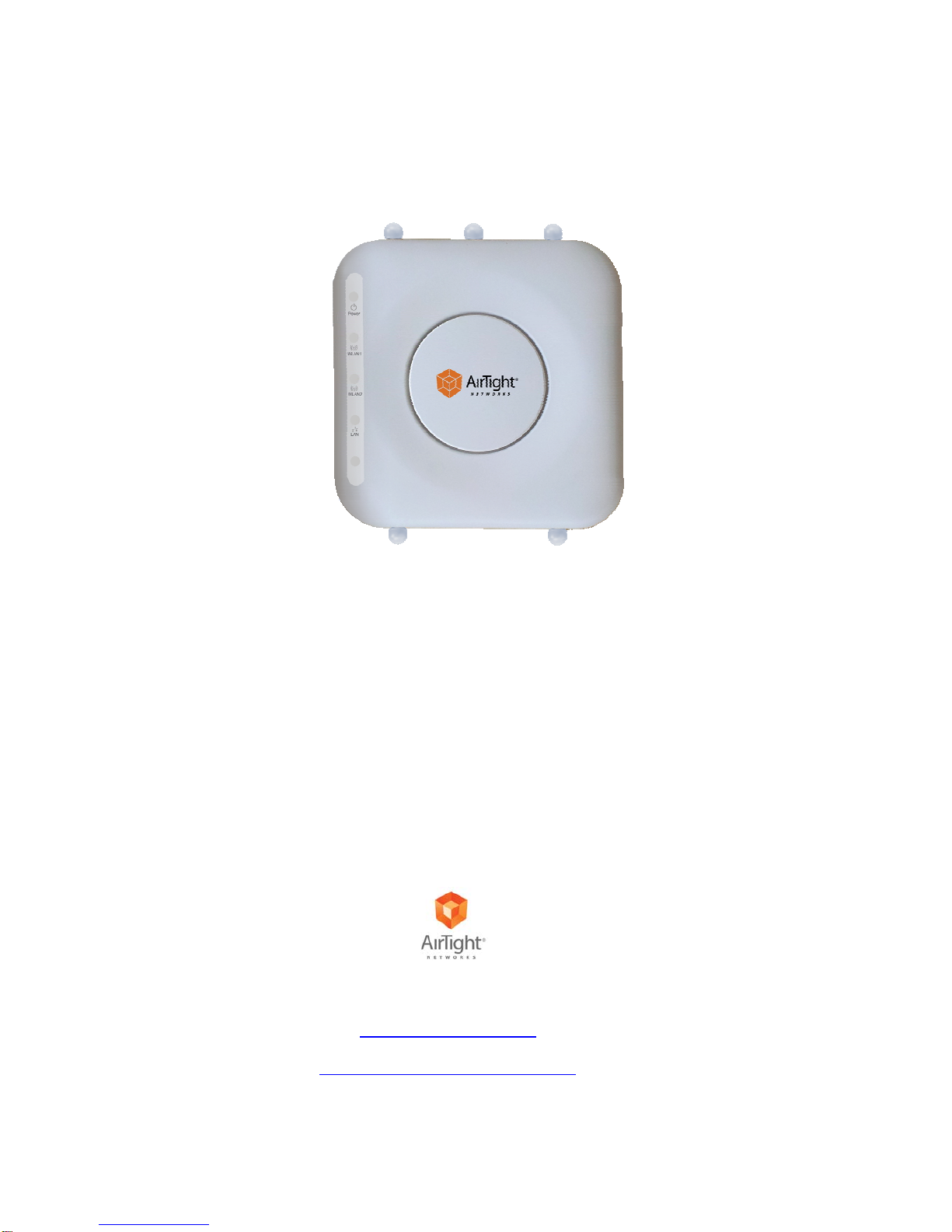
SS‐300‐AT‐C‐60InstallationGuide
ENDUSERLICENSEAGREEMENT
PleasereadtheEndUserLicenseAgreementbeforeinstallingtheSS‐300‐AT‐C‐60AccessPoint/Sensor.TheEndUserLicense
Agreementisavailableatthefollowinglocation‐.http://www.airtightnetworks.com/fileadmin/pdf/AirTight‐EULA.pdf.
InstallingtheSS‐300‐AT‐C‐60AccessPoint/SensorconstitutesyouracceptanceofthetermsandconditionsoftheEndUser
LicenseAgreement.
DISCLAIMER
THEINFORMATIONINTHISGUIDEISSUBJECTTOCHANGEWITHOUTANYPRIORNOTICE.
AIRTIGHT®NETWORKS,INC.ISNOTLIABLEFORANYSPECIAL,INCIDENTAL,INDIRECT,ORCONSEQUENTIAL
DAMAGESWHATSOEVER(INCLUDING,WITHOUTLIMITATION,DAMAGESFORLOSSOFBUSINESSPROFITS,
BUSINESSINTERRUPTION,LOSSOFBUSINESSINFORMATION,ORANYOTHERPECUNIARYLOSS)ARISINGOUTOF
THEUSEOFORINABILITYTOUSETHISPRODUCT.
THISPRODUCTHASTHECAPABILITYTOBLOCKWIRELESSTRANSMISSIONSFORTHEPURPOSEOFPROTECTING
YOURNETWORKFROMMALICIOUSWIRELESSACTIVITY.BASEDONTHEPOLICYSETTINGS,YOUHAVETHE
ABILITYTOSELECTWHICHWIRELESSTRANSMISSIONSAREBLOCKEDAND,THEREFORE,THECAPABILITYTO
BLOCKANEXTERNALWIRELESSTRANSMISSION.IFIMPROPERLYUSED,YOURUSAGEOFTHISPRODUCTMAY
VIOLATEUSFCCPART15ANDOTHERLAWS.BUYERACKNOWLEDGESTHELEGALRESTRICTIONSONUSAGEAND
UNDERSTANDSANDWILLCOMPLYWITHUSFCCRESTRICTIONSASWELLASOTHERGOVERNMENT
REGULATIONS.AIRTIGHTISNOTRESPONSIBLEFORANYWIRELESSINTERFERENCECAUSEDBYYOURUSEOF
THEPRODUCT.AIRTIGHTANDITSAUTHORIZEDRESELLERSORDISTRIBUTORSWILLASSUMENOLIABILITYFOR
ANYDAMAGEORVIOLATIONOFGOVERNMENTREGULATIONSARISINGFROMYOURUSAGEOFTHEPRODUCT,
EXPECTASEXPRESSLYDEFINEDINTHEINDEMNITYSECTIONOFTHISDOCUMENT.
LIMITATIONOFLIABILITY
AirTightwillnotbeliabletocustomeroranyotherpartyforanyindirect,incidental,special,consequential,exemplary,or
reliancedamagesarisingoutoforrelatedtotheuseofSpectraGuard®Enterpriseunderanylegaltheory,includingbutnot
limitedtolostprofits,lostdata,orbusinessinterruption,evenifAirTightknowsoforshouldhaveknownofthepossibilityof
suchdamages.Regardlessofthecauseofactionortheformofaction,AirTight’stotalcumulativeliabilityforactualdamages
arisingoutoforrelatedtotheuseofSpectraGuard®EnterprisewillnotexceedthepricepaidforSpectraGuard®Enterprise.
Copyright©2012AirTight®Networks,Inc.AllRightsReserved.
AirTight®Networks,TheAirTightlogo,andSpectraGuard®areregisteredtrademarksofAirTight®Networks.Allother
productsandservicesaretrademarks,registeredtrademarks,andservicemarksorregisteredservicemarksoftheirrespective
owners.
ThisproductcontainscomponentsfromOpenSourcesoftware.Thesecomponentsaregovernedbythetermsandconditions
oftheGNUPublicLicense.Toreadthesetermsandconditionsvisithttp://www.gnu.org/copyleft/gpl.html.
ThisproductisprotectedbyoneormoreofU.S.patentNos.7,002,943,7,154,874,7,216,365,7,333,800,7,333,481,7,339,914,
7,406,320,7,440,434,7,447,184,7,496,094,7,536,723,7,558,253,7,710,933,7,751,393,7,764,648,7,804,808,7,856,209,7,856,656,
7,970,894,7,971,253,8,032,939;AustralianpatentNo.200429804;U.K.patentNo.2410154;JapanpatentNo.4639195,andany
otherslistedatwww.airtightnetworks.com/patents.Morepatentspending.