manuals.online logo
Brands
  1. Home
  2. •
  3. Brands
  4. •
  5. CommScope
  6. •
  7. Wireless Access Point
  8. •
  9. CommScope RUCKUS T750 User manual

CommScope RUCKUS T750 User manual

Unleashed T750 Access Point
Quick Setup Guide
This Quick Setup Guide provides step-by-step instrucons on how to eld-
install the Ruckus Unleashed T750 access point (AP). For detailed
informaon on conguraon and management of the Unleashed T750,
refer to the Unleashed 200.9 Online Help, available at hps://
docs.ruckuswireless.com/unleashed/200.9/index.html.
WARNING! Only trained and qualied personnel should be allowed to
install, replace, or service this equipment.
WARNING! Installaon of this equipment must comply with local and
naonal electrical codes.
CAUTION! Make sure that you form a 80mm - 130mm (3”-5”) drip loop
in any cable that is aached to the AP or the building. This will prevent
water from running along the cable and entering the AP or the building
where the cable terminates.
CAUTION! Be sure that grounding is available and that it meets local
and naonal electrical codes. For addional lightning protecon, use
lightning rods and lightning arrestors.
CAUTION! Make sure that proper lightning surge protecon
precauons are taken according to local electrical code.
WARNING! Ruckus Wireless strongly recommends that you wear eye
protecon before mounng the T750 Omni.
This Guide in Other Languages
•请从以下网站获得该指南的简体中文版 hps://
support.ruckuswireless.com.
•Vous trouverez la version française de ce guide à l'adresse suivante
hps://support.ruckuswireless.com.
•このガイドの日本語版は hps://support.ruckuswireless.com でご覧
ください。
•이 가이드의 한국어 버전은 웹 사이트 (hps://
support.ruckuswireless.com) 에서 확인하시기 바랍니다.
•Veja a versão em português (Brasil) deste guia em hps://
support.ruckuswireless.com.
•Puede ver la versión en español (América Lana) de esta guía en
hps://support.ruckuswireless.com.
Required Hardware and Tools
•1/2” (13 mm) at-blade screwdriver or equivalent
•No. 2 Phillips screwdriver
•Small at-blade screwdriver
•Torque wrench or torque screwdriver with sockets
•Long-nose pliers
•Electrical wire stripping and terminal crimping pliers
•Pipe, pole or a sturdy at surface
•Electric drill with drill bits and customer-supplied wall anchors, at
washers, and hex nuts for at-surface mount
Package Contents
A complete T750 eld installaon package includes all of the items listed
below :
•T750 Access Point
•M25 data cable gland extender
•Three M25 data cable glands
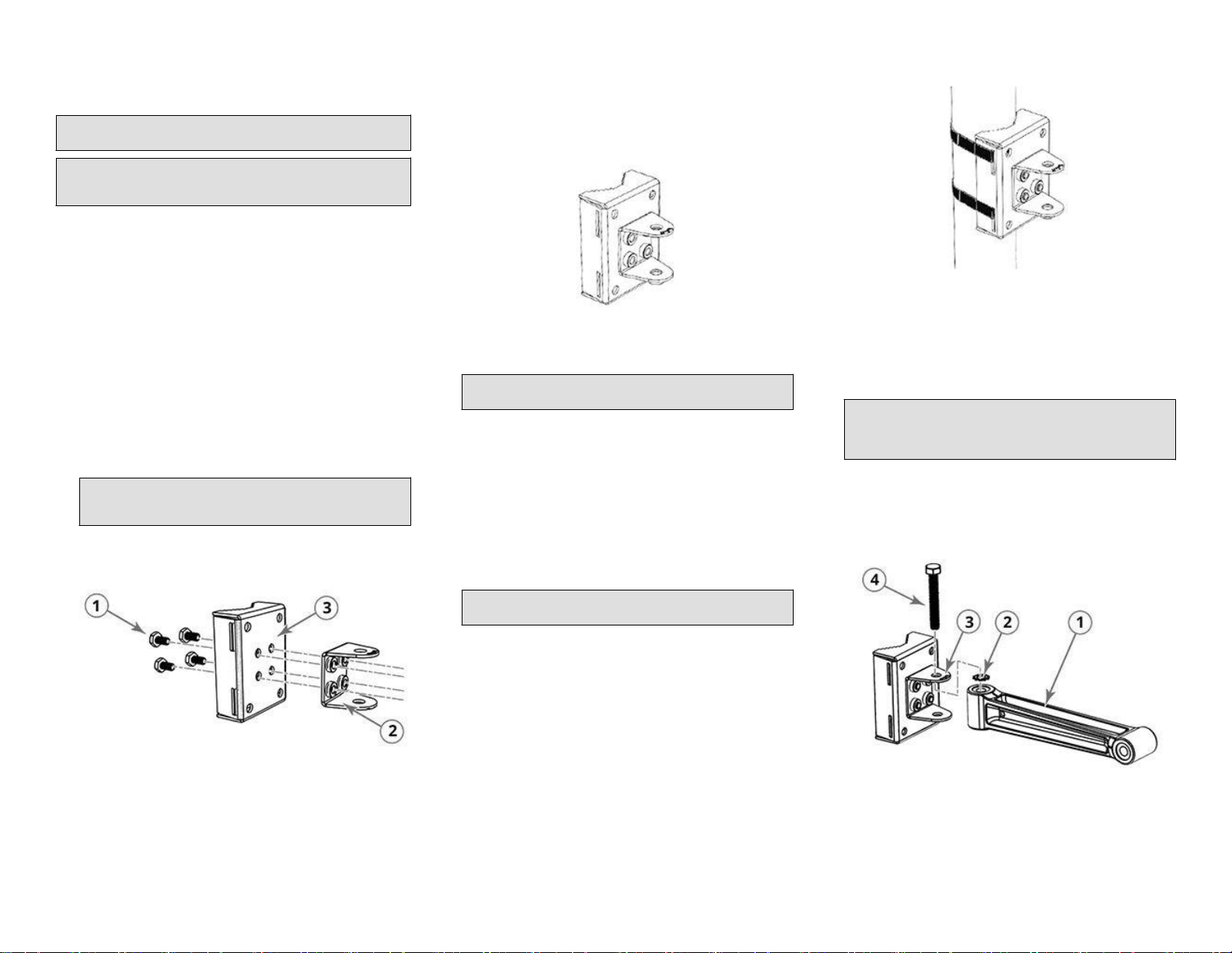
•Outdoor AP Mounng Bracket kit
•One ground wire with lug
•Cloud Management Statement
•Cable gland extender gasket
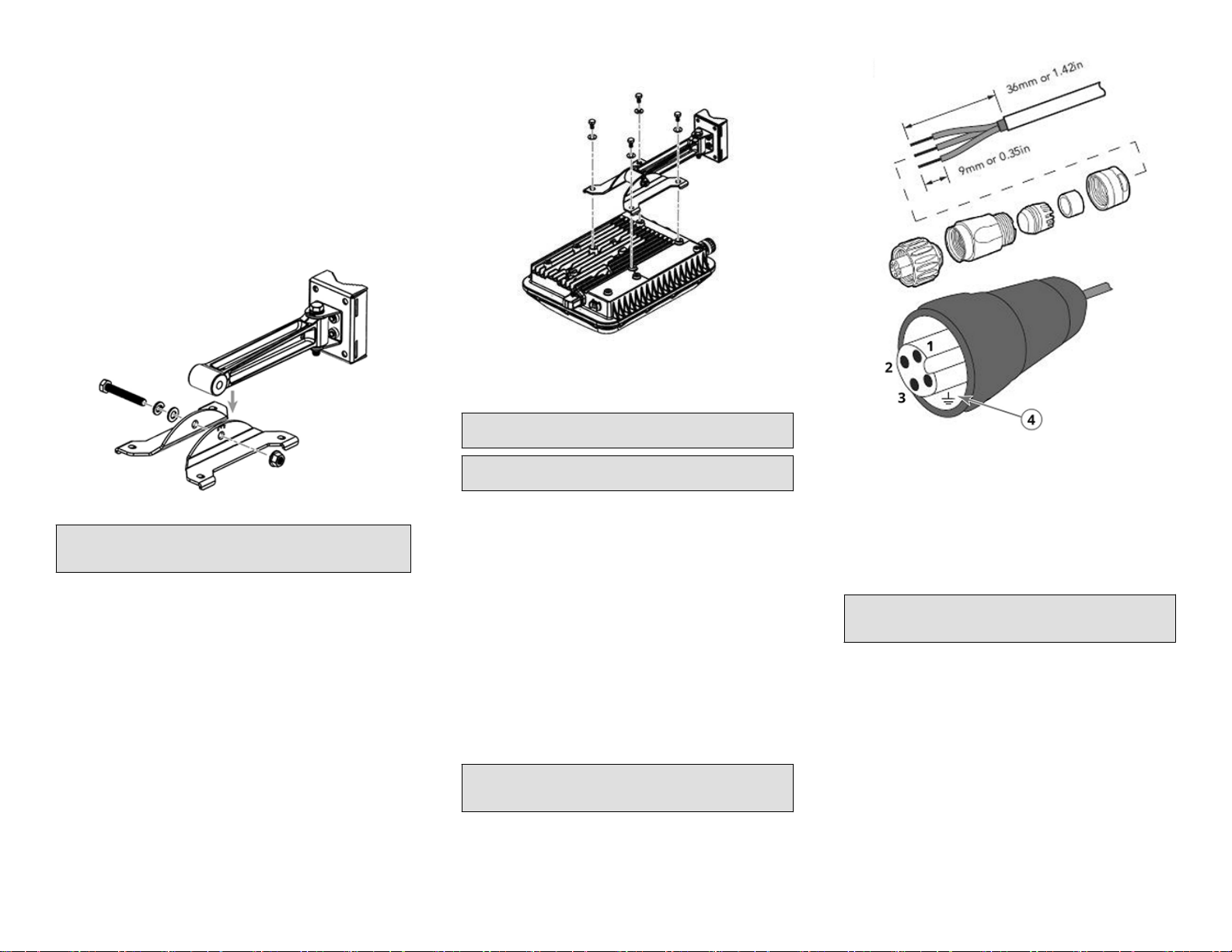
•AC Connector
•Zipcord cable gland grommet
•Four 1/2” (12.7 mm) wide adjustable clamps, 2.5” (63.5 mm) diameter,
for main mounng bracket on smaller poles
•Safety cable kit
•Service Level Agreement/Limited Warranty Statement
•Declaraon of Conformity
•Regulatory Statement
•Ruckus Wireless AP Geng Started Guide
•This Quick Setup Guide
Unleashed Network Conguraon
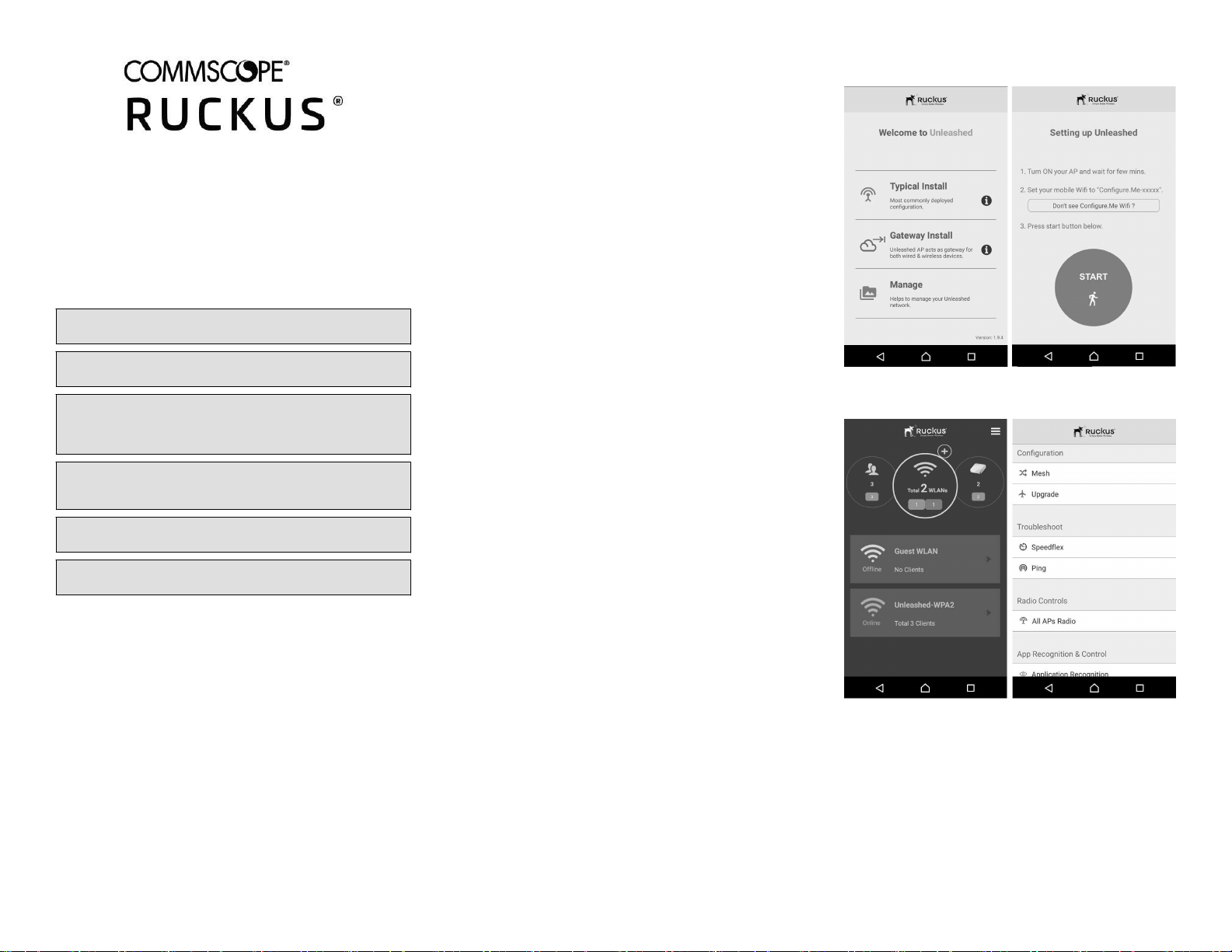
Setup Using the Unleashed Mobile App
To perform setup using the Unleashed Mobile App, download the iOS or
Android app from the app store.
1. As soon as the Unleashed AP is powered on and connected to the
local network, it boots up and begins broadcasng a temporary
unencrypted WLAN named “Congure.Me-[xxxxxx]” from both radios.
2. Using your client’s Wi-Fi connecon sengs, select and associate to
the “Congure.Me-[xxxxxx]” WLAN.
3. Launch the app, and follow the on-screen instrucons to congure
your Unleashed network(s).
FIGURE 1 Unleashed Mobile App for iOS and Android
FIGURE 2 Conguring Unleashed from the Mobile App
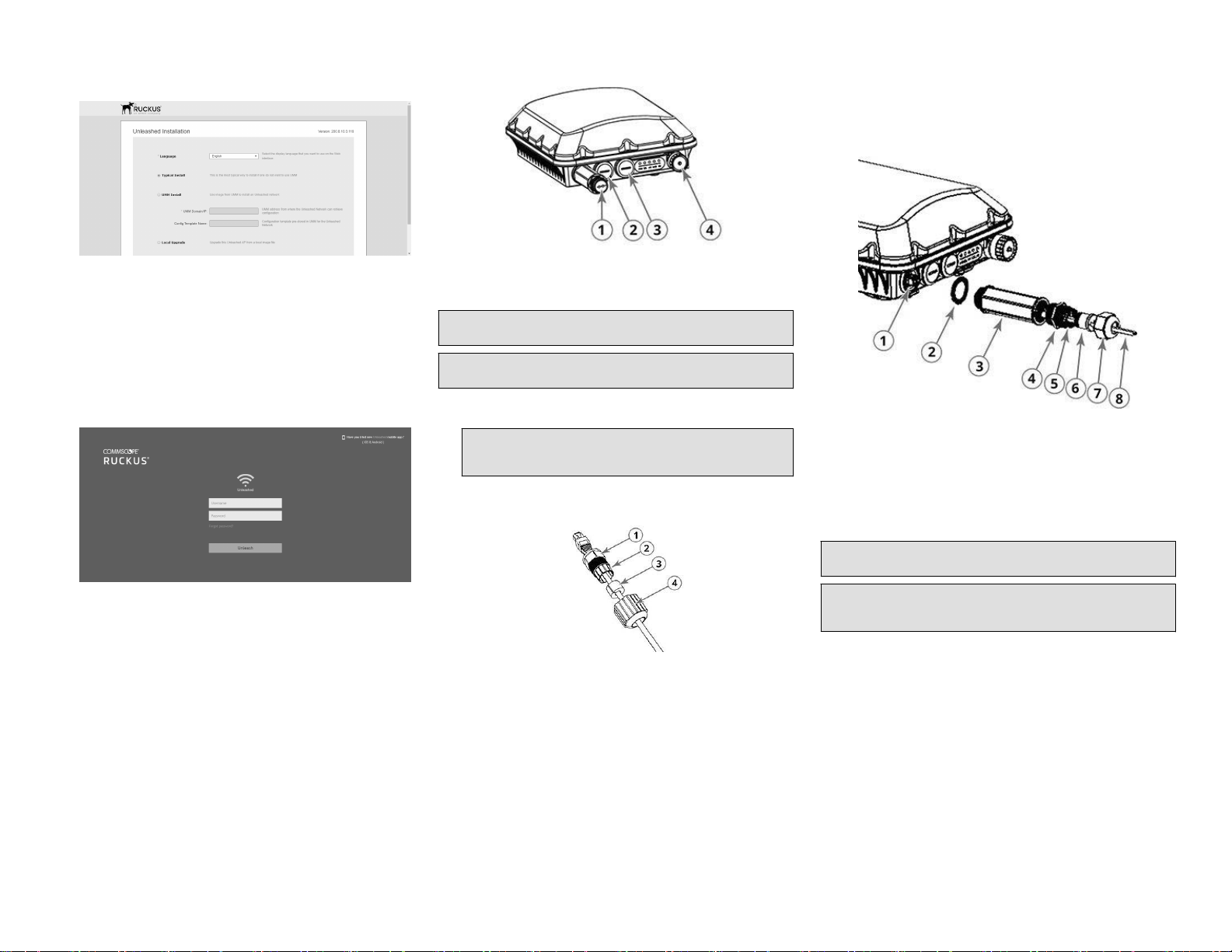
Setup Using a Web Browser
1. As soon as the Unleashed AP is powered on and connected to the
local network, it boots up and begins broadcasng a temporary
unencrypted WLAN named “Congure.Me-[xxxxxx]” from both radios.
2. Using your client’s Wi-Fi connecon sengs, select and associate to
the “Congure.Me-[xxxxxx]” WLAN.
3. Launch a web browser and enter the following into the browser’s URL
bar: unleashed.ruckuswireless.com, and press Enter.
4. You will be redirected to the Setup Wizard. Complete the steps in the
Setup Wizard and click Finish.
Copyright © 2020 CommScope, Inc. All rights reserved. Page 1 of 4
Published July 2020, Part Number 800-72627-001 Rev A
FIGURE 3 Complete the Setup Wizard to set up your Unleashed
network
5. Once the Setup Wizard is nished, a “Conguring system sengs and
reboong” progress screen appears. Wait unl the process is
complete.
6. Connect to the WLAN that you congured in the Setup Wizard, and
click OK to reconnect. You will be redirected to the Unleashed login
screen.
7. Enter your Admin Name and Password to login.
FIGURE 4 The Login page
8. Upon successful login you will be presented with the Unleashed
Dashboard, which displays an overview of your Ruckus Unleashed
network.
Mounng Instrucons
Connecng and Sealing the RJ-45 Cables
The T750 may use zero, or one or two RJ-45 cables, one for Ethernet when
congured as a Root AP (RAP), and another when the T750 is supplying
PoE out to a peripheral device, such as a small cell or micro cell radio.
When the T750 uses RJ-45 cables, connect and seal the cables using the
M25 data cable glands as shown in Figure 2.
FIGURE 5 T750 AP PoE IN and PoE OUT ports
1. SFP port
2. PoE IN
3. PoE OUT
4. AC port
WARNING! Do not use any PoE injector not tested and approved by
Ruckus Wireless to power the T750 Access Point.
WARNING! Do not plug PoE IN power into the PoE OUT port. See Figure
1.
1. Feed the end of the cable through the gland dome, rubber grommet,
clamping ring assembly and cable gland base, as shown in Figure 2.
NOTE: Do not seat the clamping ring and rubber grommet into the
cable gland base unl the cable gland base has been torqued to
specicaons.
FIGURE 6 RJ-45 Cable and Cable Gland Assembly
1. SFP Port
2. Clamping ring
3. Rubber grommet
4. Gland dome
2. Use a wide at-blade screwdriver to remove the required (PoE OUT or
PoE IN) blanking cap from the T750.
3. Connect the cable to the Ethernet port in the AP.
4. Tighten the cable gland base to 7 N.m (62 in-lbs).
5. Wrap the clamping ring assembly around the rubber grommet. Make
sure that the clamping ring assembly fully encloses the rubber
grommet.
6. Seat the clamping ring assembly and rubber grommet in the cable
gland base.
7. Hand-ghten the gland dome.
Connecng the SFP Opc Module Using a Single
Diameter Cable
You can use a single diameter cable to connect to the SFP opc module.
FIGURE 7 SFP module cable gland assembly
1. SFP transceiver
2. Cable gland gasket
3. Cable gland extender
4. Cable gland base
5. Clamping ring
6. Cable gland grommet / zipcord
cable gland grommet
7. Gland dome
8. Fibre cable
WARNING! The ber cable is extremely fragile and must be handled
with care.
NOTE: Do not insert the cable gland base/grommet/dome into the
extender unl the extender has been ghtened. Step 5 must be
performed before Step 6, else the ber cable will twist.
1. Place the cable gland base to the cable gland extender and ghten
the cable gland base to 7 N.m (62 in-lbs).
2. Fix the Cable gland extender gasket to the cable gland extender.
3. Feed the ber cable through the gland dome, cable gland grommet,
clamping ring, cable gland base, cable gland extender, and cable gland
gasket as shown in Figure 3.
4. Connect the ber cable to the SFP transceiver in the AP.
5. Tighten the cable gland extender to 7 N.m (62 in-lbs).
6. Insert the cable gland grommet into the clamping ring with the ber
cable in the center.
7. Insert the clamping ring into the cable gland base.
8. Tighten the cable gland dome to 7 in-lbs.
The SFP module is hot-swappable and can be removed with ngers or
simple tools.
Copyright © 2020 CommScope, Inc. All rights reserved. Page 2 of 4
Published July 2020, Part Number 800-72627-001 Rev A
Connecng the SFP Opc Module Using a Zipcord
Cable
You can use a zipcord cable to connect to the SFP opc module.
WARNING! The zipcord ber cable is extremely fragile and must be
handled with care.
NOTE: Do not insert the cable gland base/grommet/dome into the
extender unl the extender has been ghtened. Step 5 must be
performed before Step 6, else the ber cable will twist.
1. Place the cable gland base to the cable gland extender and ghten
the cable gland base to 7 N.m (62 in-lbs).
2. Fix the Cable gland extender gasket to the cable gland extender.
3. Feed the zipcord ber cable through the gland dome, zipcord cable
gland grommet, clamping ring, cable gland base, cable gland
extender, and cable gland gasket as shown in Figure 3.
4. Connect the zipcord ber cable to the SFP transceiver in the AP.
5. Tighten the cable gland extender to 7 N.m (62 in-lbs).
6. Insert the zipcord cable gland grommet into the clamping ring with
the zipcord ber cable in the two holes.
7. Insert the clamping ring into the cable gland base.
8. Tighten the cable gland dome to 7 in-lbs.
The SFP module is hot-swappable and can be removed with ngers or
simple tools.
Aaching the U-Joint Bracket to the Mounng Bracket
1. Posion the U-joint bracket on the mounng bracket.
NOTE: Mount the U-joint bracket in any direcon on the mounng
bracket, preferably to allow AP azimuth adjustments. Then the AP
bracket allows AP elevaon adjustments.
FIGURE 8 U-joint bracket aached horizontally to the mounng
bracket
1. Bolts
2. U-joint bracket
3. Mounng bracket
2. Use four 1/4 - 28 bolt and washer sets (1) to mount the U-joint
bracket (2) to the mounng bracket (3). Tighten the bolts to 9.5 N.m
(84 in-lbs).
3. Connue with Aaching the Mounng Bracket to a Flat Surface on
page 3.
Aaching the Mounng Bracket to a Flat Surface
1. Place the mounng bracket at the locaon on the at surface where
you want to mount the AP. Use the holes on the mounng bracket as
a template to mark the locaons of the mounng holes.
FIGURE 9 Mounng bracket at surface holes
2. Remove the mounng bracket from the at surface.
3. Drill holes required for the mounng hardware.
NOTE: The hardware required for mounng to a wall are not
included in the mounng kit.
4. Aach the mounng bracket to the at surface using the mounng
hardware.
5. Using the mounng hardware instrucons, ghten the hardware to
secure the mounng bracket.
6. Connue with Aaching the Mounng Bracket to a Pole on page 3.
Aaching the Mounng Bracket to a Pole
1. Insert the open end of one steel clamp into the upper two slots on
the mounng bracket.
2. Take the other steel clamp and insert it into the lower two slots on
the mounng bracket.
NOTE: The clamps can be daisy-chained together to accommodate
larger poles.
3. Use the clamps to aach the mounng bracket to the pole. Tighten
the clamps to 3 N.m (27 in-lbs) or per manufacturer’s specicaons.
FIGURE 10 Aaching the mounng bracket to a vercal pole
4. Connue with Mounng the Linkage Bracket to the U-Joint Bracket on
page 3.
Mounng the Linkage Bracket to the U-Joint Bracket
1. The linkage bracket aaches to the U-joint bracket using an M8 bolt
and washer set. The linkage bracket is symmetrical, and either end
can be aached to the U-joint bracket.
NOTE: Make sure that linkage bracket is installed with its serrated
external-tooth lock washer on the inside of the U-joint bracket
anges. This ensures that the azimuth adjustment does not
change.
2. Loosely assemble the linkage bracket (1), the U-joint bracket (3), one
serrated external-tooth lock washer (2), and one M8 bolt and washer
set (4).
FIGURE 11 Aaching the linkage bracket to the U-joint bracket
1. Linkage bracket
2. U-joint braket
3. External-tooth lock
washer
4. M8 bolt
3. Set the azimuth required by the AP.
4. Tighten the M8 bolt to 13.6 N.m (120 in-lbs).
Copyright © 2020 CommScope, Inc. All rights reserved. Page 3 of 4
Published July 2020, Part Number 800-72627-001 Rev A
5. Connue with Aaching the AP Bracket to the Linkage Bracket on
page 4.
Aaching the AP Bracket to the Linkage Bracket
Aach the AP bracket to the linkage bracket using the included bolt, lock
washer, at washer, serrated external-tooth washer and nut shown in the
illustraon below.
The linkage bracket is symmetrical, and either end can be aached to the
AP bracket.
Loosely assemble the AP bracket to the linkage bracket using the M8 bolt,
washer and nut set.
FIGURE 12 Aach the linkage bracket to the AP bracket
NOTE: Make sure that the linkage bracket is installed with its serrated
external-tooth lock washer on the inside of the AP bracket anges. This
ensures that the elevaon adjustment does not change.
Aaching the AP Bracket to the Access Point
1. Place the AP bracket onto the back side of the AP so that the four
larger screw holes on the bracket align with the four screw holes on
the AP.
FIGURE 13 Aaching the AP bracket to the AP
2. Use four 0.5-inch x 0.250-28 hex bolts with split lock and at washer
sets to mount the AP bracket to the AP. Tighten the bolts to 2.5-3.0
N.m (22-27 in-lbs).
CAUTION! Make sure that the screws are no longer than 0.5 inch.
If a screw is longer than 0.5 inch, it can damage the AP chassis.
NOTE: This kit may include extra screws, nuts and washers. You
may use the extras where required.
3. Connue with Set the Elevaon and Tighten the Elevaon Bolt on
page 4.
Set the Elevaon and Tighten the Elevaon Bolt
1. Set the elevaon required by the AP.
2. Tighten the M8 bolt to 13.6 N.m (120 in-lbs).
3. Connue with Powering the AP with AC on page 4.
Powering the AP with AC
1. Separate the AC cable connector parts by unscrewing the boot from
the cable gland and the cable gland from the connector housing..
2. Feed the end of the AC cable through the boot and cable gland.
3. Strip the AC cable as shown.
4. Insert the stripped part of the conductors into the appropriate
terminals on the connector housing. The conductors are color coded
and must be connected to the appropriate terminals as shown in
gure below.
NOTE: The color coding of wire conductors varies by region. Before
compleng this step, check your local wiring standards for
guidance.
FIGURE 14 Assembling the AC power connector
Wire Stripping (Not Actual Size)
1. (Neutral/Return): White
or Gray (US), Blue (EU)
2. (Line/Hot): Black (US),
Brown (EU)
3. (not used)
4. (Earth Ground): Green
(US), Green/Yellow (EU)
5. Using a small screwdriver, ghten the small screws around the
connector housing to x the connector pins into the terminals.
6. Mate the cable gland with the connector housing, and then hand-
ghten.
NOTE: Two dierent-sized grommets are supplied in the AC
connector assembly kit. Use the grommet that is appropriate to
the diameter of the AC cable that you are using.
7. Mate the boot with the cable gland, and then hand-ghten to seal.
8. Connect the AC cord connector that you have assembled to the AC
power socket on the AP.
9. Connect the AC cord to an AC power source.
© 2020 CommScope, Inc. All rights reserved.
ARRIS, the ARRIS logo, COMMSCOPE, RUCKUS, RUCKUS WIRELESS, the Ruckus
logo, and the Big Dog design are trademarks of CommScope, Inc. and/or its
aliates. Wi-Fi Alliance, Wi-Fi, the Wi-Fi logo, Wi-Fi Cered, the Wi-Fi
CERTIFIED logo, Wi-Fi Protected Access, the Wi-Fi Protected Setup logo, Wi-Fi
Protected Setup, Wi-Fi Mulmedia and WPA2 and WMM are trademarks or
registered trademarks of Wi-Fi Alliance. All other trademarks are the property of
their respecve owners.
Copyright © 2020 CommScope, Inc. All rights reserved. Page 4 of 4
Published July 2020, Part Number 800-72627-001 Rev A

Other CommScope Wireless Access Point manuals

CommScope RUCKUS R760 User manual

CommScope

CommScope RUCKUS R760 User manual

CommScope RUCKUS Unleashed R650 User manual

CommScope

CommScope RUCKUS Unleashed R650 User manual

CommScope RUCKUS T811-CM User manual

CommScope

CommScope RUCKUS T811-CM User manual

CommScope Ruckus Unleashed R650p User manual

CommScope

CommScope Ruckus Unleashed R650p User manual

CommScope ERA CAP L2 18/21/ 23T/26 F-DC User manual

CommScope

CommScope ERA CAP L2 18/21/ 23T/26 F-DC User manual

CommScope RUCKUS E510 User manual

CommScope

CommScope RUCKUS E510 User manual

CommScope RUCKUS R550p User manual

CommScope

CommScope RUCKUS R550p User manual

CommScope RUCKUS T350se User manual

CommScope

CommScope RUCKUS T350se User manual

CommScope SYSTIMAX InstaPATCH 360 Guide

CommScope

CommScope SYSTIMAX InstaPATCH 360 Guide

CommScope RUCKUS T350c User manual

CommScope

CommScope RUCKUS T350c User manual

CommScope RUCKUS Unleashed H550 User manual

CommScope

CommScope RUCKUS Unleashed H550 User manual

CommScope RUCKUS H350 User manual

CommScope

CommScope RUCKUS H350 User manual

CommScope T750SE User manual

CommScope

CommScope T750SE User manual

CommScope OneCell RP5000 Series Manual

CommScope

CommScope OneCell RP5000 Series Manual

CommScope Era M0201AKB_uc User manual

CommScope

CommScope Era M0201AKB_uc User manual

CommScope Era User manual

CommScope

CommScope Era User manual

CommScope RUCKUS H550 User manual

CommScope

CommScope RUCKUS H550 User manual

CommScope RUCKUS R550 User manual

CommScope

CommScope RUCKUS R550 User manual

CommScope ERA CAP M2 User manual

CommScope

CommScope ERA CAP M2 User manual

CommScope RUCKUS Unleashed T350SE User manual

CommScope

CommScope RUCKUS Unleashed T350SE User manual

CommScope ION E Series User manual

CommScope

CommScope ION E Series User manual

CommScope RUCKUS R850 User manual

CommScope

CommScope RUCKUS R850 User manual

CommScope RUCKUS R350 User manual

CommScope

CommScope RUCKUS R350 User manual

CommScope RUCKUS User manual

CommScope

CommScope RUCKUS User manual

Popular Wireless Access Point manuals by other brands

ALTAI A3 Series Configuration guide

ALTAI

ALTAI A3 Series Configuration guide

Ubiquiti airFiber AF-24-US quick start guide

Ubiquiti

Ubiquiti airFiber AF-24-US quick start guide

TP-Link 54Mbps Wireless Access Point TL-WA501G user guide

TP-Link

TP-Link 54Mbps Wireless Access Point TL-WA501G user guide

Allnet ALL0258 user manual

Allnet

Allnet ALL0258 user manual

Cisco Aironet 3600 Series Getting started guide

Cisco

Cisco Aironet 3600 Series Getting started guide

Hawking NK340W Specifications

Hawking

Hawking NK340W Specifications

WEISS MAN301R user manual

WEISS

WEISS MAN301R user manual

D-Link AirPremier N DAP-2310 Quick installation guide

D-Link

D-Link AirPremier N DAP-2310 Quick installation guide

Edge-Core ECW7220-L quick start guide

Edge-Core

Edge-Core ECW7220-L quick start guide

Acksys RuggedAir1000 Quick installation guide

Acksys

Acksys RuggedAir1000 Quick installation guide

Radwin WinLink 1000 Installation and operation manual

Radwin

Radwin WinLink 1000 Installation and operation manual

EnGenius ENH500 Technical specifications

EnGenius

EnGenius ENH500 Technical specifications

Baicells Nova442i installation guide

Baicells

Baicells Nova442i installation guide

Planet WDAP-C7200AC user manual

Planet

Planet WDAP-C7200AC user manual

NetComm NP730 user guide

NetComm

NetComm NP730 user guide

Zcom AC-1028 quick start guide

Zcom

Zcom AC-1028 quick start guide

US Robotics USR5450 installation guide

US Robotics

US Robotics USR5450 installation guide

Anybus AWB4003-B user manual

Anybus

Anybus AWB4003-B user manual

manuals.online logo
manuals.online logoBrands
  • About & Mission
  • Contact us
  • Privacy Policy
  • Terms and Conditions

Copyright 2025 Manuals.Online. All Rights Reserved.