9
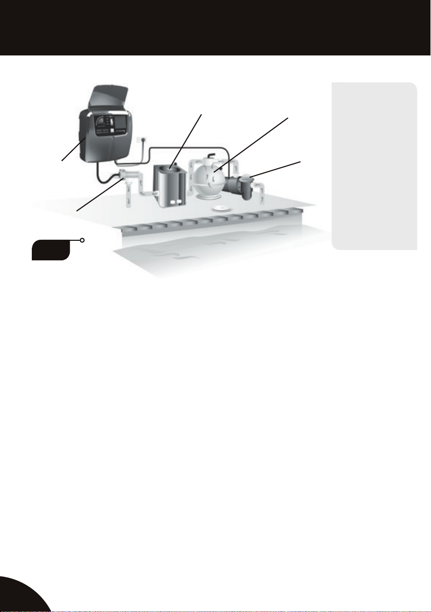
PUMP OUTPUT SOCKET
A 240 volt pump output power socket is supplied and located on the right hand underside of
the power supply. Your pool pump power supply lead should be plugged into this socket so that
when the time clock switches at your designated times both the salt water chlorinator and pool
pump will activate in unison.
Do not attempt to operate the chlorinator power supply with the pool pump lead disconnected
as this will lead to a gas build-up inside the cell housing causing it to overheat resulting in
damage to your chlorinator equipment that is not covered by warranty. In extreme cases gas
build-up may also cause the cell housing to rupture and explode, as it is not built to withstand
this type of pressure, possibly resulting in personal injury.
The pump socket is designed to operate a single pool pump of maximum 1.5 hp (horse power)
only. Do not attempt to operate any equipment other than your pool pump from this socket as
damage might occur to the power supply unit that is not covered under warranty.
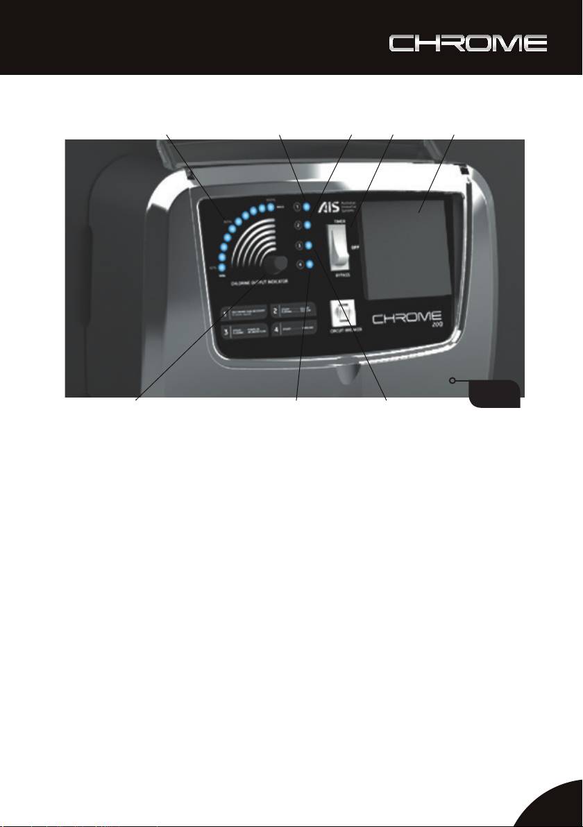
WARNING INDICATOR LIGHTS
(FIG. 1, ITEMS 1, 2, 3 & 4)
There are four (4) warning indicator lights located on the front of your chlorinator. These
advise at a glance the status of the chlorinator power supply and, when illuminated they
indicate and advise about the situation that the chlorinator’s electronic monitoring system
has detected. The lights and their functions are listed below.
1. ORANGE LIGHT: SALT HIGHER THAN NECESSARY
no action required
When illuminated this indicates that you have exceeded recommended salt levels. As long
as this is not causing your chlorinator to overload no further action or reduction of salt
concentration is required at this point. No further salt should be added if this light is illuminated.
2. ORANGE LIGHT: STEADY CELL OFF
chlorinator on standby
FLASHING SALT LOW
add salt and/or clean cell
STEADY – When illuminated in a STEADY continuous light your chlorine production has been
switched o by turning the chlorine controller anti clockwise and your chlorinator power supply
is now in a standby mode. Turn the chlorine controller clockwise to resume normal operation.
FLASHING – If the light is illuminated and FLASHING the monitoring system has detected low
salt levels and this will need to be adjusted for the chlorinator to operate at maximum capacity.
This light will also ash if the cell has reached a point where its output is below the normal
operating output. Please refer to the section detailing the addition of salt to your pool.