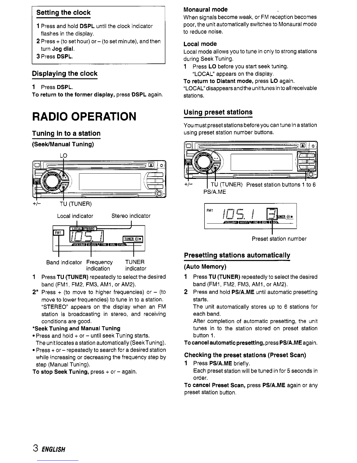
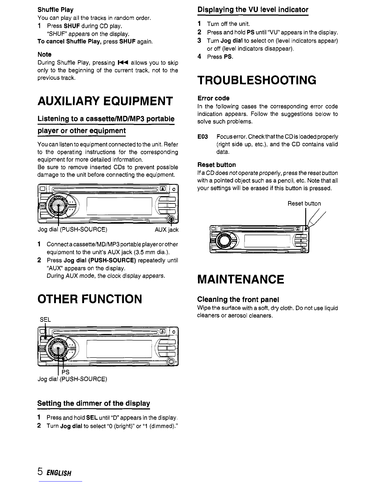
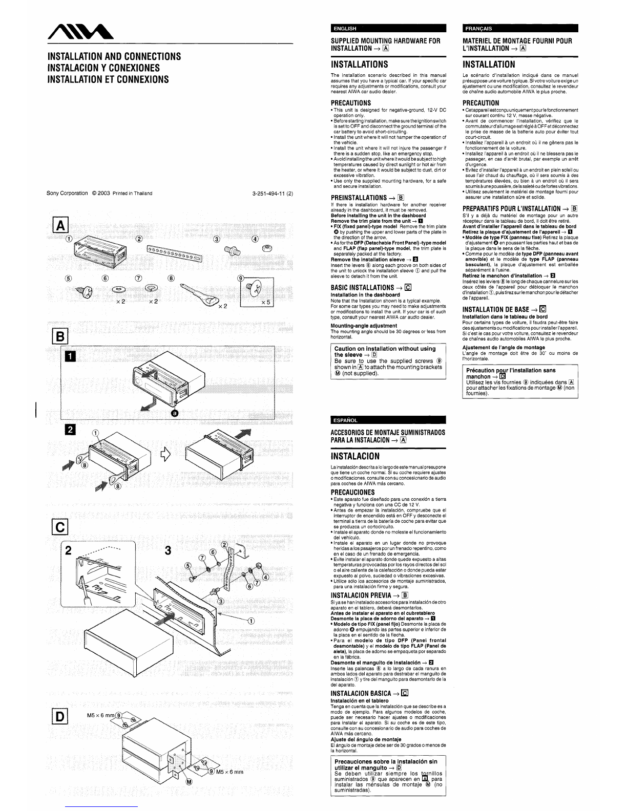
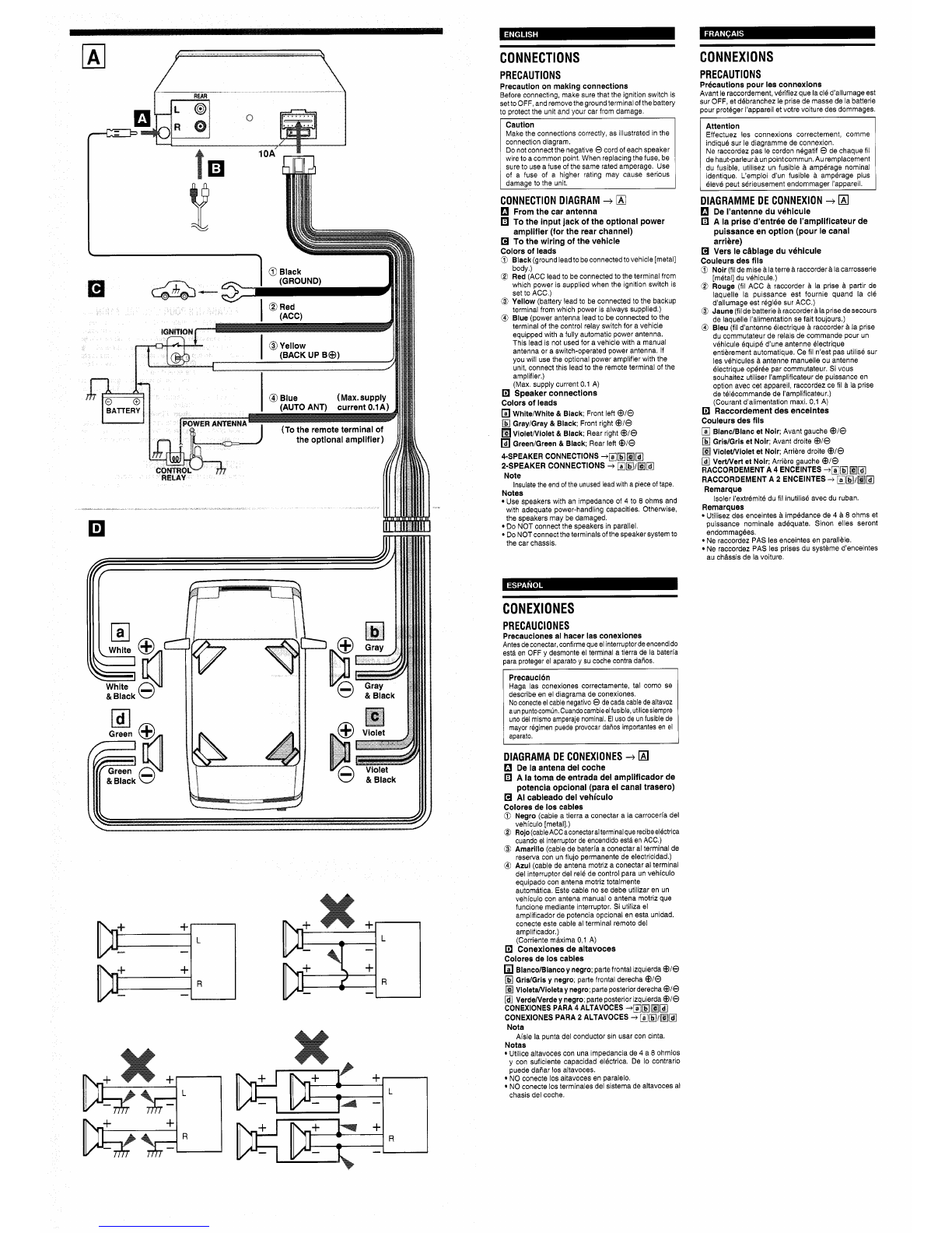
Aiwa CDC-Z137 User manual

3-251-499-ll(1)
FM/AM
Compact Disc
Player
CDC.2137
OPERATINGINSTRUCTIONS
-
MODE
D’EMPLOI
-
INSTRUCCIONES
DE
MANWO
DIGITAL
AUDIO
Owner’s
Record
For your convenience, recordthe serial number (youwill find
below. Pleaserefer
to
them when you contactyour
AlWA
visit
us
onthe-internet at
call tollfree
1-800-BUY-AIWA
(UnitedStates only)
them on the bottom side
of
your set) inthe space provided
dealer incase of difficulty.
Model
No.
CDC-Z137 Serial
No.
0
2003
Sony Corporation

PRECAUTIONS
Use only in a 12-volt DC negative-groundelectrical
system.
Disconnect the vehicle’s negative battery terminal
while mountingand connectingthe unit.
When replacingthe fuse, besure to use one with an
identicalamperage rating. Usingafuse with a higher
amperage rating may cause serious damage to the
unit.
DoNOTattempttodisassembletheunit.Laserbeams
from the optical pickupare dangeroustothe eyes.
Makesurethat pinsorotherforeignobjectsdonotget
insidetheunit;theymaycausemalfunctions,orcreate
safetyhazardssuchas electricalshockor laserbeam
exposure.
When your vehicle hasbeen parkedindirectsunlight
resulting in a considerable rise in the temperature
inside, allow the unitto cool
off
beforeoperatingit.
Keep the volume at a level at which you can hear
outsidewarningsounds (horns, sirens, etc.).
NOTE
This equipment has beentested and found to comply
with the limits for a Class B digital device, pursuantto
Part
15
of the FCC Rules.These limitsaredesignedto
provide reasonable protection against harmful
interferenceina residentialinstallation.
Thisequipment generates, uses,andcan radiateradio
frequency energy and,
if
not installed and used in
accordance with the instructions, may cause harmful
interferenceto radio communications. However,there
is
no
guarantee that interference will not occur in a
particular installation.
If
this equipment does cause
harmful interference to radio or television reception,
which can be determinedby turning the equipment
off
and on, the user is encouraged to try to correct the
interferenceby oneor moreof thefollowing measures:
-
Reorientor relocatethe receivingantenna.
-
Increasethe separation between the equipment
and receiver.
-
Connect the equipment into an outlet on circuit
differentfromthattowhichthereceiverisconnected.
-
Consult the dealer or an experienced radioFV
technicianfor help.
CAUTION
Modificationsor adjustmentstothis product,which are
notexpresslyapprovedbythe manufacturer,mayvoid
the user’s right or authorityto operatethis product.
bereadbythisunit.However, NEVERuseaCD-R or
CD-RW that contains no data or data in the wrong
Forinstallationandconnections,referto-theseparate
“INSTALLATIONAND CONNECTIONS:
TABLE
OF
CONTENTS
BASICOPERATION, AUDIO AND CLOCK
ADJUSTMENT
.....................................................
2
RADIOOPERATION
.................................................
3
CD PLAYEROPERATION
AUXILIARY EQUIPMENT
.
OTHER FUNCTION
..................................................
5
TROUBLESHOOTING
MAINTENANCE
........................................................
5
SPECIFICATIONS
....................................................
6
Note
Somebuttonsare assigned
two
or morefunctions.
For detaileddescriptions, referto the relatedpages.
CD
Notes
Playinga defectiveor dusty CD can
HoldCDsas illustrated.
Do NOTtouch the unlabeledside.
DoNOTattachanyseal,labelordataprotectionsheet
Do NOT expose a CD to direct sunlight or excessive
Wipe a dirty CD from the center outward with a
&
cause dropoutsinsound.
to either sideof CD.
heat.
cleaningcloth.
Never usesolventssuch as benzineor alcohol.
This unit cannotplay3-inch
(8
cm) CDs.
NEVER inserta3-inchCDcontainedintheadapteror
any irregularlyshaped CD.
The unit may not be able to eject it, resulting in a
malfunction.
Resetting
the
unit
Before operating the unit for the first time or after
replacingthe car battery,you must resetthe unit.
Pressthe resetbuttonwith a pointedobject such as a
pencil.
Resetbutton
Note
Pressingthe resetbuttonwill erasetheclockandsome
memorizedfunctions.
1
ENGLISH

BASICOPERATION,
AUDIO AND CLOCK
ADJUSTMENT
PWRIAT
I
sELJog dial (PUSH-SOURCE)
r,
I
DSPL
TU(TUNER)
+I-
Turning the unit onloft
Press
PWWAlT
to
turnonthe unit.The unitalsoturns
Press and hold
PWWAlT
until the unit turns
off.
on when you insert a
CD.
Mostoperationsdescribedinthis manualrequirethe
unit
to
be turned on before starting the operation,
unless explicitly stated otherwise.
Chanaina the source mode
1
Press
Jog
dial
(PUSH-SOURCE).
Pressing
Jog
dial
(PUSH-S0URCE)cyclesthrough
source modes in the following order:
TUNER (FMlIFM2/FMB/AMl/AM2)
+
CD*
+
AUX
f
I
*
"CD
does not appear inthe display when there is no
CD inthe unit.
Adiustina the volume
.a
1
Turn
Jog
dial.
VOLUME indicator appears.
Mutingthe sound
1
Press
PWFJAn
briefly.
ATindicator flashes.
To
restorevolume,
briefly press
PWWATT
again.
Adiustina sound
Press
SEL
repeatedly
to
select the mode to be
adjusted.
Pressing
SEL
cycles through the modes. The
selected mode's indicator appears.
Turn
Jog
dial to increase/decrease the level or
to
select onloff for the selected mode.
Note
Adjust the level or select on/off within
5
seconds, or the
selected mode will return
to
previous state.
Alianina the source levels
(Source Level Adjuster)
Volume may vary each time you change the source
mode. Inthis case, you can align each source mode's
volume
to
almost the same level.
1
Press
Jog
dial
(PUSH-SOURCE)
or
TU
(TUNER)
repeatedly
to
select the desired mode.
2
Press
DSPL
while pressing
SEL.
"LA
0
appears onthe display.
3
Turn
Jog
dial to
adjust the level.
Note
Adjust the levelwithin
5
seconds, or the selected mode
will be canceled.
Restoringthe factory settings
1
Turn off the unit.
2
Press and hold
DSPL
until
"LA
--"
appears on the
display.
Note
You
can restore the factory settings only for VOL,
BASS, TRE, BAL, FAD, and H-BASS, and aligned
source volume levels.
Setting the beep tone
1
Turn
off
the unit.
2
Press and hold
SEL
until "bEEP appears on the
display.
3
Turn
Jog
dial
to
select on (level indicators appear)
or
off
(level indicators disappear).
4
PressSEL.
You
can select thefollowing modesfor adjusting sound
depending on the music you listen
to:
BASS (low
frequencies), TRE (high frequencies), BAL (leftlright),
FAD (fronilrear) and H-BASS (high bass).
ENGLISH
2

Settingthe
clock
1
Pressand hold DSPL until the clock indicator
flashes in the display.
2
Press
+
(to
set
hour)or-
(to
set minute),andthen
turn Jog dial.
3
Press DSPL.
Displayingthe
clock
1
PressDSPL.
To returntothe former display, press DSPL again.
RADIO OPERATION
Tuning in to a station
(SeeWManual Tuning)
-0
+/-
TU (TUNER)
Local indicator Stereo indicator
Band indicator Frequency TUNER
indication indicator
1
PressTU(TUNER) repeatedly
to
selectthe desired
band (FMI
,
FM2, FM3, AMI, or AM2).
2*
Press
+
(to
move to higher frequencies) or
-
(to
move
to
lowerfrequencies)
to
tune in
to
a station.
"STEREO appears on the display when an FM
station is broadcasting in stereo, and receiving
conditions are good.
*Seek Tuning and ManualTuning
Press and hold
+
or
-
until seek Tuning starts.
The unitlocatesastationautomatically (SeekTuning).
Press
+
or
-
repeatedly
to
searchfor a desiredstation
while increasing or decreasing the frequency step by
step (ManualTuning).
To stop Seek Tuning, press
+
or
-
again.
Monaural mode
When signals become weak, or
FM
reception becomes
poor,the unitautomaticallyswitches
to
Monauralmode
to reduce noise.
Local mode
Localmodeallowsyou
to
tune in only
to
strongstations
during Seek Tuning.
1
Press LObefore you start seek tuning.
"LOCAL" appears on the display.
To return to Distant mode, press LO again.
"LOCALdisappearsandtheunittunesintoallreceivable
stations.
Using preset stations
Youmustpresetstationsbeforeyoucantuneinastation
using preset station number buttons.
+/-
I
TU (TUNER) Preset station buttons 1
to
6
PS/A.M
E
Preset station number
Presettingstations automatically
(Auto Memory)
1
PressTU (TUNER) repeateoly
to
se
ect the oes red
band (FM1,FM2 FM3,AM1, or AM2)
2
Press and nodPS/A.ME Jnti automatic presett ng
starts
Tne unit aJtomatical y stores
LP
to
6
stations for
each band
After complet on of aLtomatic presetting tne
,n
t
unes n
to
the stat on stored on preset station
bJnon 1
Tocancelautomaticpresetting,pressPS/A.ME again
Checking thepreset stations (Preset Scan)
1
Press PS/A.ME or
ef
y
Each preset stationw
11
betuned infor
5
seconds
n
oroer
To cancel Preset Scan, press PS/A.ME aga n or any
preset staton oJtton
3
ENGLISH

Presettingstations manually
(Manual Memory)
1
Press
TU(TUNER)
repeatedly
to
selectthe desired
band
(FMI, FM2, FM3, AMI,
or
AM2).
2
Press
+
or
-
to
tune in
to
a desired station (see
"Tuning in
to
a station'' as well for another tuning
method).
3
Pressandholdthe desiredpresetstation button until
the unit beeps.
Note
A
newly preset station replaces the station onthesame
bandthat was previously stored on that preset station
button.
Tuning in to
a
preset station
1
Press
TU (TUNER)
repeatedly
to
selectthe desired
band
(FM1, FM2, FM3,AM1
or
AMZ).
2
Pressthe presetstation buttononwhich thedesired
station is stored.
Active tuning reception control
(ATRC)
The unitautomatically suppresses
FM
noise causedby
vehicle movement, and maintains sound quality.
CD
PLAYER OPERATION
Playinga
CD
You
can play CDs, CD-Rs and CD-RWs using the
procedure described below
INT REPl
SHUF
1
Insert a CD.
CD indicator appears on the display.
CD play starts.
If a CD is already inserted, press
Jog
dial(PUSH-
SOURCE)
repeatedly
to
select CD play mode.
In normal play, when the last trackfinishes, the unit
returns
to
the first track and continues to play.
Labeled-side
up
Track number
Elapsed playing time CD indicator
To
Press
..
Eiect a CD
A
SkiD
to
the next track
W/W
Go
backto the beginning
of the current track
Each extra press skips
backward one extra track
Locate a specific point in
a track
Mi44
Press and hold
Mi44
or
W/W
until
you
find
the point.
Note
When you play a CDthat is already inserted, CD play
starts atthe point where it stopped the previous time.
A
newly inserted CD starts from the first track.
A
CD-Ror CD-RW maytake sometime
to
start playing
back, but this is not a malfunction.
If aCD-Ror CD-RWwith nodata
is
inserted,"E03will
appear inthe display. The unitcannot play suchdiscs.
lntro Play
You
canlocatea desiredtrack by monitoringthefirst 10
seconds
of
all the tracks on a CD.
1
Press
INT
during CD play.
"INTRO
appears on the display.
2
Press
INT
againwhen the desired track is played.
The unit returns
to
normalCD play.
Onetrack Repeat Play
You
can play a track repeatedly.
1
Press
REPl
during CD play.
"REPI" appears on the display.
To cancelOne track Repeat Play,
press
REPl
again.
ENGLISH
4

Shuffle
Play
You
can play all the tracks in random order.
1
To
cancelShuffle Play,
press
SHUF
again
Note
During Shuffle Play, pressing
HI
allows you
to
skip
only
to
the beginning of the current track,
not
to
the
previoustrack.
Press
SHUF
during CD play.
"SHUFappears on the display.
AUXILIARY EQUIPMENT
Listeningto a cassettelMDlMP3 portable
Dlaver or other eauiDment
You
canlisten
to
equipmentconnected
to
the unit.Refer
to the operating instructions for the corresponding
equipmentfor more detailed information.
Be sure
to
remove inserted CDs to prevent possible
damage
to
the unit before connecting the equipment.
Jog dial'(PUSH-SOURCE) AUX jkk
1
Connectacassette/MD/MP3portableplayerorother
equipment
to
the unit's AUX jack
(3.5
mm dia.).
2
Press
Jog
dial (PUSH-SOURCE)
repeatedly until
"AUX appears on the display.
DuringAUX mode, the clock display appears.
OTHER FUNCTION
SEL
I
6s
Jog dial (PUSH-SOURCE)
Settingthe dimmer of the display
1
Pressand hold
SEL
until
"D
appears inthe display.
2
Turn
Jog
dial
to
select
"0
(bright)"or
"1
(dimmed)."
Displayingthe
VU
level indicator
1
Turn
off
me unit
2
Pressand nolo
PS
until
"VII"
appears nthe oispay.
3
TJrn
Jog
dial
to
select on (leve naicators appear)
or
off
(level indcators dsappear)
4
Press PS.
TROUBLESHOOTING
Error
code
In the following cases the corresponding error code
indication appears. Follow the suggestions below
to
solve such problems.
ED3
Focuserror.CheckthattheCDisloadedproperly
(right side up, etc.), and the CD contains valid
data.
Reset button
If
aCDdoesnotoperateproperly,pressthe resetbutton
with a pointed object such asa pencil, etc. Notethat all
your settings will be erased
if
this button is pressed.
Reset
button
MAINTENANCE
Cleaning the front panel
Wipethe surfacewith a
soft,
dry cloth. Do not useliquid
cleaners
or
aerosol cleaners.

SPECIFICATIONS
RADIO
SECTION
(FM)
FrequencyRange: 87.5
MHz
-
108
MHz
UsableSensitivity: 12.7
dBf
50
dB Quieting Sensitivity: 17.2
dBf
IFRejection: 100
dB
FrequencyResponse:
30
Hz
-
15,000
Hz
SIN
Ratio: 70
dB
StereoSeparation:
35
dBat
1
kHz
AlternateChannelSelectivity:
90
dB
CaptureRatio:
3
dB
FrequencyRange:
530
kHz
-
1,710
kHz
UsableSensitivity:
30
VV
(30
dB)
CD
SECTION
FrequencyResponse: 17
Hz
-
20
kHz
+O/-3
dB
DynamicRange:
Morethan
85
dB
ChannelSeparation:
Morethan
60
dB
S/N
Ratio:
Morethan
90
dB
WowlFlutter:
Unmeasurable
AUDIO
SECTION
Max. PowerOutpuk45
W
x
4
channels
AUX
input
Inputsensitivity(load impedance)
AUX
300
mV
(10
@4
GENERAL
Power-SupplyVoltage: 14.4
V
(11
to
16
V
allowable),
DC,
negativeground
LoadImpedance:
4
R
ToneControl:
Bass~10dBatlOOHz,TrebleilOdBat10kHz
PreampOutput Voltage (load impedance): 2.2
V
Installedsize:
I82
(W)
x
53
(H)
x
155
(0)
mm
(7
Specificationsandexternalappearancearesubjectto
changewithout noticedue to productimprovement.
(AM)
(10
w
(W)
x
2
'18
(H)
x
6
l/8
(D)
inches)
ENGLISH
6

LIMITEDWARRANTY
Aiwa Strategic Accounts Partnership Inc. (“Aiwa”) warrants to the original consumerpurchaserthat this
productis
free
of
detects in material and workmanship at the time
of
purchase.
WARRANTY PERIODS
During the applicable LABOR warranty period, Aiwa will pay labor and service charges for the repair of
defects or, at its option, will replacea defective product with a new or remanufactured equivalent product.
During the applicable PARTS warranty period, Aiwa will supply at no charge new or rebuilt replacement
parts in exchange for defective parts. However, after the LABOR warranty period, all labor and service
charges are your responsibility. Replacementparts are warranted for the remainder of the original PARTS
warranty period.
The LABOR and PARTS warranty periods for your product are listed below.
All warranly periods
commence with the purchase date.
LABOR PARTS
Car Audio
1
year 1year
WHO PERFORMSAIWAS WARRANTY?
Aiwa’s warranty obligations must be performed by an Aiwa Authorized Service Center. For the name of the
Aiwa Authorized Service Centernearest
to
you call
toll
free 1-800-289-2492
(1
-800-BUY-AIWA).
WHAT YOU MUST
00
To obtain warranty performance, you must take the product, or deliver the product freight prepaid,
to
an
Aiwa Authorized Service Center. If shipped, the product must be packaged
so
that
it
is protected from
possible shipping damage. You must pick up the product when warranty performance is completed or, if
you choose, and the product was received by the Service Center during the LABOR warranty period,
the
repaired product will be returned
to
you freight prepaid. You must present
to
the Service Center, or include
with your shipment, a dealer’s bill of sale, or other original evidence, showing the date and place of
purchase and describing the product purchased. Be sure
to
include your return address and daytime
telephone number whereyou can be reachedshould the need arise.
WHAT THE WARRANTYDOES NOT COVER
This warranty does not cover (1) products purchased outside of the U.S.A.; (2) product set-up, adjustment
of controls, repair of antenna systems outside the unit;
(3)
removal or reinstallation, batleries, carrying
case, AC adapters and other accessories packaged with the product; (4) defects occurring after purchase
due
to
repair or service other than by an Aiwa Authorized Service Center, product modification, accident,
misuse, abuse, or negligence: or
(5)
reception problems caused by signal conditions, or cable or antenna
systems outside the unit. This warranty will not apply if the serial number of the unit has been altered or
removed.
REPAIR
OR
REPLACEMENT AS PROVIDED IN THIS WARRANTY
IS
THE PURCHASER’S EXCLUSIVE
WARRANTY REMEDY. IMPLIED WARRANTIES, INCLUDING THE WARRANTIES
OF
MERCHANTABILITY
AND
OF
FITNESS FOR A PARTICULAR PURPOSE, SHALL NOT EXTEND BEYOND THE DURATION OF THE
APPLICABLE PARTS WARRANTY PERIOD. IN NO EVENT SHALL AlWA BE LIABLE FOR INCIDENTAL
OR
CONSEQUENTIAL DAMAGES INCONNECTIONWITH THISPRODUCT. ,Somestates do notallow limitations
on how long an impliedwarranty lasts or the exclusion or limitation of incidental or consequential damages,
so
the above limitations or exclusion may not apply
to
you. This warranty gives you specific legal rights.
and you may also haveother rightswhich mayvary from state
to
state.
IF
YOU NEED HELP:
For the latest in Product Information, Parts, Service Center listings and F.A.Q.
information visit
us
on the web at www.us.aiwa.com or call
1
-800-BUY-AIWA.
For
further Aiwa information, please call 1-800-BUY-AIWA.
Visit
us
on the Internet at www.us.aiwa.com
D
455724401
http:llwww.aiwa.coml
Sony
Corporation
Printed
in
Thailand

A\i!!!
I
N
STALLATlO
N
AN
D
C
0
NN
ECTI
0
N
S
INSTALACION
Y
CONEXIONES
INSTALLATION ET CONNEXIONS
Sony Corporation
@
2003
Printed inThailand
3-251-494-1
1
(2)
.
SUPPLIED MOUNTING HARDWARE
FOR
INSTALLATION
+
W
MATERIEL
DE
MONTAGE FOURNI POUR
L'INSTALLATION
+
W
I
N
STALLAT
I
0
N
S
The installation scenario described in this manual
assumes that you have a typical car. If your specific car
requires any adjustments or modifications, consult your
nearest AlWA car audio dealer.
PRECAUTIONS
*This unit is designed for negative-ground,
12-V
DC
operation only.
Beforestarting installation,makesuretheignitionswitch
isset
to
OFF
and disconnect the groundterminal of the
car battery
to
avoid short-circuiting.
Installthe unitwhere it will not hamperthe operation of
the vehicle.
Install the unit where it will not injure the passenger
if
there is a sudden stop, like an emergency stop.
Avoid installingtheunitwhere
it
wouldbesubject
to
high
temperatures caused by direct sunlight or hot air from
the heater, or where it would be subject
to
dust,dirt or
excessive vibration.
Use only the supplied mounting hardware, for a safe
and secure installation.
PREINSTALLATIONS
+
DZ
If there is installation hardware for another receiver
already inthe dashboard, it must be removed.
Before installingthe unit in the dashboard
Removethe trim plate from the unit
+
0
FIX (fixedpanelktype model
Removethe trim plate
0
by pushing the upper and lower parts of the plate in
the direction of the arrow.
Asforthe
DFP(DetachableFrontPanel)-typemodel
and
FLAP (flap panelktype model,
the trim plate is
separately packed at the factory.
Removethe installationsleeve
+
Insertthe levers
@
along each groove on both sides of
the unit
to
unlock the installation sleeve
0
and pullthe
sleeve
to
detach it from the unit.
BASIC INSTALLATIONS
+
Installation in the dashboard
Notethat the Installation shown is a typical example.
For some cartypes you may need
to
make adjustments
or modifications
to
install the unit. If your car is of such
type, consult your nearest AlWA car audio dealer.
Mounting-angleadjustment
The mounting angle should be
30
degrees or less from
horizontal.
Caution
on
installation without
using
the
sleeve
+
IE
Be sure
to
use the supplied screws
@
shownin
LK
toattachthe mountingbrackets
@
(not supplied).
ACCESORIOS DE MONTAJE SUMINISTRADOS
PARA LA INSTALACION
+
W
INSTALACION
Lainstalaciondescritaa
lo
largode estemanualpresupone
que tiene un coche normal. Si
su
coche requiere ajustes
o
modificaciones,consultecon
su
concesionariode audio
para coches deAlWA mas cercano.
Este aparato fue disefiado para una conexion a tierra
negativa y funciona con una CC de
12
V.
Antes de empezar la instalaci6n, compruebe que el
interruptor de encendido esta en OFF y desconecte el
terminal atierra de la bateria de coche para evitar que
se produzca un cortocircuito.
lnstale el aparato donde no moleste
el
funcionamiento
del vehiculo.
lnstale el aparato en un lugar donde no provoque
heridasa
10s
pasajeros por unfrenado repentino,como
en el caso de un frenado
de
emergencia.
Evite instalar elaparato donde quede expuesto a altas
temperaturas provocadas por
10s
rayos directos del
sol
o
el aire caliente delacalefaccion
o
donde puedaestar
expuesto al polvo, suciedad
o
vibraciones excesivas.
Utilice
solo
10s
accesorios de montaje suministrados,
para una instalacion firme y segura.
PRECAUCIONES
INSTALACION PREVIA
+
DZ
Siyasehaninstaladoaccesorios parainstalaciondeotro
aparato en el tablero, debera desmontarlos.
Antes de instalar el aparato en el cubretablero
Desmonte la placa de adorno del aparato
+
0
Modelode tipo FIX(panelfijo)
Desmonte laplacade
adorno
0
empujando las partes superior e inferior de
la placa en el sentido de la flecha.
*Para el
modelo de tipo DFP (Panel frontal
desmontable)
y el
modelo de tipo FLAP (Panel de
aleta),
laplaca de adorno se empaquetapor separado
en la fabrica.
Desrnonte el manguitode instalacion
+
H
lnsette las palancas
@
a
lo
largo de cada ranura en
ambos lados del aparato para destrabar el manguito de
instalacion
0
ytire del manguito para desmontarlo de la
del
aparato.
INSTALACION BASICA
+
lnstalacionen el tablero
Tenga en cuenta que lainstalacion que se describe esa
modo
de ejemplo. Para algunos modelos de coche,
puede ser necesario hacer ajustes
o
modificaciones
para instalar el aparato. Si
su
coche es de este tipo,
consulte con
su
concesionario deaudio para coches de
AlWA mas cercano.
Ajuste del dngulo de rnontaje
Elangulo demontaje debe serde
30
grados
o
menosde
la horizontal.
utilizar
el
manguito
--f
Se deben utilizar siempre
10s
tornillos
suministrados
@
que aparecen en para
instalar las rnensulas de montaje
6
(no
suministradas).
I
N
STALLATlO
N
Le scenario d'installation indique dans ce manuel
presupposeunevoiture typique. Sivotrevoiture exige un
ajustement
ou
une modification, consultez le revendeur
de chaine audio automobile AlWA le plus proche.
PRECAUTION
Cetappareilestconquuniquementpourlefonctionnement
sur courant continu
12V,
masse negative.
Avant de commencer I'installation, verifiez que le
commutateurd'allumageestregleaOFFetdeconnectez
le prise de masse de la batterie auto pour eviter
tout
court-circuit.
lnstallez I'appareil
a
un endroit
OD
il
ne genera pas le
fonctionnement de la voiture.
lnstallez I'appareil
a
unendroit
ob
il
ne blessera pas le
passager, en cas d'arr6t brutal, par exemple un arr6t
d'urgence.
Evitezd'installerI'appareil un endroiten pleinsoleil
ou
sous
I'air chaud du chauffage,
ob
il
sera sournis
a
des
temperatures elevees,
ou
bien
a
un endroit
ou
il
sera
soumisaunepoussiere,delasaleteoudeforlesvibrations.
Utilisez seulement le materiel de montage fourni pour
assurer une installation sheet solide.
PREPARATIFS POUR L'INSTALLATION
-+
DZ
S'il y a deja du materiel de montage pour un autre
recepteur dans le tableau de bord,
il
doit 6tre retire.
Avant d'installer I'appareildans le tableaude bord
Retirez la plaque d'ajustementde I'appareil
+
0
Modhlede type FIX (panneaufixe)
Retirez la plaque
d'ajustement
0
en poussant les parties haut et basde
la plaque dans le sens de la fleche.
Commepour le modblede
typeDFP(panneauavant
amovible)
et le modele de
type FLAP (panneau
basculant),
la plaque d'ajustement est emballee
separement a I'usine.
Retirez le manchon d'installation
+
H
lnserez lesleviers
@
lelongdechaquecanneluresurles
deux cBt6s de I'appareil pour debloquer le manchon
d'installation
0,
puistirezsurlemanchonpourledetacher
de
I'appareil.
INSTALLATION DE BASE
+
Installationdans le tableau de bord
Pour cettains types de voiture,
il
faudra peut-6trefaire
desajustements
ou
modificationspourinstallerI'appareil.
Sic'estle cas pour votre voiture, consultez le revendeur
de chainesaudio automobiles AlWA le plus proche.
Ajustement de I'angle de montage
L'angle de montage doit 6tre de
30'
ou
moins de
I'horizontale.
Precaution
pour
I'installation
sans
manchon
+
Utilisezles vis fournies
@
indiqueesdans
pourattacher lesfixations demontage
@
(non
fournies).

I
CONNECTIONS
PRECAUTIONS
Precautionon making connections
Before connecting, make sure that the ignition switch is
settoOFF,and removethe groundterminal of the battery
to
protect the unit and your car from damage.
Caution
Makethe connections correctly, as illustrated in the
connection diagram
Do
not connect the negative
0
cordof each speaker
wireto a common point When replacingthe fuse, be
sure
to
usea fuse of the same rated amperage Use
of a fuse of a higher rating may cause serious
CONNECTION DIAGRAM
+
From the car antenna
Tothe input jack of the optional power
H
To
the wiring of the vehicle
Colors of leads
3
Black(groundleadtobeconnectedtovehicle [metal]
3
Red
(ACC lead
to
be connected
to
the terminal from
which power
is
supplied when the ignition switch is
set
to
ACC
)
@
Yellow
(battery lead
to
be connected to the backup
terminal from which power
is
always supplied
)
@
Blue
(power antenna lead
to
be connected to the
terminal of the control relay switch for a vehicle
equipped with a fully automatic power antenna
This lead
is
not used for a vehicle with a manual
antenna or a switch-operated power antenna
If
you will use the optional power amplifier with the
unit, connect this lead
to
the remote terminal of the
amplifier
)
(Max supply current
0
1
A)
0
Speaker connections
Colors of leads
Whitewhite
&
Black,
Front left
@/@
Gray/Gray
&
Black,
Front right
@/O
VioleWiolet
&
Black,
Rear right
@/O
GreeniGreen
&
Black,
Rear left
$10
amplifier (for the rear channel)
body
)
4-SPEAKER CONNECTIONS
+E
2-SPEAKER CONNECTIONS
+
Note
Notes
Use speakers with an impedance of
4
to
8
ohms and
with adequate power-handling capacities Othewise,
the speakers may be damaged
Do NOT connect the speakers in parallel
Do
NOTconnect theterminals of thespeakersystem
to
the car chassis
Insulatethe end of the unused leadwith a piece of tape
CONEXIONES
PRECAUCIONES
Precaucionesal hacer las conexiones
Antesde conectar,confirmequeel interruptordeencendido
esta en OFF y desmonte el terminal a tierra de la bateria
paraproteger el aparato y
su
coche contradaiios.
Haga las conexiones correctamente, tal como se
describe en el diagrama de conexiones.
No
conecteel cable negativo
0
de cadacable de altavoz
aunpuntocomun.Cuandocambieelfusible,utilicesiempre
uno del mismo amperaje nominal.
El
us0
de unfusible de
mayor regimen puede provocar daiios importantes en el
aparato.
DIAGRAMA DE CONEXIONES
+
61
De la antena del coche
A
latoma de entrada del amplificador de
potencia opcional (para el canal trasero)
H
Al
cableado del vehiculo
Coloresde
10s
cables
0
Negro
(cable a tierra a conectar a la carroceria del
vehiculo [metal]
)
@
Rojo
(cableACCaconectaralterminalquerecibeelectrica
cuando el interruptorde encendidoesta en ACC
)
0
Amarillo
(cable de bateriaa conectar al terminal de
reserva con un flujo permanente de electricidad
)
@
Azul
(cable de antena motriz a conectar al terminal
del interruptor del rele de control para unvehiculo
equipado con antena motriz totalmente
automltica Este cable no se debe utilizar en un
vehiculo con antena manual
o
antena motriz que
funcione mediante interruptor
Si
utiliza el
amplificador de potencia opcional en esta unidad
conecte este cable al terminal remoto del
amplificador
)
(Corriente maxima
0
1
A)
0
Conexiones de altavoces
Coloresde
10s
cables
BlancolBlanco
y
negro,
partefrontal izquierda
@I@
GrislGris
y
negro
parle frontal derecha
$10
VioletaNioleta
y
negro,
parteposteriorderecha
@/@
VerdeNerde
y
negro,
parteposteriorizquierda
@/Q
CONEXIONES
PARA
4
ALTAVOCES
+E
CONEXIONES PARA
2
ALTAVOCES
+
Nota
Aisle la punta del conductor sin usar con cinta
Notas
Utilice altavoces con una impedancia de
4
a
8
ohmios
y con suficiente capacidad electrica De
lo
contrario
puededaiiar
10s
altavoces
NO
conecte
10s
altavoces en paralelo
NOconecte
10s
terminales del sistema de altavoces al
chasis del coche
CONNEXIONS
PRECAUTIONS
Precautionspour les connexions
Avant le raccordement, verifiez que lacled'allumage est
sur OFF, et debranchez leprise de masse de la batterie
pour proteger I'appareil et votre voiture des dommages.
Effectuez les connexions correctement, comme
indique sur le diagramme de connexion.
Ne raccordez pas le cordon negatif
O
de chaque
fil
dehaut-parleurAun pointcommun.Au remplacement
du
fusible, utilisez un fusible
a
amperage nominal
identique. L'emploi d'un fusible
a
amperage plus
eieve Deut serieusement endommager I'appareil.
DIAGRAMME DE CONNEXION
+
DeI'antenne du vehicule
0
A
la prise d'entree de I'amplificateur de
puissance en option (pour le canal
arriere)
H
Vers le ciblage du vehicule
Couleursdes fils
0
Noir
(filde mise laterre
a
raccorderalacarrosserie
[metal]
du
vehicule.)
@
Rouge
(fil ACC raccorder
a
la prise
a
partir de
laquelle la puissance est fournie quand la cle
d'allumage est reglee sur ACC.)
@
Jaune
(fildebatteriearaccorderalaprisedesecours
de laquelle I'alimentation se fait toujours.)
@
Bleu
(fild'antenne electrique
a
raccorder
A
la prise
du commutateur de relais de commande pour un
vehicule Bquiped'une antenne electrique
entierement automatique. Ce
fil
n'est pas utilise sur
les vehicules antenne manuelle
ou
antenne
electrique operee par commutateur. Si vous
souhaitez utiliser I'amplificateur de puissance en
option avec cet appareil, raccordez ce
fil
a
la prise
de telecommande de I'amplificateur.)
(Courant d'alimentation maxi. 0,1 A)
0
Raccordement des enceintes
Couleursdes fils
BlanclBlancet Noir;
Avant gauche
@/@
Gris/Griset Noir;
Avant droite
810
VioleWiolet et Noir;
Arriere droite
8/O
VerVVert et Noir;
Ar
'
RACCORDEMENTA 4
RACCORDEMENT A
2
Remarque
Remarques
Utilisez des enceintes
a
impedance de
4
a
8
ohms et
puissance nominale adequate. Sinon elles seront
endommagees.
Ne raccordez PAS les enceintes en parallele.
Ne raccordez PAS les prises
du
systeme d'enceintes
au chassis de lavoiture.
lsoler I'extremite du
fil
inutilise avec du ruban.
Other manuals for CDC-Z137
2
Table of contents
Other Aiwa Car Receiver manuals