Aiwa CT-R442 User manual

SERVICE MANUAL
FM/MW/LW CASSETTE CAR STEREO
AEP Model
UK Model
SPECIFICATIONS
CT-R442
Ver 1.0 2003.03
Model Name Using Similar Mechanism CT-X442
Tape Transport Mechanism Type CDS-363AG1-A
9-877-102-01 Sony Corporation
2003C0500-1 e Vehicle Company
C2003.03 Published by Sony Engineering Corporation
RADIO SECTION
(FM)
Frequency Range: 87.5 MHz – 108 MHz
Intermediate frequency: 10.7 MHz
Usable Sensitivity: 12.7 dBf
50 dB Quieting Sensitivity: 17.2 dBf
IF Rejection: 100 dB
Frequency Response: 30 Hz – 15,000 Hz
S/N Ratio: 67 dB
Stereo Separation: 35 dB at 1 kHz
Alternate Channel Selectivity: 90 dB
Capture Ratio: 3 dB
(MW)
Frequency Range: 531 kHz – 1,602 kHz
Intermediate frequency: 10.71 MHz/450 kHz
Usable Sensitivity: 30 µV (30 dB)
(LW)
Frequency Range: 144 kHz – 288 kHz (1-kHz/9-kHz
steps)
Intermediate frequency: 10.71 MHz/450 kHz
Usable Sensitivity: 30 µV (30 dB)
TAPE SECTION
Tape Speed: 4.8 cm/sec.
S/N Ratio: 50 dB
Frequency Response: 40 Hz – 14,000 Hz
Stereo Separation: 40 dB
AUDIO SECTION
Max. Power Output: 40 W ×4 channels
AUX input
Input sensitivity (load impedance) AUX: 300 mV
(10 kΩ)
GENERAL
Power-Supply Voltage: 14.4 V (11 to 16 V
allowable), DC, negative ground
Load Impedance: 4 Ω
Tone Control: Bass ± 10 dB at 100 Hz, Treble
± 10 dB at 10 kHz
Preamp Output Voltage (load impedance): 2.2 V
(10 kΩ)
Installed size: 182 (W) ×53 (H) ×155 (D) mm
Supplied Accessory: Carrying case (1)
•Specificationsandexternalappearancearesubjectto
change without notice due to product improvement.

2
CT-R442
Notes on chip component replacement
•Never reuse a disconnected chip component.
•Notice that the minus side of a tantalum capacitor may be dam-
aged by heat.
Flexible Circuit Board Repairing
•Keep the temperature of the soldering iron around 270 ˚C dur-
ing repairing.
•Do not touch the soldering iron on the same conductor of the
circuit board (within 3 times).
•Be careful not to apply force on the conductor when soldering
or unsoldering.
TABLE OF CONTENTS
1. GENERAL ................................................................... 3
2. DISASSEMBLY
2-1. Disassembly Flow ........................................................... 7
2-2. Mechanical Deck Assy (CDS-363AG1-A)..................... 8
2-3. Sub Panel Assy ................................................................ 9
2-4. MAIN Board ................................................................... 10
3. ELECTRICAL ADJUSTMENT............................ 11
4. DIAGRAMS
4-1. Note for Printed Wiring Boards and
Schematic Diagrams ....................................................... 12
4-2. Printed Wiring Board – MAIN Board – ........................ 13
4-3. Schematic Diagram – MAIN Board (1/3) – .................. 14
4-4. Schematic Diagram – MAIN Board (2/3) – .................. 15
4-5. Schematic Diagram – MAIN Board (3/3) – .................. 16
4-6. Printed Wiring Boards – KEY/AUX Boards –.............. 18
4-7. Schematic Diagram – KEY/AUX Boards – .................. 19
4-8. IC Pin Function Description ........................................... 20
4. EXPLODED VIEWS
4-1. Main Section ................................................................... 22
4-2. Front Panel Section ......................................................... 23
5. ELECTRICAL PARTS LIST ............................... 24

3
CT-R442
SECTION 1
GENERAL This section is extracted from
instruction manual.
ENGLISH
2
ENGLISH
2
THEFT PROTECTION
Take the front panel with you when leaving the car, and
keep it in the supplied carrying case.
Detaching the front panel
Beforedetachingthefrontpanel,removethecassetteto
prevent possible damage to the unit.
1Press zto remove the cassette.
2Press and hold PWR/MUTE until the unit turns off.
3Press %. (Hold the panel with one hand to prevent
accidentally dropping it.)
4Remove the panel.
Attaching the front panel
1Engagetheleftsideofthefrontpaneltotheleftcatch
on the unit.
2Push the panel forward until it locks. Be sure not to
pressanybuttons whileyouare attachingthepanel.
Note
Do not touch the connector on the reverse side of the
frontpanel.Thiscouldcauseapoororfaultyconnection.
BASICOPERATION,
AUDIO AND CLOCK
ADJUSTMENT
PWR/MUTE SEL
DSPL
TU (TUNER) SRC
AUDIO CONTROL
i
/
k
Turning the unit on/off
•Youcan turn theunit on bypressing any buttonon the
front panel except %, z, f, gand AUDIO
CONTROL. The unit also turns on when you insert a
cassette.
•Press and hold PWR/MUTE until the unit turns off.
Note
Most operations described in this manual require
theunittobeturnedonbeforestartingtheoperation,
unless explicitly stated otherwise.
Changing the source mode
1Press SRC.
Pressing SRC cycles through source modes in the
following order:
*Tape Play mode (available while a cassette is in the
unit)
Adjusting the volume
1Turn AUDIO CONTROL.
VOL (volume)
indicator flashes.
Muting the sound
1Press PWR/MUTE briefly.
MT indicator flashes.
To restore volume, briefly press PWR/MUTE again.
3
ENGLISH
3
ENGLISH
Adjusting sound
You can select the following modes for adjusting sound
depending on the music you listen to: BASS (low
frequencies), TRE (high frequencies), BAL (left/right),
FAD (front/rear) and H-BASS (high bass).
1Press SEL repeatedly to select the mode to be
adjusted.
Pressing SEL cycles through the modes. The
selected mode’s indicator flashes (except for H-
BASS).
2TurnAUDIOCONTROLtoincreaseordecreasethe
level for the selected mode (except for H-BASS).
In H-BASS mode, turn AUDIO CONTROL to select
1, 2, 3 or off.
Note
Adjust the level or select on/off within 5 seconds, or the
selected mode will return to previous state.
Aligning the source levels
(Source Level Adjuster)
Volume may vary each time you change the source
mode. In this case, you can align each source mode’s
volume to almost the same level.
1Press SRC or TU (TUNER) repeatedly to select the
desired mode.
2Press DSPL while pressing SEL.
“LEVEL 0” appears on the display.
3Turn AUDIO CONTROL to adjust the level.
Note
Adjust the level within 5 seconds, or the selected mode
will be canceled.
Restoring the factory settings
1Turn off the unit.
2Press and hold DSPL until “LEVEL --” appears on
the display.
Note
YoucanrestorethefactorysettingsonlyforVOL,BASS,
TRE, BAL, FAD, and H-BASS, and aligned source
volume levels.
Setting the beep tone
1Turn off the unit.
2Press and hold SEL until “BEEP” appears on the
display.
3Turn AUDIO CONTROL to select ON or OFF.
4Press SEL.
Setting the clock
1Press and hold DSPL until the clock indication
flashes in the display.
2Press i(to set hour) or k(to set minute) and
turn AUDIO CONTROL.
3Press DSPL.
Displaying the clock
1Press DSPL.
To return to the former display, press DSPL again.
RADIO OPERATION
Tuning in to a station
(Seek/Manual Tuning)
i
/
k
TU (TUNER)
Band indicator*
Stereo indicator Frequency indication
*“F” means FM.
ENGLISH
4
ENGLISH
4
1Press TU (TUNER) repeatedly to select the desired
band (F1, F2, F3, MW, or LW).
2* Press i(to move to higher frequencies) or k(to
move to lower frequencies) to tune in to a station.
“ST” appears on the display when an FM station is
broadcastingin stereo,andreceiving conditionsare
good.
*Seek Tuning and Manual Tuning
•Press and hold ior kuntil Seek Tuning starts.
The unit locates a station automatically (Seek
Tuning).
•Press ior krepeatedly to search for a desired
station while increasing or decreasing the frequency
step by step (Manual Tuning).
To stop Seek Tuning, press ior kagain.
Monaural mode
When FM signals become weak, or FM reception
becomes poor, the unit automatically switches to
Monaural mode to reduce noise.
Using preset stations
You must preset stations before you can tune in to a
station using preset station number buttons.
i
/
k
PS/A.ME
TU (TUNER)
Preset station buttons 1 to 6
Preset station number
Presetting stations automatically
(Auto Memory)
1Press TU (TUNER) repeatedly to select the desired
band (F1, F2, F3, MW, or LW).
2Press and hold PS/A.ME until automatic presetting
starts.
The unit automatically stores up to 6 stations for
each band.
After completion of automatic presetting, the unit
tunes in to all the stations stored on the preset
station buttons in order (Preset Scan).
Tocancelautomaticpresetting,pressPS/A.MEagain.
Checking the preset stations (Preset Scan)
1Press PS/A.ME briefly.
Each preset station will be tuned in for 5 seconds in
order.
To cancel Preset Scan, press PS/A.ME again or any
preset station button.
Presetting stations manually
(Manual Memory)
1Press TU (TUNER) repeatedly to select the desired
band (F1, F2, F3, MW, or LW).
2Press ior kto tune in to a desired station (see
“Tuning in to a station” as well for another tuning
method).
3Pressandholdthedesiredpresetstationbuttonuntil
the unit beeps.
Note
Anewly preset station replacesthe station onthe same
band that was previously stored on that preset station
button.
Tuning in to a preset station
1Press TU (TUNER) repeatedly to select the desired
band (F1, F2, F3, MW, or LW).
2Pressthe presetstationbutton onwhich thedesired
station is stored.
Active tuning reception control (ATRC)
The unit automatically suppresses FM noise caused by
vehicle movement, and maintains sound quality.
Radio data system (RDS) features
The following RDS features are available with this unit.
Important
•The RDS features are available only during FM
reception.
•Youmay not beable to activatethe RDS featuresfully
in the areas where the station is test-broadcasting the
RDS signals.
AUDIO CONTROL PS/A.ME
TA AF SEL
Tuning in to Alternative Frequency (AF)
stations
Thereareprograms transmittedatdifferent frequencies
indifferent areas.Along withthe programitself, anRDS
stationsendstheAFlistdatathatcontainsthefrequencies
sending the same program. If the signal of the tuned-in
frequencybecomes weakwhile youare driving,the unit
automaticallysearchesthesameprogramsentatanother
stronger frequency according to the AF list, so that you
do not have to seek and tune in to the other frequency
again.
1PressAFduringFMreceptiontoactivateAFfunction.
“AF” appears on the display.*
* “AF” flashes when the unit cannot receive AF list
data.
Tuning in to an EON*, Traffic Program (TP)
The unit automatically switches to FM reception and
tunesintoanEON,trafficannouncementprogramwhen
the program starts.
*EON: Enhanced Other Network
1PressTAduringFMreceptiontoactivateTPfunction.
“TP” appears on the display.*
During reception, “TA” appears on the display.
*“TP” flasheswhenthe unitcannot receiveTPdata.
To turn off TP function, press TA.
“TP” disappears.
Setting the volume of TP reception
WhenTPfunctionisactivated,thetrafficannouncement
program is tuned in at the volume set in the following
procedure regardless of the volume of the other source
at the time TP function is activated.
1Pressandhold AFuntil“BOOST 40”appearson the
display.
“BOOST 40” disappears approx. 5 seconds later.
2Turn AUDIO CONTROL to select a volume level (0
to 80 in increments of 5).
3Press SEL.
Activating AF function and TP function at the
same time
1Press AF, and then press TA.
“AF” and “TP” appears on the display.
Notes
•During MW or LW reception, the unit will not
automatically tune in to a traffic announcement
program. Be sure to select “F1/2/3,” “TAPE,” or “AUX
IN” to activate TP function.
•When the unit tunes in to a traffic announcement
program by way of TP function, you can increase the
volume, but cannot decrease it.
•When the traffic announcement program finishes, the
unit automatically returns to the previous state.
Tuning in to a station by specifying a
Program Type (PTY)
1Press and hold TA until “PRO-TYPE” appears on
the display.
“PRO-TYPE” disappears approx. 5 seconds later.
2While “PRO-TYPE” is displayed, press one of the
presetstation buttons*for morethan 0.5seconds to
select a Program Type.
Theunit starts tosearch for astation of theselected
Program Type and tunes in to the station.
*TheProgram Types areassigned tothe preset station
buttons as follows:
Preset station button Program Type (default)
1NEWS
2SPORT
3EDUCATE
4SCIENCE
5ROCK M
6CLASSICS
5
ENGLISH
Preset station buttons 1 to 6

4
CT-R442
Changing the Program Types assigned to
preset station buttons
You can assign one of the following Program Types to
each preset station button.
NEWS, AFFAIRS, INFO, SPORT, EDUCATE,
DRAMA, CULTURE, SCIENCE, VARIED, POP M,
ROCK M, EASY M, LIGHT M, CLASSICS, and
OTHER M
1Turn off the unit.
2Pressandhold TAuntil“PRO-TYPE” appearsinthe
display.
3While “PRO-TYPE” is displayed, turn AUDIO
CONTROL to select the desired Program Type.
4WhiletheselectedProgramTypeisdisplayed,press
adesiredpresetstationbuttonfor2ormoreseconds.
Adjusting the clock by Clock Time (CT)
service
Theunitadjuststheclock automaticallyaccordingtothe
CT data sent from a currently tuned-in RDS station.
1Press and hold TA, and then press AF during FM
reception.
“CT” appears in the display.
2Turn AUDIO CONTROL to select “CT ON.”
“CT”appearsinthedisplayandtheclockisadjusted.
To turn off CT function, select “CT OFF” in step 2.
Notes
•In the following cases, “CT” flashes and the clock will
not be adjusted:
—The tuned-in signal is too weak to activate this
function.
—The tuned-in station is not sending CT data.
•The clock may not always be correct even when CT
function is on.
Tips and other information
Presetting Alternative Frequency (AF) stations
automatically
Only the strongest frequencies among the AF stations
that are broadcasting the same program are selected
and assigned to each preset station button.
1During FM reception, make sure that “AF” and/or
“TP” appear(s) in the display (see “Tuning in to
AlternativeFrequency (AF) stations” and“Tuning in
to an EON Traffic Program (TP)”).
2Press and hold PS/A.ME until Auto Memory for AF
stations starts.
Displaying a Program Service (PS) name
You can check the name of currently tuned-in station in
thedisplay. When the unit istuned in toan RDS station
sending PS data, the station name appears in the
display.
Note
In the following cases, the station name will not appear
in the display:
—Thetuned-insignalistooweaktoactivatethisfunction.
—The tuned-in station is not sending PS data.
Notes on emergency broadcasts
•The unit automatically switches to FM reception and
tunesin to emergency broadcastwhen it starts.When
the broadcast finishes, the unit automatically returns
to the previous state.
•Be sure to turn on AF function and TP function to
receive emergency broadcasts.
•During MW or LW reception, the unit will not tune in
to the urgent broadcast.
ENGLISH
6
TAPEPLAYBACK
SRC
gfz
Playing a tape
1Insert a cassette to start playback.
If a cassette is already inserted, press SRC
repeatedly to select Tape Play mode to start
playback.
Playback starts in the direction that the unit played
back previously.
Press the following buttons to operate tape transport.
7
ENGLISH
To
Eject a cassette*
Change the playback side
Fast-forward the upper side
(l) of the tape
Rewind the lower side (j)
of the tape
Rewind the upper side (l)
of the tape
Fast-forward the lower side
(j) of the tape
Stop fast transport and
resume playback
Press
z
fand g
simultaneously
g
f
for glightly**
Auto Reverse function
Whenthe end of thetape is reached duringplayback or
fast tape transport, the direction of the tape is
automaticallyreversed,andplaybackstartsontheother
side.
Direction indications
Displayed when the upper side of the
cassette is being played.
Displayed when the lower side of the
cassette is being played.
Tape transport display
Upper side: During playback
Lower side: During playback
When you do not play back a tape
Be sure to eject any cassette.
To prevent tape problems
Before inserting a cassette into the unit, make sure that
there is no slack in the tape. If necessary, take up the
slack by inserting a pencil through the spindle hole and
winding.
Tapes of 90 minutes or longer are extremely thin and
easily deformed or damaged. They are not
recommended.
*When you ejectthe cassette, the unitswitches to the
previous mode.
** Do not press for gall the way. Doing so may
change the direction of tape transport.
AUXILIARY EQUIPMENT
Listening to a CD/MD/MP3 portable
player or other equipment
Youcanlistentoequipment connectedtotheunit.Refer
to the operating instructions for the corresponding
equipment for more detailed information.
Be sure to remove the inserted cassette to prevent
possible damage to the unit before connecting the
equipment.
SRC
AUX jack
1Connect a CD/MD/MP3 portable player or other
equipment to the unit’s AUX jack (3.5-mm dia.).
2PressSRCrepeatedlyuntil“AUXIN”appearsonthe
display.
OTHER FUNCTIONS
SRC SELAUDIO
CONTROL
Changing the contrast of the display
1Press and hold SRC until “CONT.” appears on the
display.
2Turn AUDIO CONTROL to select “L (for low)” or “H
(for high).”
Setting the dimmer of the display
1Press and hold SEL until “DIMMER” appears in the
display.
2Turn AUDIO CONTROL to select “0 (bright)” or
“1 (dimmed).”
Muting the sound while using the phone
When the telephone mute lead (light blue) of the unit is
connected to a cellular phone hands-free car kit, etc.,
the unit mutes the sound from the speakers
automatically during your conversation on the cellular
phone.
For details, refer to the separate “INSTALLATION AND
CONNECTIONS”fortheunitandtheinstructionmanual
for the cellular phone hands-free car kit.
ENGLISH
8

5
CT-R442
ENGLISH
SUPPLIED MOUNTING HARDWARE FOR
INSTALLATION →A
INSTALLATIONS
The installation scenario described in this manual
assumes that you have a typical car. If your specific car
requires any adjustments or modifications, consult your
nearest AIWA car audio dealer.
PRECAUTIONS
•This unit is designed for negative-ground, 12-V DC
operation only.
•Beforestartinginstallation,makesuretheignitionswitch
is set to OFF and disconnect the earth terminal of the
car battery to avoid short-circuiting.
•Install the unit where it will not hamper the operation of
the vehicle.
•Install the unit where it will not injure the passenger if
there is a sudden stop, like an emergency stop.
•Avoidinstallingtheunitwhereitwouldbesubjecttohigh
temperatures caused by direct sunlight or hot air from
the heater, or where it would be subject to dust, dirt or
excessive vibration.
•Use only the supplied mounting hardware, for a safe
and secure installation.
PREINSTALLATIONS →B
If there is installation hardware for another receiver
already in the dashboard, it must be removed.
Before installing the unit in the dashboard
Remove the trim plate from the unit →1
•FLAP (flap panel)-type model Remove the trim plate
abypushing thesideof theplate inthedirection ofthe
arrow.
•FIX (fixed panel)-type model Remove the trim plate
aby pushing the upper and lower parts of the plate in
the direction of the arrow.
•AsfortheDFP(DetachableFrontPanel)-typemodel,
the trim plate is separately packed at the factory.
Remove the installation sleeve →2
Insert the levers 8along each groove on both sides of
the unit to unlock the installation sleeve 1and pull the
sleeve to detach it from the unit.
BASIC INSTALLATIONS →C
Installation in the dashboard
Note that the Installation shown is a typical example.
For some car types you may need to make adjustments
or modifications to install the unit. If your car is of such
type, consult your nearest AIWA car audio dealer.
Mounting-angle adjustment
The mounting angle should be 30 degrees or less from
horizontal.
Caution on installation without using the
sleeve →D
Be sure to use the supplied screws 9shown
in Ato attach the mounting brackets M(not
supplied).
ESPAÑOL
ACCESORIOS DE MONTAJE SUMINISTRADOS
PARA LA INSTALACION
→A
INSTALACION
La instalación descrita a lo largo de este manual
presupone que tiene un coche normal. Si su coche
requiere ajustes o modificaciones, consulte con su
concesionario de audio para coches de AIWA más
cercano.
PRECAUCIONES
•Este aparato fue diseñado para una conexión a tierra
negativa y funciona con una CC de 12 V.
•Antes de empezar la instalación, compruebe que el
interruptor de encendido está en OFF y desconecte el
terminal a tierra de la batería de coche para evitar un
cortocircuito.
•Instale el aparato donde no moleste el funcionamiento
del vehículo.
•Instale el aparato en un lugar donde no provoque
heridasalos pasajeros porunfrenadorepentino, como
en el caso de un frenado de emergencia.
•Evite instalar el aparato donde quede expuesto a altas
temperaturasprovocadas porlos rayos directosdel sol
oel airecaliente de la calefacción o donde puedaestar
expuesto al polvo, suciedad o vibraciones excesivas.
•Utilice sólo los accesorios de montaje suministrados,
para una instalación firme y segura.
INSTALACION PREVIA →B
Siyasehaninstaladoaccesoriosparainstalacióndeotro
aparato en el tablero, deberá desmontarlos.
Antes de instalar el aparato en el cubretablero
Desmonte la placa de adorno del aparato →1
•Modelo de tipo FLAP (panel de aleta) Desmonte la
placa de adorno aempujandoel ladode laplaca enel
sentido de la flecha.
•Modelo de tipo FIX (panel fijo) Desmonte la placa de
adorno aempujando las partes superior e inferior de
la placa en el sentido de la flecha.
•Para el modelo de tipo DFP (Panel frontal
desmontable), la placa de adorno se empaqueta por
separado en la fábrica.
Desmonte el manguito de instalación →2
Inserte las palancas 8a lo largo de cada ranura en
ambos lados del aparato para destrabar el manguito de
instalación1y tiredel manguitopara desmontarlode la
del aparato.
INSTALACION BASICA →C
Instalación en el tablero
Tengaen cuenta quela instalaciónque se describe es a
modo de ejemplo. Para algunos modelos de coche,
puede ser necesario hacer ajustes o modificaciones
para instalar el aparato. Si su coche es de este tipo,
consulte con su concesionario de audio para coches de
AIWA más cercano.
Ajuste del ángulo de montaje
Elángulo demontaje debeser de30 gradoso menosde
la horizontal.
Precauciones sobre la instalación sin
utilizar el manguito →D
Se deben utilizar siempre los tornillos
suministrados 9que aparecen en A, para
instalar las ménsulas de montaje M(no
suministradas).
FRANÇAIS
MATERIEL DE MONTAGE FOURNI POUR
L’INSTALLATION →A
INSTALLATION
Le scénario d’installation indiqué dans ce manuel
présupposeunevoituretypique.Sivotrevoitureexigeun
ajustement ou une modification, consultez le revendeur
de chaîne audio automobile AIWA le plus proche.
PRECAUTION
•Cet appareil est conçu uniquement pour le
fonctionnement sur courant continu 12 V, masse
négative.
•Avant de commencer l’installation, vérifiez que le
commutateurd'allumageestrégléàOFFetdéconnectez
la prise de masse de la batterie auto pour éviter tout
court-circuit.
•Installez l’appareil à un endroit où il ne gênera pas le
fonctionnement de la voiture.
•Installez l’appareil à un endroit où il ne blessera pas le
passager, en cas d’arrêt brutal, par exemple un arrêt
d’urgence.
•Evitezd’installerl’appareilàunendroitenpleinsoleilou
sous l’air chaud du chauffage, où il sera soumis à des
températures élevées, ou bien à un endroit où il sera
soumis à une poussière, de la saleté ou de fortes
vibrations.
•Utilisez seulement le matériel de montage fourni pour
assurer une installation sûre et solide.
PREPARATIFS POUR L’INSTALLATION
→B
S’il y a déjà du matériel de montage pour un autre
récepteur dans le tableau de bord, il doit être retiré.
Avant d’installer l’appareil dans le tableau de bord
Retirez la plaque d’ajustement de l’appareil →1
•
Modèle de type FLAP (panneau basculant) Retirez la
plaque d’ajustement
a
en poussant le côté de la plaque
dans le sens de la flèche.
•Modèle de type FIX (panneau fixe) Retirez la plaque
d’ajustementaen poussant les parties haut et bas de
la plaque dans le sens de la flèche.
•Comme pour le modèle de type DFP (panneau avant
amovible), la plaque d’ajustement est emballée
séparément à l’usine.
Retirez le manchon d’installation →2
Insérezlesleviers8lelongde chaquecanneluresurles
deux côtés de l’appareil pour débloquer le manchon
d’installation1,puistirezsurlemanchonpourledétacher
de l’appareil.
INSTALLATION DE BASE →C
Installation dans le tableau de bord
Pour certains types de voiture, il faudra peut-être faire
desajustementsoumodificationspourinstallerl’appareil.
Si c’est le cas pour votre voiture, consultez le revendeur
de chaînes audio automobiles AIWA le plus proche.
Ajustement de l’angle de montage
L’angle de montage doit être de 30˚ ou moins de
l’horizontale.
Précaution pour l’installation sans manchon
→D
Utilisez les vis fournies 9indiquées dans A
pourattacher lesfixations demontage M(non
fournies).
DEUTSCH
MITGELIEFERTE BEFESTIGUNGSTEILE
ZUR INSTALLATION →A
INSTALLATIONEN
DasindieserAnleitungbeschriebeneInstallationsszenarium
beziehtsichauf ein typischesFahrzeug.FallsIhr Fahrzeug
spezielleEinstellungenoderModifikationenerfordert,fragen
Sie bei Ihrem AIWA-Autoradio-Fachhändler nach.
ZUR BESONDEREN BEACHTUNG
•Dieses Gerät ist zum Betrieb mit einer 12-Volt-
Fahrzeuganlage mit negativer Masse ausgelegt.
•Schalten Sie vor dem Einbau die Zündung aus und
klemmen Sie das Massekabel der Autobatterie ab,
damit kein Kurzschluß auftreten kann.
•Das Gerät immer so installieren, daß es nicht die
Bedienung des Fahrzeugs behindert.
•Das Gerät so installieren, daß es nicht Insassen im
Falle plötzlichen Bremsens, wie etwa bei einer
Notbremsung, verletzen kann.
•Das Gerät nicht an Orten installieren, wo es hohen
TemperaturendurchdirektesSonnenlichtoderHeißluft
von der Heizung, Staub, Schmutz oder starken
Vibrationen ausgesetzt ist.
•Zur sicheren und festen Installation die mitgelieferten
Einbauteile verwenden.
INSTALLATIONSVORBEREITUNGEN →B
Wenn bereits Hardware für einen anderen Receiver im
Armaturenbrettvorhandenist,mußdieseentferntwerden.
Vor dem Einbau des Geräts in das Armaturenbrett
Nehmen Sie die Deckplatte vom Gerät ab →1
• FLAP-Typ-Modell Zum Abnehmen der Deckplatte a
drücken Sie in Pfeilrichtung auf die Seitenkante der
Platte.
• FIX-Typ-Modell Zum Abnehmen der Deckplatte a
drückenSieinPfeilrichtungaufdieOber-undUnterkante
der Platte.
•BeimDFP-Typ-Modell,Die Deckplattewird werkseitig
separat verpackt.
Die Installationsmuffe entfernen →2
Die Hebel 8entlang jeder Rille an beiden Seiten des
Geräts einsetzen, um die Installationsmuffe 1zu lösen
und die Muffe vom Gerät abziehen.
M5 ×6 mm
M5 ×6 mm
23
FIXFLAP

6
CT-R442
10A
ENGLISH
CONNECTIONS
PRECAUTIONS
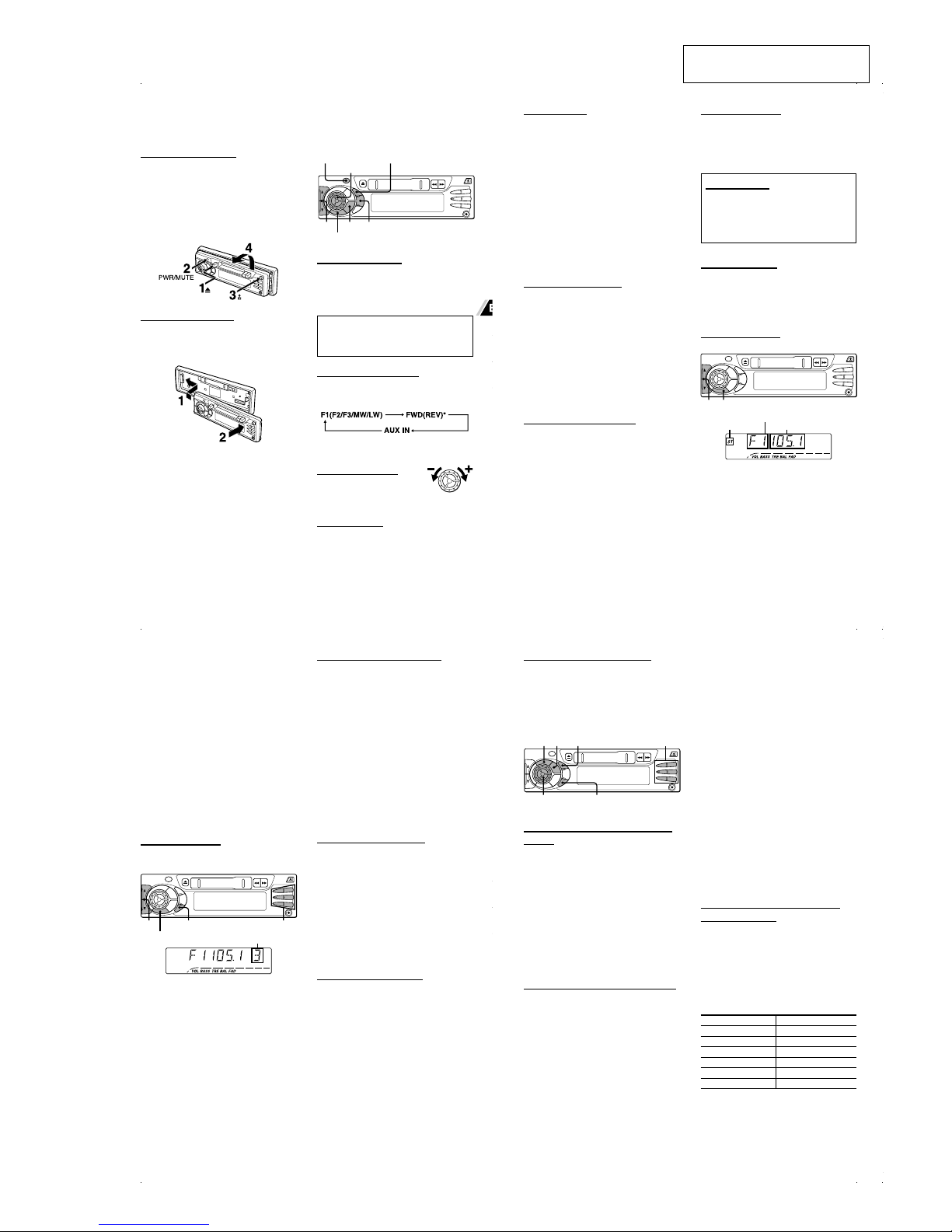
Precaution on making connections
Before connecting, make sure that the ignition switch is
set to OFF, and remove the earth terminal of the battery
to protect the unit and your car from damage.
Caution
Make the connections correctly, as illustrated in the
connection diagram.
Donot connectthe negative(cordof eachspeaker
wireto a common point. Whenreplacing thefuse, be
sure to use a fuse of the same rated amperage. Use
of a fuse of a higher rating may cause serious
damage to the unit.
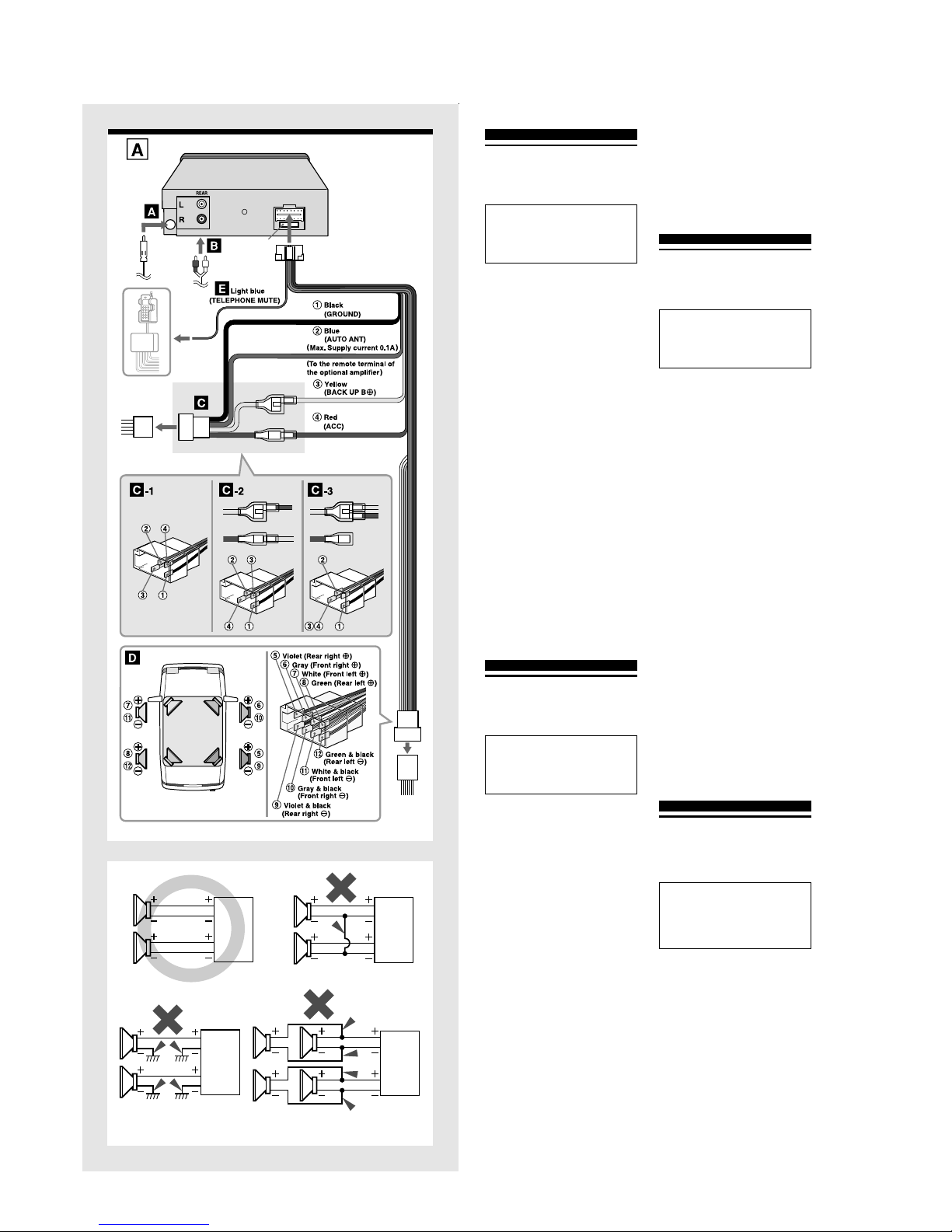
CONNECTION DIAGRAM →A
AFrom the car antenna
BTo the input jack of the optional power
amplifier (for the rear channel)
C
TotheISOconnectorofthe vehicle(powersupply)
Make sure the pin arrangement of the power-supply
connector of your car conforms to that of the standard
ISO connector C-1.
Some car types may have a different pin arrangement,
C-2or C-3.In that case, change theconnections ofthe
red and yellow leads as shown in C-2 or C-3.
Note
If your car is not prefitted with ISO standard connectors,
youshould usean adaptoravailable fromyour retaileror
any good automotive accessory shop.
Colors of leads
1
Black (ground lead to be connected to vehicle [metal] body.)
2Blue (power antenna lead to be connected to the
terminal of the control relay switch for a vehicle
equipped with a fully automatic power antenna. This
lead is not used for a vehicle with a manual antenna
or a switch-operated power antenna. If you will use
theoptionalpoweramplifierwiththeunit,connectthis
lead to the remote terminal of the amplifier.)
(Max. supply current 0.1 A)
3Yellow (battery lead to be connected to the backup
terminal from which power is always supplied.)
4
Red (ACC lead to be connected to the terminal from which
power is supplied when the ignition switch is set to ACC.)
DTotheISOconnectorofthevehicle(speaker
connection)
Colors of leads
5/9
Violet/Violet & Black; Rear right )/(
6/0Gray/Gray & Black; Front right
)/
(
7/!White/White & Black; Front left
)/
(
8/@Green/Green & Black; Rear left
)/
(
Notes
•Use speakers with an impedance of 4 to 8 ohms and
with adequate power-handling capacities. Otherwise,
the speakers may be damaged.
•Do NOT connect the speakers in parallel.
•DoNOTconnectthe terminalsofthespeakersystem to
the car chassis.
ETotheradiomuteleadofthecellularphone
hands-free car kit, etc.
Whenthe telephonemutelead (lightblue) isconnected to
acellularphone hands-freecarkit, etc.,theunit mutesthe
sound from the speakers automatically during your
conversationonthecellularphone.Fordetails,refertothe
instructionmanual for thecellular phonehand-freecar kit.
Note
Thistelephonemuteleadsupportsconnectiononlytothe
radio mute line. When connected to another type of
output system, it will not work.
ESPAÑOL
CONEXIONES
PRECAUCIONES
Precauciones al hacer las conexiones
Antesdeconectar,confirmequeelinterruptordeencendido
está en OFF y desmonte el terminal a tierra de la batería
para proteger el aparato y su coche contra daños.
Precaución
Haga las conexiones correctamente, tal como se
describe en el diagrama de conexiones.
No conecte el cable negativo
(
de cada cable de altavoz
aunpuntocomún.Cuandocambieelfusible,utilicesiempre
uno del mismo amperaje nominal. El uso de un fusible de
mayor régimen puede provocar daños importantes en el
aparato.
DIAGRAMA DE CONEXIONES →A
ADe la antena del coche
BA la toma de entrada del amplificador de
potencia opcional (para el canal trasero)
CAlconectorISOdel vehículo(alimentación
eléctrica)
Compruebe que la forma de patillas del conector de
alimentación eléctrica de su coche es un conector que
cumpla con la norma ISO C-1.
Algunos tipos de coche pueden tener otra forma de patillas
diferente,
C
-2 o
C
-3. En este caso, cambie las conexiones
de los cables rojo y amarillo como se indican en
C
-2 o
C
-3.
Nota
Si su coche no tiene conectores que cumplan la norma ISO,
debeutilizarunadaptadordeventaensudistribuidorocualquier
tienda de accesorios para automóviles completa.
Colores de los cables
1Negro (cable a tierra a conectar a la carrocería del
vehículo [metal].)
2
Azul (cable de antena motriz a conectar al terminal del
interruptor del relé de control para un vehículo equipado
con antena motriz totalmente automática. Este cable no
se debe utilizar en un vehículo con antena manual o
antena motriz que funcione mediante interruptor. Si
utilizaelamplificadordepotenciaopcionalenestaunidad.
conecte este cable al terminal remoto del amplificador.)
(Corriente máxima 0,1 A)
3Amarillo (cable de batería a conectar al terminal de
reserva con un flujo permanente de electricidad.)
4
Rojo(cableACCaconectaralterminalquerecibeeléctrica
cuando el interruptor de encendido está en ACC.)
DAl conector ISO del vehículo (conexión de
altavoces)
Colores de los cables
5/9Violeta/Violetaynegro;parteposteriorderecha)/(
6/0Gris/Gris y negro; parte frontal derecha )/(
7/!Blanco/Blanco y negro; parte frontal izquierda )/(
8/@Verde/Verde y negro; parte posterior izquierda )/(
Notas
•Utilice altavoces con una impedancia de 4 a 8 ohmios
y con suficiente capacidad eléctrica. De lo contrario
puede dañar los altavoces.
•NO conecte los altavoces en paralelo.
•NO conecte los terminales del sistema de altavoces al
chasis del coche.
L
R
R
L
L
R
L
R
EAl conductor de silenciamiento de radio
del kit de manos libres para el teléfono
celular de coche, etc.
Cuandoelcabledesilenciamiento(marrón)parateléfono
está conectado al kit de manos libres para teléfono
celulardecoche,etc.,launidadsilenciaautomáticamente
los altavoces durante su conversación en el teléfono
celular. Para más detalles, consulte el anual de
instruccionesdelkitdemanoslibresparateléfonocelular
de coche.
Nota
Este cable de silenciamiento de teléfono sólo puede
conectarse a la línea de silenciamiento de radio. No
funcionará si lo conecta a otro tipo de sistema de salida.
FRANÇAIS
CONNEXIONS
PRECAUTIONS
Précautions pour les connexions
Avantle raccordement,vérifiezque laclé d’allumage est
sur OFF, et débranchez la prise de terre de la batterie
pour protéger l’appareil et votre voiture des dommages.
Attention
Effectuez les connexions correctement, comme
indiqué sur le diagramme de connexion.
Ne raccordez pas le cordon négatif (de chaque fil
dehaut-parleuràunpointcommun.Auremplacement
du fusible, utilisez un fusible à ampérage nominal
identique. L’emploi d’un fusible à ampérage plus
élevé peut sérieusement endommager l’appareil.
DIAGRAMME DE CONNEXION →A
ADe l’antenne du véhicule
BA la prise d’entrée de l’amplificateur de
puissanceenoption (pour le canalarrière)
C
AuconnecteurISOduvéhicule(alimentation)
Vérifiez que l’agencement des broches du connecteur
d’alimentation du véhicule est conforme à celle du
connecteur ISO standard C-1.
Certainstypesdevoiturepeuventavoirunagencementdebroches
différent,
C
-2ou
C
-3.Dans ce cas,modifiez lesconnexions des
fils rouge et jaune comme indiqué en
C
-2 ou
C
-3.
Remarque
Si votre voiture n’est pas dotée d’un connecteur standard
ISO,utilisez un adaptateurdisponiblechez votrerevendeur
ou dans tout bon magasin d’accessoires automobiles.
Couleurs des fils
1Noir(filde miseàla terre àraccorderà lacarrosserie
[métal] du véhicule.)
2Bleu(fild’antenneélectriqueàraccorderàlaprisedu
commutateurderelaisdecommandepourunvéhicule
équipé d’une antenne électrique entièrement
automatique. Ce fil n’est pas utilisé sur les véhicules
à antenne manuelle ou antenne électrique opérée
par commutateur. Si vous souhaitez utiliser
l’amplificateur de puissance en option avec cet
appareil,raccordez ce filà laprisede télécommande
de l’amplificateur.)
(Courant d’alimentation maxi. 0,1 A)
3Jaune(fildebatterieàraccorderàlaprisedesecours
de laquelle l’alimentation se fait toujours.)
4Rouge (fil ACC à raccorder à la prise à partir de
laquelle la puissance est fournie quand la clé
d’allumage est réglée sur ACC.)
DAu connecteur ISO du véhicule
(raccordement des enceintes)
Couleurs des fils
5/9Violet/Violet et Noir; Arrière droite
)/(
6/0Gris/Gris et Noir; Avant droite
)/(
7/!Blanc/Blanc et Noir; Avant gauche
)/(
8/@Vert/Vert et Noir; Arrière gauche
)/(
Remarques
•Utilisez des enceintes à impédance de 4 à 8 ohms et
puissance nominale adéquate. Sinon elles seront
endommagées.
•Ne raccordez PAS les enceintes en parallèle.
•Ne raccordez PAS les prises du système d’enceintes
au châssis de la voiture.
EAu conducteur d’assourdissement radio
dukittéléphonecellulaireautomainslibres
Quandleconducteurd’assourdissementradio(bleuciel)
est relié à un kit téléphone cellulaire auto mains libres,
etc., l’appareil assourdit automatiquement le son des
enceintespendantlaconversationautéléphonecellulaire.
Pour les détails, consultez le mode d’emploi du kit
téléphone cellulaire auto mains libres.
Remarque
Le fil d’assourdisseur pour téléphone automobile peut
seulementêtreraccordéàlaligned’assourdisseurradio.
Il sera sans effet s’il est raccordé à un autre type de
système de sortie.
DEUTSCH
ANSCHLÜSSE
VORSICHTSMASSREGELN
Vorsichtsmaßregel zur Herstellung von Anschlüssen
Vor dem Herstellen von Anschlüssen sicherstellen, daß
der Zündschalter auf OFF steht und die Masseklemme
der Batterie entfernen, um das Gerät und das Fahrzeug
vor Schäden zu schützen.
Vorsicht
Die Verbindungen korrekt herstellen, wie im
Anschlußdiagramm gezeigt.
Nicht die negative (Leitung jedes
Lautsprecherkabels an einen gemeinsamen Punkt
anschließen.BeimAustauschenderSicherungimmer
eine Sicherung der gleichen Stärke verwenden.
Verwendung einer höheren Sicherung kann zu
schweren Schäden am Gerät führen.
ANSCHLUSSDIAGRAMM →A
AVon der Autoantenne
BVerstärkerendstufe (für hinteren Kanal)
CZum ISO-Anschluß des Fahrzeug
(Betriebsstromversorgung)
Stellen Sie sicher, daß die Pinanordnung der
BetriebsstrombuchsedesFahrzeugsderStandard-ISO-
Buchse C-1 entspricht.
Bestimmte Fahrzeugtypen können eine andere
Pinanordnung haben, C-2 oder C-3. In diesem Fall
ändern Sie die Verbindungen der roten und gelben
Leitungen wie in C-2 oder C-3 gezeigt.
Hinweis
Wenn Ihr Fahrzeug nicht bereits mit ISO-
Standardbuchsen ausgestattet ist, sollten Sie einen
Adapter verwenden, der von Ihrem Fachhändler oder
einem guten Automobilzubehörgeschäft erhältlich ist.
Leitungsfarben
1Schwarz (Masseleitung zum Anschluß an die
Fahrzeugkarosserie [Metall].)
2
Blau(MotorantennenleitungzumAnschlußandieKlemme
des Relaisschalters für ein Fahrzeug, das mit
vollautomatischer Motorantenne ausgestattet ist. Diese
Leitung wird nicht für ein Fahrzeug mit manueller Antenne
oder einer schalterbetriebenen Motorantenne verwendet.
Wenn Sie die optionale Verstärkerendstufe mit dem Gerät
verwenden wollen, diese Leitung an die
Fernbedienungsklemme des Verstärker anschließen.)
(Max. Versorgungsstrom 0,1 A)

CT-R442
7
SET
2-3. SUB PANEL ASSY
(Page 9)
FRONT PANEL SECTION
(Note: Illustration of disassembly is omitted.)
2-2. MECHANICAL DECK ASSY
(CDS-363AG1-A)
(Page 8)
2-4. MAIN BOARD
(Page 10)
SECTION 2
DISASSEMBLY
• This set can be disassembled in the order shown below.
2-1. DISASSEMBLY FLOW

CT-R442
8
Note: Follow the disassembly procedure in the numerical order given.
2-2. MECHANICAL DECK ASSY (CDS-363AG1-A)
1
screw
(PTT2.6
×
4)
2
cover
4
two screws
(PTT2.6
×
6)
9
mechanical deck assy
(CDS-363AG1-A)
5
connector
(CN202)
6
connector
(CN201)
7
two convexes
8
3
two screws
(PTT2.6
×
6)

CT-R442
9
2-3. SUB PANEL ASSY
1
screw
(PTT2.6
×
4)
2
cover
3
screw
(PTT2.6
×
4)
5
insulation sheet
4
cover
6
two screws
(PTT2.6
×
6)
8
sub panel assy
7
two claws
7
two claws

CT-R442
10
2-4. MAIN BOARD
1
two screws
(PTT2.6
×
6)
3
connector
(CN201)
4
convex
4
convex
2
connector
(CN202)
7
main board
5
6
mechanical deck assy
(CDS-363AG1-A)

11
CT-R442
SECTION 3
ELECTRICAL ADJUSTMENT
FM RDS S-METER ADJUSTMENT
Setting:
Procedure:
1. Press the [TUNER TU] button to set “FM”.
2. Adjust RV101 on MAIN board so that the value of digital
voltmeter becomes 2.0 ±0.1V.
set
MAIN board
FM/AM antenna
(J101)
FM RF signal
generator
Carrier frequency : 98.00 MHz
Output level : 31 dB (35.5 µV)
Mode : mono
Modulation : 1 kHz , 45 kHz deviation
0.01 µF
digital voltmete
r
100 k
Ω
MAIN board
TP (S.METER) +
–
Adjustment Location:
– MAIN BOARD (Component Side) –
RV101
FM RDS S-meter
Adjustment
– MAIN BOARD (Conductor Side) –
TP
(S.METER)
IC901

12
CT-R442 SECTION 4
DIAGRAMS
Note on Schematic Diagram:
•All capacitors are in µF unless otherwise noted. pF: µµF
50 WV or less are not indicated except for electrolytics
and tantalums.
•All resistors are in Ωand 1/4W or less unless otherwise
specified.
•C: panel designation.
•A: B+ Line.
•H: adjustment for repair.
•Powervoltageis dc14.4Vand fedwithregulateddc power
supply from ACC and BATT cords.
•Voltages and waveforms are dc with respect to ground
under no-signal (detuned) conditions.
no mark : FM
():MW
[]:LW
〈〈 〉〉 : TAPE PLAYBACK
•Voltagesare takenwith aVOM (Inputimpedance10 MΩ).
Voltage variations may be noted due to normal produc-
tion tolerances.
•Waveforms are taken with a oscilloscope.
Voltage variations may be noted due to normal produc-
tion tolerances.
•Circled numbers refer to waveforms.
•Signal path.
F: FM
f: AM (MW/LW)
E: TAPE PLAYBACK
a: AUX IN
Note on PrintedWiring Board:
•X: parts extracted from the component side.
•Y: parts extracted from the conductor side.
•W: indicates side identified with part number.
•: Pattern from the side which enables seeing.
(The other layers' patterns are not indicated.)
Caution:
Pattern face side: Partsonthepatternfaceside seenfrom
(Conductor Side) the pattern face are indicated.
Parts face side: Parts on the parts face side seen from
(Component Side) the parts face are indicated.
4-1. NOTE FOR PRINTED WIRING BOARDS AND SCHEMATIC DIAGRAMS
C
BThese are omitted.
E
Q
•Indication of transistor.

CT-R442
1313
JW101
JW104
JW106
JW108
JW109
JW110
JW105
JW111
JW112
JW116
JW117
JW120
JW123
JW124
JW125
JW129
JW130
JW131
JW132
JW134
JW136
JW137
JW138
JW139
JW140
JW146
JW147
JW148
JW149
JW156
JW157
JW158
JW159
JW162
JW166
JW168
JW176
JW196
JW198
JW209
JW210
JW211
JW213
JW218
JW219
JW220
JW223
JW224
JW228
JW230
JW233
JW237
JW241
JW243
JW246
JW248 JW249
JW250
JW102
JW240
JW244
JW242
JW245
L102
L101
D101
D102
R104
R102
R116
R101
R121
R122
R103
C106
C104
C116
C153
D151
L901
R706
R707
R708
R903
R912
R913
C904
CN202
R212
R215
C203
C204
C209
C210
R211
C409
C410
C420
C401
C402
C415 C417
R406
R408
R415
R416
R417
R418
R430
R421
R424
IC501
D501
D502
C510
R509
R510
R501
R502
R503
R504
R523
R524
R525
R526
R521
CN701
R701
R702
D802
R803
R809
R808
L801
R806
C701
C702
Q801
Q803
CN201
D503
D504
D505
D506
D507
D508
R914
JW167
R923
R922
R921
R924
JW200
R902
JW222
R214
JW188
JW199
JW180
JW185
JW173
JW113
JW119
JW163
JW178
JW216
JW208
JW184
JW181
JW207
JW191
JW186
R428
R427
R426
R216
R709
R705
L701
JW171
JW254
Q804
IC201
JW234
D906
Q201
JW192
JW255
JW256
X151
CN802
JW172
JW161
C511
C509
C901
D808
JW203
JW103
JW150
JW239
JW225
JW170
JW143
JW128
JW221
JW226
C416
JW189
JW190
JW133
JW215
JW182
JW142
C433
JW238
D810
THP802
D811
R810
RV101
JW217
C432
X901
D801
JW107
R451
R152
R213
R805
R804
D902
D509
D403
D804
D806
D807
D803
C431
C205
C211
C206
C426
C903
C805
C213
C419
C418
JW206
C513
R429
C424
C165
C118
R905
C804
R807
R915
Q101
Q102
Q103
C101
C102
C103
C114
R108
R109
R110
R111
R115
C108
C121
C122
R114
R119
C110
R107
C111
R106
C113
C105
C123
C124
R124
R151
R712
R710
R711
C151
C152
C154
R908
C155
C156
C109
R105
R123
C119
Q105 Q106 Q107
R112
C115
C117
R118
C514
R704
R201
R202
C201
C202
R205
R207
C207
R209
R210
C208
R208
R206
C501
C502
C503
C504
C505
C506 C507
C508
R505
R506
R507
R508
C512
R511 Q501
C434
C435
C802
C803 R801
Q404
Q405 Q406
Q407
Q408
R405
R407
R403
C425
Q807
Q808
Q802
C806
R217
C902
C430
R425
C801
C411
C412
C413
C414
Q403
C429
R419
R420
R422
R404
C404
R423
C408C907
C908
C909
C910
C914
C915
IC401
R203
R204
C212
IC151
C423
C407
C405
C403
R401
R930
R925
R926
R927 R928
R929
IC901
D402
R904
R910
R909
R933
R402
C406
Q410
R113
D705
D510
C704
R917
R916
JC116
JC101
JC103
JC104
JC105
JC106
JC108
JC109
JC110
JC111
JC113
JC115
JC121
JC122
JC123
JC124
JC125
JC126
JC127
JC128
JC129
JC256
JC258
JC259
Q202
R703
C703
R936
D721
D720
S901
(RESET)
D704
D703
D702
D701
C520
C522
C521
C427
C428
C911
JC262
Q108
Q411
R522
R906
R433
R920
2
125
24
44
1
11 12
23
3334
31
8
1
MECHANISM
BLOCK
E
C
B
E
E
E
E
E
E
EEE
E
E
KA
K/A
EE
EE
A
K
A
E
E
E
E
K
AA
1
3031
50
51
80 81
100
1
8
16
9
1
2
15
14
A
KEY BOARD
CN601
TU101
(TUNER UNIT)
1
26
1
8
MAIN BOARD
J101
(FM/AM ANTENNA)
REAR
L R
J401
16
8
9
1
1817
19
F801
1 9 WHT/BLK
GRN/BLK
VIO/BLK
GRY/BLK
LIGHT BLU
YEL
WHT
GRN
VIO
GRY
BLU
RED
BLK
2 10
3 11
4 12
5 13
6 14
7 15
8 16
RL+ RL– GRN/BLK
WHT/BLK
GRY/BLK
VIO/BLK
GRN
WHT
GRY
VIO
FL+ FL–
FR+ FR–
RR+ RR–
ACC GND BLK
YEL
RED
BLU
ANT REM NC BATT
NC NC
ATT
TO
CN802
NC
E
C
B
E
C
B
1-687-799- 12
+
B
C
E
(CHASSIS)
(CHASSIS)
1 2 3 4 5 6 7 8 9 10 11 12 13 14 15 16
A
B
C
D
E
F
G
H
I
J
K
L
M
22
TP
(S. METER)
E
4-2. PRINTED WIRING BOARD – MAIN Board –
D101 D-2
D102 D-2
D151 I-4
D402 I-9
D403 E-8
D501 D-10
D502 D-10
D503 D-11
D504 D-11
D505 D-12
D506 D-12
D507 D-11
D508 D-11
D509 C-5
D510 D-5
D701 K-3
D702 K-3
D703 K-3
D704 K-3
D705 M-5
D720 L-5
D721 L-5
D801 C-14
D802 G-12
D803 G-14
D804 I-13
D806 I-14
D807 H-13
D808 K-12
D810 D-12
D811 D-13
D902 J-13
D906 K-6
IC151 J-5
IC201 F-3
IC401 H-10
IC501 B-6
IC901 J-8
Q101 F-2
Q102 G-2
Q103 G-2
Q105 H-5
Q106 H-5
Q107 H-6
Q108 H-6
Q201 J-14
Q202 K-14
Q403 H-9
Q404 F-10
Q405 F-9
Q406 F-11
Q407 F-10
Q408 E-10
Q410 F-8
Q411 H-8
Q501 C-4
Q801 E-15
Q802 G-13
Q803 F-15
Q804 H-14
Q807 H-13
Q808 I-13
•Semiconductor
Location
Ref. No. Location
(Page 18)

CT-R442
1414
R206
R205
C102
CN202
R106 C113
R103
C122
C121
R104
C111
C108
R108
C124
R122
R111
R112 C116
R109 C115
C114R102
C110
R105C109
R101 L101
C101
D101
D102
C204
C202 R202
C203
C205R203 C206 R204
C208 R208R207 C207 C211 C212
R211
C210
R210
R209 C209
R212
R217 R214
C201 R201
CN201
J101
Q106 Q105
IC201
R107
R213
C105R116 C106
R110
Q103Q102
C103
C213
L102
C104
TU101
JC101
JC108
JC122
JC124
JC109
JC258
JC116
Q201
Q202
R215R216
Q101
RV101
R124
R123 R113
C119
R121
C123
R115R114
R119
R118 C118
C117
JC259
IC151
C154 C155
R152
Q107
Q108
C153 D151 C156
R151
X151
C152C151
TP
5.6k
5.6k
0.01
8P
33k 0.1
180
18000p
18000p
10
0.01
0.047
10k
0.47
6.8k
10
820 2.2
50V
2.2k 0.01
0.0221k
0.1
47k0.01
1M
100p
1SS133T
1SS133T
10
16V1000p 220k
10
16V
33
50V
39 33
50V
39
0.022 150k150k 0.022 100
10V 0.1
47
1
50V1k
1k 1
50V
4.7k
100k 1k
1000p 220k
3P
MSD601
-RT1 MSD601
-RT1
LA3161
47k
4.7k
0.0221k 47
16V
33
MSD601
-RT1
MSB709
-RT1
4700p
47
16V
22
25V
FAE347-E40
0
0
0
0
0
0
0
DTB123YS
MUN2211T1
47k47k
MUN2211T1
220k
100k
47k 0
0.01
6.8k
0.47
10k10k
4.7k
1k 0.1
50V
4700p
0
SAA6579T
330p 560p
330
MSD601-RT1
MSD601-RT1
2.2
50V MTZJ5.1B 0.1
2.2k
4.332MHz
27p30p
(S.METER)
A1
A2
B1
RA-R
RA-L
TA-R
TA-L
VS2
VS2
VS1(14V)
A79
A86
A88
A87
A54
A44
A31
A39
A41
A48
A21
A62
A64
A58
A51
A47
(1/3)
(TUNER UNIT)
(FM/AM ANTENNA)
AM B+
SWITCH SWITCH
FM B+
LOCAL/DX
SWITCHING
Q105,106
LOW-PASS
FILTER
INPUT
NF
OUTPUT
VCC
GND
OUTPUT
NF
INPUT
TAPE PRE AMP
CAPSTAN/REEL
MOTOR DRIVE
Q201,202
MECHANISM
BLOCK
DUAL
DATA
VREF
MUX
VDD
GND
CIN
SCOUT
MODE
CL
T57
XOUT
XIN
VDD
GND
TEST
RDS DECODER
Q107,108
FILTER
LOW-PASS
4.7µH
4-3. SCHEMATIC DIAGRAM – MAIN Board (1/3) – • See page 17 for waveform. •See page 17 for IC Block Diagrams.
(Page 15)
(Page 16)

CT-R442
1515
R418
R416
CN701
L701
R701
R702
C701
C423
R703R704
C702
R705
R706
R707
R708
R709
R710
R711
D705
R417
C409
C407
C405
R401
C403
C401
R426
R427
R428
R429
Q410
R430
D403
C417
C425
R405
R407
C416
C414C412
R404
C410
C408
C406
R402
C404
C402
R408
C420
R403
C413C411
C415
R406
Q408
Q404 Q406
Q405 Q407
R415
IC401
R451
C703
C704
C424
C419
C426
C418
D721
D720
JC113
JC115
JC256
JC127
JC106
JC105
D704
R712
D701
D702
D703
JC121
C431
Q411
1k
1k
15P
4.7k
4.7k
1
50V
0.022
5.6k5.6k
1
50V
1k
1k
1k
1k
1k
10k
10k
DAN202K
1k
10
16V
0.022
3300p
3.3k
1
1
50V
1k
1k
1k
2.2k
DTC114TKA
10k
1SS133T
4.7
35V
0.1
1k
1k
10
16V
0.150.15
3.3k
10
16V
0.022
3300p
3.3k
1
1
50V
1k
4.7
35V
3.3k
0.150.15
10
16V
1k
DTA114TK
DTC114TK DTC114TK
DTC114TK DTC114TK
1k
LC75374E
100
1000p
1000p
100
10V
4.7
50V
22
25V
4.7
50V
MM3Z6V8ST1
MM3Z6V8ST1
0
0
0
0
0
0
MTZJ6.8C
100k
MTZJ6.8C
MTZJ6.8C
MTZJ6.8C
0
1
50V
MUN211T1
A1
A2
C1
C2
C3
C4
C5
C6
C7
VS1(14V)
A20
A19
A18
VS2
LEV-L
RA-L
TA-L
TA-R
RA-R
LEV-R
AUX-L
AUX-R
AUX-R
LAMP B+
A02
A06
A04
A03
A05
A80
A81
VS4
AUX-L
A68
AUX GND
AUX-L
AUX-R
N.C
LAMP B+
DFP IN
N.C
LCD CE
LCD DO
LCD DI
LCD CLO
RE1
RE2
VDD
GND
(2/3)
MUTINGMUTING
MUTINGMUTING
SWITCH
MUTING CONTROL
INPUT SELECT SWITCH,
ELECTRICAL VOLUME
Q408,410,411
4.7µH
4-4. SCHEMATIC DIAGRAM – MAIN Board (2/3) – • See page 17 for IC Block Diagram.
(Page 14)
(Page 16)
(Page 19)

CT-R442
1616
C508
D501
D502
D505
D507
D503
D504
D508
D506
C434
C435
J401
C511
R510
R509
R505
R506
R507
R508
C505
C506
C507
C501
C502
C503
C504
C514
R521
R422
R420 C428
R419
C427R421
C429R424
D402
R425
TP4
TP3
TP2
TP5
R902 R916 R917 R929R915
R924
R921
R922
R923
R914
D902
R504
R502
R503
R501
R525
R524
R523
C902 C903
C430
R933
R925
R926
R927
R928
R912
R913
C901
R910
R909
R908
R930
C512 C513
D810
R936
R920
D803
C804
D802
R807
C805
C806
D808
R808
R805
R806
R804
D811 C803
R801
D801 C801 C802
L901
R904
TP1
TP6TP7
C910
C914
C915
C908
X901
C907
D804
D806D807
R511
IC501
CN802
L801
THP802
Q801
Q803
R803
Q804
R423
Q403
S901
D509
C909
R903
Q501
D510
C432
C433
C509
C510
R809
R810
C521
C522
C520
JC123
Q807
Q808
Q802
JC128
JC129
JC111
F801
R906
C911
R905
JC262
D906
IC901
C165
C904
R522 R526
R433
820p
1N4002
1N4002
1N4002
1N4002
1N4002
1N4002
1N4002
1N4002
470p
470p
2P
0.1
50V
1k
2.2k
18k
18k
18k
18k
820p
820p
820p
0.47
0.47
0.47
0.47
2200p
1k
1M
100k 0.1
100k
0.14.7k
0.110k
DAN217
1M
100k 100k 100k 100k2.2k
2.2k
2.2k
2.2k
2.2k
47k
MTZJ-T-77-5.1B
12k
12k
12k
12k
100k
100k
100k
0.022 100
10V
0.01
22k
100k
100k
100k
100k
47k
47k
0.1
50V
100k
100k
100k
100k
0.1 2200
16V
1N4002
47k
47k
MTZJ10B
220
16V
MTZJ6.8C
100k
47
16V
0.022
1SS133T
68
2.2
1/2W
470
680
1/2W
1N4002 0.1
22k
1N5402 0.1 2200p
0
1000p
100p
100p
10p
6.3MHz
10p
MTZJ-T-77-5.1B
MTZJ6.2AMTZJ6.8C
22k
TA8252H
16P
2SB1375
2SD2012
10k
2SD1858
1k
MSD601-RT1
MTZJ6.8C
0.1
47k
DTA114TK
DAN202K
10
50V
10
50V
10
50V
22
25V
6.8k
4.7k
100p
100p
100p
0
MUN2211T1
MUN2113T1
MUN2211T1
0
0
0
10A
32V
1k
0.01
1k
0
1SS133
-3BA
0.1
0.022F
5.5V
2.7k 100k
10k
B1
C6
C5
C4
C3
C2
C1
C7
A59
LEV-R
LEV-L
VS2
VS3
PHONEMUTE
A59
A01
A02
A03
A04
A05
A06
A18
A19
A20
A21
A31
A39
A41
A44
A48
A54
A56
A57
A62
A65
A67
A68
A79
A80
A81
A86
A87
A88
A01
5VBU
FL+
FL+
FL-
FL-
RL-
RL-
RL+
RL+
RR+
RR+
RR-
RR-
FR-
FR-
FR+
FR+
VS3
VS4
A52
LAMPB+
VS2
VS1(14V)
A52
A56
A65
PHONE MUTE
A57
A67
RL-
RL-
FL-
FL-
FR-
FR-
RR-
RR-
RL+
RL+
FL+
FL+
FR+
FR+
RR+
RR+
GND
GND
BATT
BATT
ACC
ACC
ANT REM
ANT REM
A47
A51
A58
A64
POWER AMP
ACC
GND
BATT
L
R
FM/AM S METER
AVSS
REGCPU
VDD
CDS CS
CDS SLEEP
CDS RESET
CDS IN
SEN 2
SEN 1
MF CONT
FLAP IN
MAIN M CONT
REEL
STANDBY
PANCON2
PANCON1
NC
GND
RE2 IN
NC
NC
TEST
AVDD
NC
AUTO VOL
LEVEL IND
DSSA CONT
LOC/DX
EVOL DO
EVOL CLO
CD CLO
BBE 2
CD CONECT
CD DISP SEL
CD CLI
CD DO
CD DI
CDS CLO
CDS DI
BBE 1
LCD CE
LCD CLO
LCD DO
LCD DI
DFP IN
BATT IN
CDS DO
RDS CLK IN
ACC IN
RMT IN
ST-IND/SD IN
NC
POWER CONT
RDS DI
BEEP
NC
NC
BAND CONT
CD ACC CONT
RDS MODE
LCD CONT2
LCD CONT1
AF MUTE
NC
NC
MI-1
MI-2
MI-3
MO-1
MO-2
MO-3
MO-4
AUX IN
PACK IN
RE1 IN
GND
VDDPORT
CDS STOP
RADIO CONT
EO O
EO I
IC
REGOSC
X2
X1
GND
IF REQ
GND
AM IF
FM IF
VDD PLL
FM OSC
AM OSC
GND PLL
(3/3)
PRE-GND
STBY
MUTE
TAB VCC2 VCC1
GND3
GND1
GND2
GND4
CLIP OUT&
OUT
DIAGNOSIS
FL+
FL-
RL+
RL-
RR+
RR-
FR+
FR-
AMP REM
ATT
ILL
TEST
ATT
REAR
BATTERY OFF
MUTING DRIVER
POWER ON/OFF
CONTROL SWITCH
B+ SWITCH
+10V REGULATOR
Q807,808
ACCESSORY
CHECK
+5.6V REGULATOR
SYSTEM CONTROLLER
EVOL CE
NOISE LEVEL
DETECT
(RESET)
ANT REM
RIP
RESET
ST-BY MUTE
POWER MUTE
PHONE MUTE
370µH
µPD178078GF-565
47µH
4-5. SCHEMATIC DIAGRAM – MAIN Board (3/3) – • See page 17 forWaveform.
(Page 14)
(Page 15)

CT-R442
1717
•IC Block Diagrams
– MAIN Board –
IC151 SAA6579T
IC401 LC75374E
INPUT
NF
VCC
OUTPUT
INPUT
GND
OUTPUT
NF
8
7
6
5
4321
CONSTANT
VOLTAGE
CIRCUIT
AMP1 AMP2
+
–
+
–
+
–
+
–
+
–
+
–
+
–
+
–
+
–
+
–
+
–
+
–
+
–
+
–
DECODER LATCH SHIFT
REGISTER
CONTROL
–
+
+
–
12 3 45 6 7 8 9 10
20
19
18
17
16
15
14
13
12
11
21
22
2324252627282930313233
34
35
36
37
38
39
40
41
42
43
44
LSELO
L4
L3
L2
L1
VDD
R1
R2
R3
R4
RSELO
RVRIN
RCOM
RT1
RT2
RT3
RTOUT
RSIN
NC
NC
RSB1
RSB2
RFIN
RFOUT
RROUT
VSS
CL
DI
CE
VREF
LROUT
LFOUT
LFIN
LSB2
LSB1
NC
NC
LSIN
LTOUT
LT3
LT2
LT1
LCOM
LVRIN
1 2 3 4 5 6 7 8 9 10 11 12
21
22
23
24
25
26
27
28
29
30
31
32
333435363738394041
53
54
56
57
58
59
60
61
64
13 14 15 16
17
18
19
20
51
52
50
KI1
KI2
KI3
KI4
KI5
OSC
55
TEST
49
KS6
DO
62
CE
63
CL
DI
VDD
VDD1
VDD2
VSS
P1/S1
P2/S2
P3/S3
P4/S4
S5
S6
S7
S8
S9
S10
S11
S12
S13
S14
S15
S16
S39
S38
S37
S36
S35
S34
S33
4243
COM4
COM3
COM2
COM1
48 47 46 45 44
KS5
KS4
KS3
S41/KS2
S40/KS1
S32
S31
S30
S29
S28
S27
S26
S25
S24
S23
S22
S21
S20
S19
S18
S17
SEGMENT DRIVER & LATCH
SHIFT
REGISTER
COMMON
DRIVER
CLOCK
GENERATOR
CCB
INTERFACE
VDET
KEY BUFFER
CONTROL
REGISTER
KEY SCAN
– KEY Board –
IC601 LC75854W
•Waveforms
– MAIN Board –
1IC151 qf (XOUT)
3.6Vp-
p
159 ns
– KEY Board –
qa IC601 y; (OSC)
1.7 Vp-
p
22.8 µs
2IC901 eh (X2)
5.3 Vp-p
231 ns
IC201 LA3161
TEST LOGIC AND OUTPUT
SELECTOR SWITCH
QUALITY BIT
GENERATOR
OSCILLATOR
AND
DIVIDER
RECONSTRUCTION
FILTER
57KHz
BANDPASS
(8th ORDER)
ANTI-
ALIASING
FILTER
COSTAS LOOP
VARIABLE AND
FIXED DIVIDER
CLOCKED
COMPARATOR
CLOCK REGENERATION
AND SYNC
16 15 14 13 12 11 10 9
1 2 3 4 5 6 7 8
REFERENCE
VOLTAGE
DIFFERENTIAL
DECODER
BIPHASE
SYMBOL
DECODER
Vp1
QUAL
RDDA
VREF
MUX
VDDA
VSSA
CIN
SCOUT
RDCL
T57
OSCO
OSCI
VDDD
VSSD
TEST
TSTLD

CT-R442
1818
LED604
LED605
LED602
LED601
LED606
S603
S611
S606
S612
S602
S621
S616 S615
S604
S601
S608
S614
S605
S613
S609
CN601
Q603
C605
R602
R603
R604
R605
R601
R608
D601 D602
Q601
R616
R612
C601
R609
R611
C602
R610
C603
C604
R606
R607
C609
C610
R619
R618
R614
R624
R625
R613
R615
IC601
R617
S607
(COMPONENT SIDE)
KEY BOARD
1-687-805-
11
(11)
LED601, 602, 604 −606
(KEY ILLUMINATION)
K
A
S610
5
3
A
K
A
K
AK
A
K
A
K
1
16
17
3233
49
48
64
LCD601
LIQUID CRYSTAL DISPLAY
LED610
(LCD BACK LIGHT)
1
3
AUDIO CONTROL
S621
ROTARY ENCODER
PWR
MUTE
TUNER TU DSPL
LO SRC
SEL
EKK
A
KK
A
E
6
4
2
1
1-687-805-
11
(11)
(CONDUCTOR SIDE)
KEY BOARD
S601, 602,
S604 −609,
S611 −616
AUX BOARD
1-687-800-
11
(11)
BLK
BRN
RED
BLK
BRN
RED
AUX
J601
15 1
A
MAIN BOARD
CN701
14 2
PS
A. ME
1 2 3 4 5 6 7 8 9 10 11 12 13 14
A
B
C
D
E
F
G
H
I
141
TA
4-6. PRINTED WIRING BOARDS – KEY/AUX Boards –
LED604 C-1
LED605 D-3
LED606 C-13
LED610 G-5
Q601 G-10
Q603 G-5
Ref. No. LocationRef. No. Location
D601 G-10
D602 G-11
IC601 F-8
LED601 C-4
LED602 A-3
•Semiconductor Location
(Page 13)

CT-R442
1919
J601
C604
C603
C602
R612
C601
R611
R610
R609
TP4
TP1
TP2
TP3
R616
R625
Q601
Q603
R617
R618
R619
C605
LED610
R608
D601 D602
LED602
LED601
R624 R614
R613
R615
LCD601
IC601
R601
CN601
R607
S615
S612
S607
S611
S606
S604
S603
S605
S610
S614 S613
S609
S616
S602 S601
S608
R606
S621
C609
C610
R605
R604
R603
R602
LED604
LED605
LED606
0.047
0.047
0.047
68k
680p
4.7k
4.7k
4.7k
6.8k
6.8k
MSD601-RT1
MSD601-RT1
470
470
470
0.047
SLI-343YY3FW-ST
3.9k
STZ6.8N STZ6.8N
BR1112H-TR-RED
BR1112H-TR-RED
1k 330
470
1.5k
LC75854W
10k
15P
100k
100k
0.001
0.001
2.2k
2.2k
2.2k
2.2k
SML-012YTT86RST
SML-012YTT86RST
SML-012YTT86RST
S5
S6
S7
S8
S9
S10
S11
S12
S13
S14
S15
S16
S17
S18
S19
S20
S21
S22
S23
S24
S25
S26
S27
S28
S29
S30
S31
S32
S33
S34
S35
S36
S37
S38
S39
COM1
COM2
COM3
COM4
S44
S45
COM1
COM2
COM3
COM4
S5
S6
S7
S8
S9
S10
S11
S12
S13
S14
S15
S16
S17
S18
S19
S20
S21
S22
S23
S24
S25
S26
S27
S28
S29
S30
S31
S32
S33
S34
S35
S36
S37
S38
S39
S44
S45
AUX GND
GND
LCD DO
LCD DI
LCD CLO
VDD
LCD CE
RE1
RE2
COM4
COM3
COM2
COM1
S37
S36
S35
S34
S33
S32
S31
S30
S29
S28
S27
S26
S25
S24
S23
S22
S21
S20
S19
S18
S17
S16
S15
S14
S13
S12
S11
S10
S09
S08
S07
S06
S05
DFP IN
LAMP B+
S38
S39
S45
S44
S16
S15
S14
S13
S12
S11
S10
S9
S8
S7
S6
S5
P4/S4
P1/S1
P2/S2
P3/S3
S32
S31
S30
S29
S28
S27
S26
S25
S24
S23
S22
S21
S19
S18
S17
S20
KS6
KI1
KI2
KI3
KI4
KI5
TEST
VDD
VDD1
VDD2
VSS
OSC
DO
CE
CL
DI
S33
S34
S35
S36
S37
S38
S39
COM1
COM2
COM3
COM4
KS1
KS2
KS3
KS4
KS5
LIQUID CRYSTAL DISPLAY
(KEY ILLUMINATION)
LED601,602,604-606
(LCD BACK LIGHT)
N.C
N.C
AUX-R
AUX-L
AUX
KEY CONTROL
31
LED DRIVE
LED DRIVE
ROTARY ENCODER
AUDIO CONTROL
5
4
2
1
6
3SEL SRC
TA
LO
PWR
MUTE
DSPL
PS
A.ME
TUNER TU
LIQUID CRYSTAL DISPLAY DRIVER,
4-7. SCHEMATIC DIAGRAM – KEY/AUX Boards – • See page 17 forWaveform •See page 17 for IC Block Diagram.
(Page 15)

CT-R442
2020
•MAIN BOARD IC901 µPD178076GF-565-3BA (SYSTEM CONTROLLER)
Pin No. Pin Name I/O Description
1BATT IN I Battery voltage detection signal input terminal
2DFP IN I Front panel block remove/attach detection signal input terminal “H”: front panel is attached
3 LCD DI I Serial data input from the liquid crystal display driver
4 LCD DO O Serial data output to the liquid crystal display driver
5 LCD CLO O Serial data transfer clock signal output to the liquid crystal display driver
6 LCD CE O Chip enable signal output to the liquid crystal display driver
7 BBE 1 —Not used
8CDS DI I Not used
9CDS DO O Not used
10 CDS CLO O Not used
11 CD DI I Not used
12 CD DO O Not used
13 CD CLI I Not used
14 CD DISP SEL —Not used
15 CD CONNECT —Not used
16 BBE 2 —Not used
17 CD CLO O Not used
18 EVOL CLO O Serial data transfer clock signal output to the electrical volume
19 EVOL DO O Serial data output to the electrical volume
20 EVOL CE O Chip enable signal output to the electrical volume
21 LOC/DX O Local/DX selection signal output to the tuner unit “L”: DX, “H”: local
22 DSSA CONT —Not used
23 NC —Not used
24 PHONE MUTE I Telephone muting detection signal input terminal
At input of “L”, the audio signal is attenuated by –20 dB
25 LEVEL IND I Noise level detection signal input terminal
26 AUTO VOL —Not used
27 AVDD —Power supply terminal (+5V)
28 TEST —Not used
29, 30 NC —Not used
31 FM/AM S METER IFM and AM signal-meter voltage detection signal input from the tuner unit
32 AVSS —Ground terminal
33 REGCPU O Voltage regulator output terminal for the CPU
34 VDD —Power supply terminal (+5V)
35 REGOSC O Voltage regulator output terminal for the oscillator circuit
36 X2 O System clock output terminal (6.3 MHz)
37 X1 I System clock input terminal (6.3 MHz)
38 GND —Ground terminal
39 IF REQ O Intermediate frequency request signal output to the tuner unit
40 GND —Ground terminal
41 AM IF I AM intermediate frequency detection signal input from the tuner unit
42 FM IF I FM intermediate frequency detection signal input from the tuner unit
43 VDD PLL —Power supply terminal (+5V)
44 FM OSC I FM VCO input from the tuner unit
45 AM OSC I AM VCO input from the tuner unit
46 GND PLL —Ground terminal
4-8. IC PIN FUNCTION DESCRIPTION
Pin No. Pin Name I/O Description
47 EO O O PLL phase compartor output to the tuner unit
48 EO I O PLL phase compartor output to the tuner unit
49 IC —Connected to the ground
50 RESET I System reset signal input from the reset switch “L”: reset
For several hundreds msec. after the power supply rises, “L” is input, then it changes to “H”
51 RDS CLK IN I RDS serial data transfer clock signal input from the RDS decoder
52 ACC IN I Accessory power detection signal input terminal “H”: accessory power on
53 RMT IN I Not used
54 ST-IND/SD IN I FM stereo detection signal and station detector detection signal input from the tuner unit
55 NC —Not used
56 ST-BY MUTE O Standby on/off control signal output to the power amplifier
“L”: standby mode, “H”: amplifier on
57 POWER CONT O Power on/off control signal output terminal “H”: power on
58 RDS DI I RDS serial data input from the RDS decoder
59 BEEP O Beep sound drive signal output to the power amplifier
60, 61 NC —Not used
62 BAND CONT O FM/AM (MW/LW) band selection signal output terminal “L”: AM (MW/LW), “H”: FM
63 CD ACC CONT O Not used
64 RDS MODE O RDS mode select signal output to the tuner unit “H”: RDS mode
65 POWER MUTE O Muting on/off control signal output to the power amplifier “L”: muting on
66 LCD CONT2 O Power on/off control signal output for liquid crystal display driver “H”: power on Not used
67 LCD CONT1 O Power on/off control signal output for liquid crystal display driver “H”: power on
68 AF MUTE O Audio muting on/off control signal output terminal “H”: muting on
69, 70 NC —Not used
71 MI-1 I Diode matrix input terminal for initial setting Not used
72 MI-2 I Diode matrix input terminal for initial setting
73 MI-3 I Diode matrix input terminal for initial setting Not used
74, 75 MO-1, MO-2 O Diode matrix output terminal for initial setting Not used
76 MO-3 O Diode matrix output terminal for initial setting
77 MO-4 O Diode matrix output terminal for initial setting Not used
78 AUX IN I Not used
79 PACK IN I Tape in detection switch input terminal “H”: tape in
80 RE1 IN I Jog dial pulse input from the rotary encoder
81 RE2 IN I Jog dial pulse input from the rotary encoder
82 GND —Ground terminal
83 NC —Not used
84, 85 PANCON1,
PANCON2 —Not used
86 STANDBY I FF/REW detection switch input terminal “L”: FF/REW mode, “H”: playback mode
87 REEL I Tape direction switch input terminal “L”: reverse direction, “H”: forward direction
88 MAIN M CONT O Capstan/reel motor drive signal output terminal “H”: motor on
89 FLAP IN I Not used
90 MF CONT —Not used
91, 92 SEN 1, SEN 2 —Not used
93 CDS IN I Not used
94 CDS RESET —Not used
95 CDS SLEEP —Not used
Table of contents
Other Aiwa Car Receiver manuals
Popular Car Receiver manuals by other brands

JVC
JVC KD-SV3204 Installation & connection manual

Panasonic
Panasonic CQ1000EU - AUTO CASS/ RECEVIER operating instructions

Boss Audio Systems
Boss Audio Systems BV9371BD user manual

Audiovox
Audiovox AVDBR1 owner's manual

Sony
Sony CDX-R35MR operating instructions

Soundstream
Soundstream VR-450 owner's manual