Aiwa ADC-M60 User manual

dlri’m$
DIGITAL AUDIO
ADC-M60Y”
COMPACT DISC CHANGER
CAMBIADOR DE DISCOS COMPACTOS
OWNER’S RECORD
For your convenience, record the model number
and serial number (you will find them on the rear of
your set) in the space provided below. Please refer
to them when you contact your AIWA dealer in
case of difficulty.
Model No. [ADC-M60
‘eria’ ‘0 ~

Welcome
Thank you for your purchasing this AIWA product. To optimize the performance of this unit, please read
through this manual carefully.
●TABLE OF CONTENTS
~FEATURES
●Tracks from 6CDs stored in the disc magazine
can be selected and played.
●Horizontal, vertical, slanted or suspended
installation can be made.
●Through the window at the top of the unit, you
can see adisc spinning as it plays.
●Since it ISsmaller in size, you will find it easier
to install the unit.
1E/UGL/SH
NOTE
This equipment has been tested and found to
comply with the limits for aClass Bdigital device,
pursuant to Part 15 of the FCC Rules. These
Iimlts are designed to provide reasonable
protection against harmful interference in a
residential installation.
This equipment generates, uses, and can radiate
radio frequency energy and, if not installed and
used in accordance with the instructions, may
cause harmful interference to radio
communications. However, there ISno guarantee
that interference will not occur in aparticular
installation. Ifthis equipment does cause harmful
interference to radio or television reception, which
can ba determined by turning the equipment off
and on, the user is encouraged to try to correct
the interference by one or more of the following
measures:
—Reorient or relocate the receiving antenna.
—Increase the separation between the
equipment and receiver.
—Connect the equipment into an outlet on
circuit different from that to which the receiver
is connected.
—Consult the dealer or an experienced radio/
TV technician for help.
CAUTION
Modifications oradjustmentsto this product, which
are not expressly approved by the manufacturer,
may void the user’s right or authority to operate
this product.

■PRECAUTIONS
●Do NOT install the unit in alocation where it
may be subjected to:
—Direct sunlight or other sources of excessive
heat
—Fluid, rain or moisture
—Excessive dirt or dust
—Excessive vibration
●This unit is designed to be operated on a 12-voit
DC negative-ground electrical system only.
●Choose the mounting location carefully so that
the unit will not interfere with normal driving
functions.
●Before making connections, disconnect the ~
terminal of the car battery to avoid short
circuiting.
Notes on CDs
●Adefective or soiled disc stored in the disc
magazine can cause the sound to drop out
during play.
●Always handle adisc by holding its inner and
outer edges.
●Do NOT touch the surface of the unlabeled side
of the disc.
●Do NOT attach paper or tape etc. to adisc.
●Do NOT expose the discs to direct sunlight or
excessive heat.
●Clean the discs before inserting them into the
disc magazine. Always clean adisc from the
center outward with acleaning cloth.
/.
\\
●There may be burrs left on the inner and outer
edges of abrand-new disc. The burr may
cause the malfunction of the unit or sound drop-
out. To prevent these problems, if the burr is
left on the disc, be sure to remove them with a
ball-point pen, etc. as illustrated.
&Ball-point pen
f
Burr
Burr
%
@Ball-point pan
●NEVER usesolventssuch as benzineoralcohol
to clean adisc.
●You cannot play an 8-cm (3-inch) CD —even
with the specially designed adaptor.
●Do NOT use irregular shape CDs (example:
heart-shaped, octagonal ones).
It may result in malfunction.
Notes on the disc magazine
●Do NOT leave the disc magazine in aplace
subject to excessive temperature or humidity.
●Do NOT insert more than one disc per slot.
●Do NOT drop the disc magazine.
ENGLISH 2

~UNPACKING
Compact disc changer Compact disc magazine Connecting cable
Supplied mounting kit
for the compact disc changer
The letters are keyed to those in the instructions.
Use only the supplied mounting hardware for safe and secure installation.
@Brackets (1 pair) @Washer screws @Plate brackets @Nuts (4 ea.)
(4 ea.) (2 ea.)
w
/
B@e
)e
‘=.O
-.
@Adhesive label
(1 sheet)
o
Gig
~ENGLISH

■INSTALLATIONS
Precautions
Select the mounting location very carefully,
referring to the following points.
●Make sure that there is no fuel tank, wiring or
piping on the other side of the mounting surface.
●Make sure that the installation of the unit will not
hinder the movement of the deck lid or interfere
with the spare tire, etc.
●Use only the supplied mounting kit for safe and
proper installation.
Removing the transport screws
Find the three transport screws at the bottom of
the unit, which lock the unit’s mechanism during
transport. Remove these screws before
installation.
Retain these screws and replace them in the
original positions if the unit is transported for
service or maintenance.
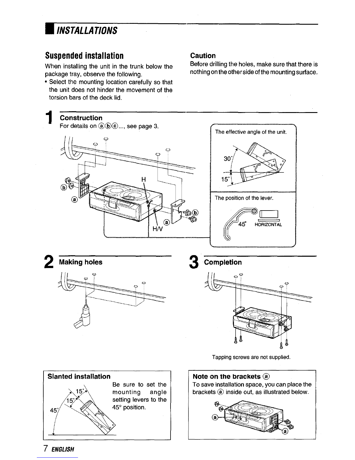
Mounting angle setting levers
Be sure to change the position of both mounting
angle setting levers according to the angle at
which the unit is to be installed.
Mounting angla setting levers
Insert apointed object such as ascrew driver or
ball-point pen, etc. into the low spot of the lever
and slide the lever to the position from among
HORIZONTAL, 45°, and VERTICAL positions.
Notes
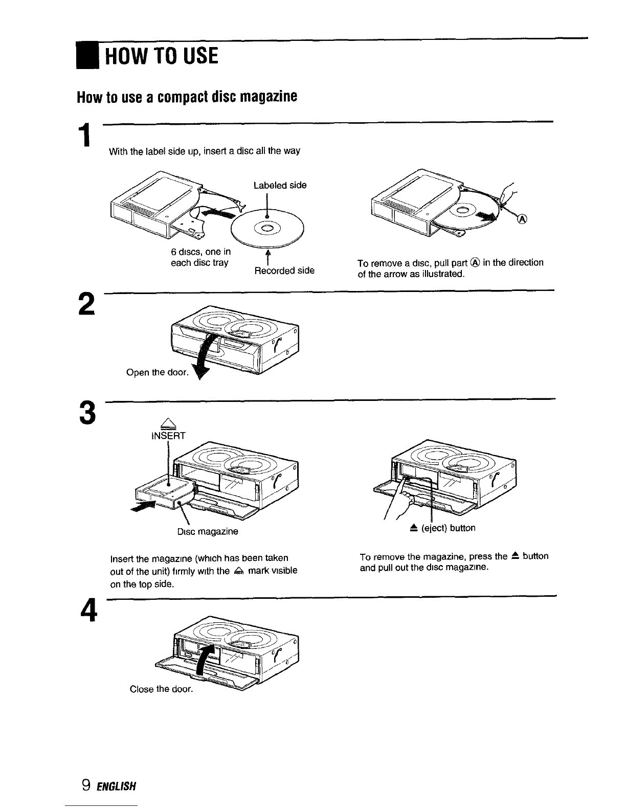
●Be sure to eject the disc magazine when you set the
levers.
●Be sure to set both levers to the same position.
●Be sure to set the levers exactly at the position (notch).
Ifthe lever is deviate from the position, the sound may
drop out.
.Care must be taken when you mount the unit at the
angle of lower than level. The diet magazine may drop
if you eject the magazine.
●Do NOT turn over the unit or slide the lever when the
unit isactivated. Doing so may damage the mechanism
or the discs in the unit.
.The mounting angle setting levers on each side of the
unit are factory-set to the HORIZONTAL position.
●When you complete the setting, attach the supplied
adhesive labels @over the slots.
ENGLISH 4

hINSTALLATIONS
Horizontal installation
Construction
For details on @@@..., see page 3.
Note
If the mounting surface needs to be strengthened,
secure the plate brackets @to the bottom surface of the
car trunk, etc. with the tapping screws (not supplied).
2Deciding the position
3Removing temporarily
The effective angle of the unit.
The position of the lever.
4Making holes in the carpet
5Completion

Vertical installation
1Construction
For details on @@@..., see page 3.
Note
●Ifthe mounting surface needs to restrengthened,
secure the plate brackets@to the bottom surface
of,the car trunk, etc. with the tapping screws (not
supplied).
2
3
Deciding the position
plate
@if it
n9.
—
Removing temporarily
●If installation space is narrow, bend the plate bracket
@back and forth along the perforated line to break off
the end.
4
5
Making holes in the carpet
Completion
ENGLISH 6

~INSTALLATIONS
Suspended installation Caution
When installing the unit in the trunk below the Before drilling the holes, make sure that there is
package tray, observe the following. nothing on the other side of the mounting surface.
●Select the mounting location carefully so that
the unit does not hinder the movement of the
torsion bars of the deck lid.
1Construction
For details on @@@..., see page 3. The effective angle of the unit.
“d: 0\’-=. -
1YF
The position of the lever.
!“@@ ‘n
—\@Jw -’
FIN 4!3 H-L
2Making holes
Slanted installation Be sure to set the
A
15“ mounting angle
15“ setting levers to the
45” 45° position.
. .
3Completion
Tepping screws are not supplied
Note on the brackets@
To save installation space, you can place the
brackets @inside out, as illustrated below.
7ENGLISH

~CONNECTIONS
This unit is designed only for AIWA brand car
stereo. Therefore you can not use the unit with
other brand’s equipment.
+r
to AIWA brand car stereo
Caution Note
Be sure to disconnect the ground wire terminal of Use only the supplied connecting cable. Using an
the car battery before making aconnection in unspecified connecting cable may cause background
noise.
order to prevent short circuiting.
ENGLISH 8

,HOW TO USE
How to use acompact disc magazine
1.
2
3
4
With the label side up, insert adisc all the way
*& a
6discs, one in
each disc tray t
Recorded side To remove adisc, pull part@ in the direction
of the arrow aa illustrated.
Open the
A
INSERT
Dlac magazine A(eject) button
Insert the magazme (which has tIeen taken To remove the magazine, press the ~button
out of the unit) fv’mly wkh the .4A mark visible and Pull out the disc magazme.
on the top side.
Close

~SPECIFICATIONS
Notes on the disc magazine
●Be sure to place adisc on the disc tray with the
label side up. If adisc is not set properly, it may
cause damage to the unit.
Disc magazine
0
●The disc tray may be taken off from the magazine
if you pull the tray forcibly. If the tray is taken
out, put it back into the magazine as illustrated.
Be sure that both ends of the tray are aligned to
the grooves of the magazine correctly.
Compact disc changar
System Compact disc digital audio
system
Frequency response 5Hz – 20 kHz
Wow and flutter Below measurable limit
Si9naI to nOiSe ratio 91 dB or more
outputs Line output (for changer
connector only)
Operating temperature –1o “c to 55 “c
Dimensions 244 x63x 169 mm (w/h/d)
(9 5/8X 21/2 x65/8in,)
Weight 1.8 kg
(3.96 Ibs.)
Power requirement 12 VDC car battery
(negative ground)
WA converter 1bit DAC, 8times over
sampling
Sampling rate 44.1 kHz
Disc size 120 mm
Supplied accessories Disc magazine (1)
Mounting kit (1 set)
Connecting cable (5 m)
(16.4 ft.) (1)
Design and specifications are subject to change without
notice.
●Be sure all the trays are set in the magazine
when using the unit.
ENGL/SH 10

Bienvenidos
Muchas gracias por su compra de este producto AlWA. Para utilizar este aparato en Ias mejores
condlclones posibles, lea cuidadosamente Ias instrucciones de este manual.
~INDICE
EDETALLES
●Sepueden seleccionar yreproducir canciones PRECAUTION
de 6discos compactoscolocados en el cargador Las modificaciones yajustes de este producto
de discos. que no han sldo autorizadas atkulo expreso por
●Se puede instalar horizontalmente, el fabricate pueden anularel derecho oautoridad
verticalmente, inclinado ycolgado de algtin del usuario para hater funcionar este producto.
Iado.
●Atraves de la ventana encima del aparato
podra ver el disco que gira durante su
reproduction.
●Como el tamafio de este aparato es menor, es
mas facil de instalar.
iESPANOL

■PRECAUCIONES
●NO instale la unidad en un Iugar donde pueda
quedar expuesto a:
—Ios rayos del sol o a temperatures muy altas.
—Iiquido, Iluvia ohumedad.
—demasiada suciedad opolvo
—vibration excesiva
●Este aparato funciona solo con CC de 12 voltios
con conexion atierra negativa.
●Seleccione cuidadosamente el Iugar para la
instalacion detal forma que elaparato no interfiera
con Ias funciones de conduction normales.
●Antes de hater Ias conexiones, desconecte el
terminal ~de la bateria del coche para evitar
un cortocircuito.
Notas sobre Ios discos compactos
●Sise ha colocado un disco sucio ocon defectos
en el cargador de discos, el sonido puede
desaparecer aveces durante su reproduction.
●Sujete el disco por sus hordes interiors y
exteriors.
●NO toque el Iado de la superficie sin etiqueta
dei disco.
●NO pegue papeles ni cintas, etc. en el disco.
●NO deje que el disco quede en un Iugarexpuesto
aIos rayos del sol o a temperatures muy altas.
●Limpie Iosdiscos antes decolocarlos enelcargador
de discos. Empiece siempre por el centro yvaya
hacia afuera Iimpiando con un paho Iimpiador,
●Pueden quedar rebabas en Ios hordes interior
yexterior de un disco nuevo. Las rebabas
pueden provocar una averia del aparato o
caidas en el sonido. Para evitar estos
problemas, si quedan rebabas en el disco,
eliminelas con un bolfgrafo, etc., tal como en la
ficrura.
Bol~grafo
Rebabas m
o
R
Y
Rebabas @21
p
Bollgrafo
●NO utilice disolventes tales como bencina o
alcohol para Iimpiar un disco.
●NO se pueden reproducerIosdiscos compactos de
8cm (3 puigadas) ni siquiera colocandolos en un
adaptador disehado especialmente para tal efecto.
●NO utilice discos compactos de formas
irregulars (per ejemcrlo con forma de corazon
uoctogonales). Pueden provocar una averfa.
Notas sobre el cargador de discos
●NO deje el cargador de discos en un Iugar
donde quede expuesto agrandes temperatures
oIugares muy humedos.
●NO coloque mas de un disco en cada ranura.
●NO deje caer el cargador de discos.
ESPAhOL 2

■DESEMBALAJE
Cambiador de discos Cargador de discos Cable de conexion
compactos compactos
@
Qq.j
Juego de montaje suministrado
para el cambiador de discos compactos
Las Ietras en circulos tienen sus referencias a 10Iargo de Ias instrucciones.
Utilice solo Ias piezas para montaje suministradas para que la instalacion sea segura.
@Mensulas (1 par) @Tornillos con
arandela (4 c/u)
@Etiqueta adhesiva (1 hoja)
G
UD
@Mensulas de @Tuercas (4 c/u)
placa (2 c/u)
R
@
e
8B
%.= .
3ESPAfiOL

●INSTALACIONES
Precauciones
Seleccione cuidadosamente el Iugar donde se
vaa instalar, teniendo encuenta lossiguientes
puntos.
●Confirmeque nohayauntanque decombustible
detrasde Iasupetficie de montaje yquetampoco
haya cables ocaries.
●Lainstalacion delaunidad nodeberaimpedirel
movimiento de la tapa del haul ni el desmontaje
de la rueda de repuesto, etc.
●Utilice solo el juego de montaje suministrado
con el equipo para que la instalacion se haga
correctamente yde forma segura.
Desmontaje de Ios tornillos de
transporIe
Busque Ios tres tornillos de transport que estan
en la parte inferior del aparatoy que fijan el
mecanismo del aparato durante su transport.
Saque estos tornillos antes de la instaiacion y
coloque Ias etiquetas adhesivas suministradas
sobre Ios orificios.
Guarde Ios tornillos yvuelva acolocarlos en sus
posiciones originales en caso de Ilevar oenviar
el aparato para su servicio omantenimiento.
Instalacion de Ios herrajes de angulo
Cambie la position de instalacion de Ios herrajes
de anguio de acuerdo al angulo en el que desea
instalar el aparato.
Angulo de instalacion
Introduzca un objeto punfiagudo, por ejemplo un
destornillador superfino obolfgrafo, etc. en Ios
oietes motectores moviles vdeslice Ios oietes
p~otectores ala position des~ada, HORIZON~AL,
45°0 VERTICAL,
Notas
.Expulse sin falta Ios cargadores de disco antes de
colocar 10sojetes protectors.
.Instate ambos ojetes protectors en la misma position.
●Los ojetes protectors deben estar asentados en el
Iugar especificado para la position deseada; de 10
contrario la posici6n de la unidad puede provocar una
caida del sonido,
●Debe tenerse cuidado para instalar el angulo de la
unidad con el Iado delantero mas abajo que el trasero.
El cargadorde disco puede caerse cuando 10expulse.
●NO invierfa la unidad odeslice Ios ojetes protectors
cuando el aparato esta activado. Esto puede dafiar et
mecanismo oIos discos en el aparato.
●Los herrajes de angulo de instalacion en cada Iado de
la unidad se han ajustado de fabrica ala position
HORIZONTAL.
●Cuando se completa el ajuste, pegue Ias etiquetas
adhesivaa @sobre Iks ranuraa.
ESPA~OL 4

nINSTALA(.YONES
Instalacion horizontal
1Disetio
Para mas detalles de @@@..., lea la pagina 3.
Nota
Si fuera necesario reforzar la auperticie de instalacion,
aaegure Ias mensulas de placa @en la superficie
inferior del bad del coche con tornillos autoterrajantes
(no inciuido).
2
3
Decida la position
Desmontaje provisorio
Angulo efectivo del aparato.
Position del ojete protector.
r‘m
4!$ H-L
Abra orificios en la alfombra
Fin
~ESPA)iOL

Instalacion vertical
1Diseho
Para mas detalles de @@@..., lea la pagina 3.
aparato. \ojete protector.
Nota
●Sifuera necesario reforzar la superficie de instalacion, cEl espacio para su instalacion es angosto, doble la
asegure Ias mensulas de placa @en la Supetilcie mensula @hacia atras yhacia adelante a 10Iargo de
inferior del haul del coche con tornillos autoterrajantes la I[nea peforada para romper la punta.
(no incluido),
2Decida la position
nsula
si
rgo.
3Desmontaje provisorio
4Abra orificios en la alfombra
/
v
5Fin
ESPANOL 6

~INSTALACIONES
Instalacion colgada Precaution
Cuando se instala la umdad en el batil, debajo de Verifique que no haya nada detras del Iugar de la
la bandeja para paquetes, tenga en cuenta 10s instalacion antes de abnr Ios orificios.
siguientes puntos.
●Selecclone cuidadosamenteel Iugardondese
vaainstalar launidad, paraqueno impidael
movimlento de Ias barras de soporte de la tapa
del batil.
1Dkeiio
Para mas detalles de @@)@..., lea la pagina 3.
Ill v
Angulo efectwo del aparato.
30”
15“
Posic\on del ojete protector.
2Abra orificios
3’*
Nose mcluve
instalaci6n inctinada Instale Ios herrajes
A
15“ de angulo para la
15“ instalacion ala
45” \
position de 45°.
. .
Nota eobre Ias mensulas @
Paraahorrarespacio al instalar, puede colocar
Ias mensulas @de adentro hacla afuera
como en la figura acontinuation.
7ESPANOL

●CONEXIONES
Este aparato fue diseriado solo para Ios estereos
de coche AlWA. Por 10 tanto, no utilice este
aparato con equipos de otra marca.
+Jr
al estereo de coche de la marca Acompactoa
Precaution Nota
Desconecte el terminal del cable atierra de la Utilicesoloelcabledeconexionsuministrado. Elusode
bater(a del coche antes de hater Ias conexiones, un cable de conexion no especificado puede provocar
ruidos de fondo.
para evitar un cortocircuito.
ESPAifOL 8

●UTILIZATION
Utilization del cargador de discos compactos
1
2
3
4
Coloque el disco compacto hasta el fondo
conel Iadodela etiqueta haciaarriba.
e& e
6discos, uno en
cada bandeja de t
Lado grabado Para sacar un disco compacto, tire de la parte @en
discos el sentido de la flecha, tal como se puede apreciar en
la figura.
Abra la pu
A
lN~RT
Cargador de discos Boton de expulsion A
Coloque el cargador, (despues de sacarlo) Presione el boton Aytire del cargador de
conelladodela marca &haciaarriba. discos.
Cie
9ESPAfiOL
Other manuals for ADC-M60
1
This manual suits for next models
1
Table of contents
Languages:
Other Aiwa CD Player manuals
Popular CD Player manuals by other brands

Sony
Sony SCD-XA777ES - Es Super Audio Cd Player Dimensional information

Sony
Sony CDX-F5505X - Fm/am Compact Disc Player Installation

Panasonic
Panasonic SL-S261C operating instructions

Philips
Philips AZ 1203 Instructions for use

Sony
Sony DNS313F - S2 Sports CD Walkman operating instructions

Sony
Sony CFS-W435S Service manual