5
REF. NO PART NO. KANRI DESCRIPTION
NO.
REF. NO PART NO. KANRI DESCRIPTION
NO.
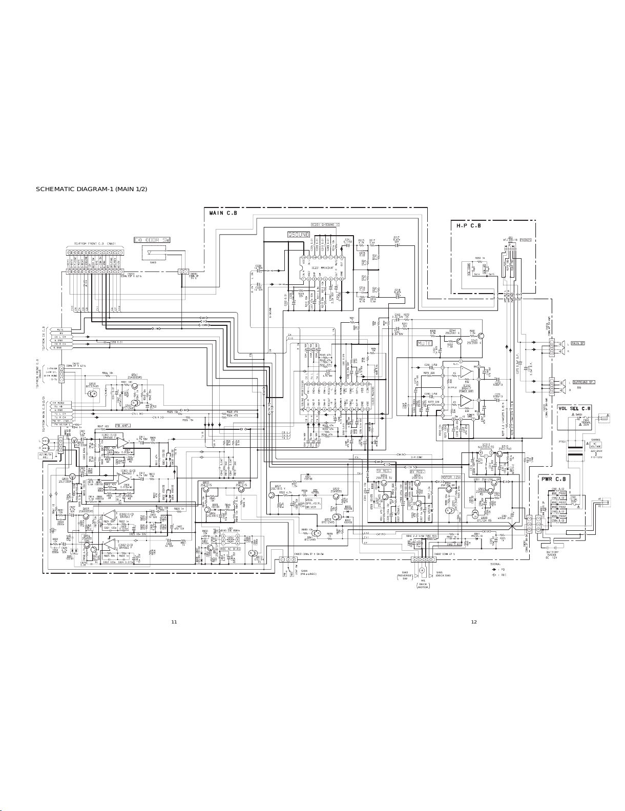
C314 87-010-248-080 CAP, ELECT 220-10V
C315 87-010-197-080 CAP, CHIP 0.01 DM
C321 87-010-190-080 S CHIP F 0.01
C322 87-010-263-080 CAP, ELECT 100-10V
C325 87-010-405-080 CAP, ELECT 10-50V
C801 87-010-402-080 CAP, ELECT 2.2-50V
C802 87-010-402-080 CAP, ELECT 2.2-50V
C803 87-010-177-080 C-CAP,S 820P-50 SL
C804 87-010-177-080 C-CAP,S 820P-50 SL
C805 87-012-158-080 C-CAP,S 390P-50 CH
C806 87-012-158-080 C-CAP,S 390P-50 CH
C809 87-010-406-010 CAP,E 22-50 SM
C810 87-010-406-010 CAP,E 22-50 SM
C811 87-010-404-010 CONDENSER 4.7-50
C812 87-010-404-010 CONDENSER 4.7-50
C815 87-010-374-010 CAP, ELECT 47-10V
C819 87-010-401-010 CAP, ELECT 1-50V
C820 87-010-401-010 CAP, ELECT 1-50V
C821 87-012-153-080 C-CAP,S 120P-50 CH
C822 87-012-153-080 C-CAP,S 120P-50 CH
C823 87-010-213-080 C-CAP,S 0.015-50 B
C824 87-010-213-080 C-CAP,S 0.015-50 B
C825 87-010-405-080 CAP, ELECT 10-50V
C826 87-010-405-080 CAP, ELECT 10-50V
C827 87-010-404-010 CONDENSER 4.7-50
C828 87-010-404-010 CONDENSER 4.7-50
C831 87-010-198-080 CAP, CHIP 0.022
C832 87-010-198-080 CAP, CHIP 0.022
C833 87-010-179-080 CAP,CHIP S B1200P
C834 87-010-248-080 CAP, ELECT 220-10V
C835 87-010-374-010 CAP, ELECT 47-10V
C838 87-010-405-080 CAP, ELECT 10-50V
C839 87-010-186-080 CAP,CHIP 4700P
C840 87-010-186-080 CAP,CHIP 4700P
C841 87-010-194-080 CAP, CHIP 0.047
C842 87-010-194-080 CAP, CHIP 0.047
C843 87-010-190-080 S CHIP F 0.01
C844 87-010-178-080 CHIP CAP 1000P
C846 87-010-194-080 CAP, CHIP 0.047
C849 87-010-184-080 CHIP CAPACITOR 3300P(K)
C850 87-010-184-080 CHIP CAPACITOR 3300P(K)
C851 87-010-186-080 CAP,CHIP 4700P
CF1 87-A90-128-010 FLTR,AM IF CFAL-455
CF2 82-785-747-080 CF,MS2 GHY,R
CF3 82-785-747-080 CF,MS2 GHY,R
CN201 87-099-017-010 CONN, 15P 6216 V
CN203 87-049-469-010 CONN,4P V
CN204 87-049-469-010 CONN,4P V
CN205 87-A60-109-010 CONN,2P V S2M-2W
CN301 87-049-919-010 CONN,3P EH V WHT
CN801 87-049-469-010 CONN,4P V
CN802 87-099-186-010 CONN,6P EH V WHT
CN802 87-099-186-010 CONN,6P EH V WHT
CN802 87-099-186-010 CONN,6P EH V WHT
CN803 87-049-919-010 CONN ASSY, 3P PWR
D3 87-A40-226-080 VARI-CAP,SVC251SPA
L2 87-A50-347-010 COIL,FM BPF EX
L3 87-A50-350-010 COIL,BAR ANT AMN (COI)<HRSC>
L3 87-A50-349-010 COIL,BAR ANT AMW (COI)<HASC>
L4 87-A50-345-010 COIL,FM RF EX
L5 87-A50-343-010 COIL,FM OSC EX
L6 87-A50-337-010 COIL,AM OSC (TOKO)
L7 87-A50-336-010 COIL,AM IFT (TOKO)
L8 87-A50-335-010 COIL,FM IFT (TOKO)
L9 87-A50-334-010 COIL,FM DET (TOKO)
L10 87-003-102-080 COIL, 10UH
L801 87-007-342-010 COIL,OSC 85K BIAS
R840 87-029-124-010 RES,FUSE 2.2-1/4
SW1 8Z-CD9-640-010 SW,SL 2-4-2 SK42H01G4
PVC1 87-A91-168-010 TUN-CAP,20P-140P FA-22124 N000
<HRSC>
PVC1 87-A91-167-010 TUN-CAP,20P-160P FA-22125 N000
<HASC>
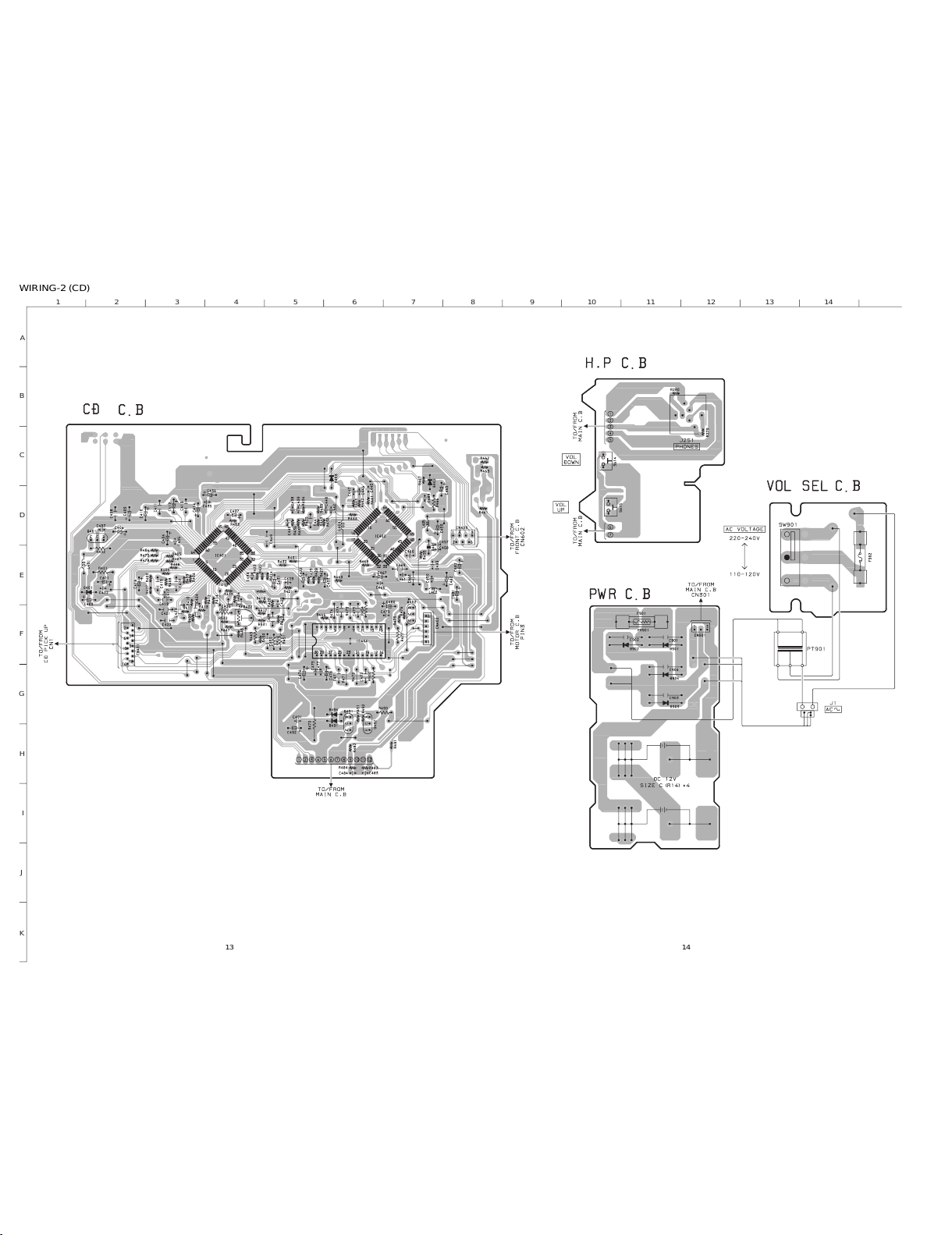
CD C.B
C401 87-010-403-080 CAP, ELECT 3.3-50V
C402 87-010-197-080 CAP, CHIP 0.01 DM
C403 87-010-263-080 CAP, ELECT 100-10V
C404 87-010-248-080 CAP, ELECT 220-10V
C405 87-010-197-080 CAP, CHIP 0.01 DM
C406 87-010-374-080 CAP, ELECT 47-10V
C407 87-010-178-080 CHIP CAP 1000P
C409 87-010-248-080 CAP, ELECT 220-10V
C410 87-010-263-080 CAP, ELECT 100-10V
C412 87-010-401-080 CAP, ELECT 1-50V
C413 87-010-197-080 CAP, CHIP 0.01 DM
C414 87-010-405-080 CAP, ELECT 10-50V
C416 87-010-545-080 CAP, ELECT 0.22-50V
C417 87-012-157-080 C-CAP,S 330P-50 CH
C425 87-010-176-080 C-CAP,S 680P-50 SL
C429 87-010-186-080 CAP,CHIP 4700P
C430 87-012-156-080 C-CAP,S 220P-50 CH
C431 87-010-545-080 CAP, ELECT 0.22-50V
C432 87-010-374-080 CAP, ELECT 47-10V
C433 87-010-401-080 CAP, ELECT 1-50V
C435 87-010-197-080 CAP, CHIP 0.01 DM
C436 87-010-374-080 CAP, ELECT 47-10V
C437 87-010-404-080 CAP, ELECT 4.7-50V
C438 87-010-196-080 CHIP CAPACITOR,0.1-25
C439 87-010-178-080 CHIP CAP 1000P
C440 87-010-147-080 C-CAP,S 3P-50 CH
C442 87-010-313-080 CAP, CHIP 18P
C445 87-010-196-080 CHIP CAPACITOR,0.1-25
C446 87-010-196-080 CHIP CAPACITOR,0.1-25
C447 87-010-196-080 CHIP CAPACITOR,0.1-25
C448 87-010-315-080 C-CAP,S 27P-50 CH
C450 87-012-140-080 CAP 470P
C457 87-010-312-080 C-CAP,S 15P-50 CH
C458 87-010-312-080 C-CAP,S 15P-50 CH
C459 87-010-263-080 CAP, ELECT 100-10V
C460 87-010-196-080 CHIP CAPACITOR,0.1-25
C461 87-010-196-080 CHIP CAPACITOR,0.1-25
C462 87-010-370-080 CAP,E 330-6.3 SME
C463 87-010-197-080 CAP, CHIP 0.01 DM
C463 87-010-184-080 CHIP CAPACITOR 3300P(K)
C465 87-010-404-080 CAP, ELECT 4.7-50V
C466 87-010-196-080 CHIP CAPACITOR,0.1-25
C467 87-010-263-080 CAP, ELECT 100-10V
C468 87-010-196-080 CHIP CAPACITOR,0.1-25
C469 87-012-154-080 C-CAP,S 150P-50 CH
C471 87-010-196-080 CHIP CAPACITOR,0.1-25
C472 87-010-196-080 CHIP CAPACITOR,0.1-25
C473 87-010-196-080 CHIP CAPACITOR,0.1-25
C474 87-010-196-080 CHIP CAPACITOR,0.1-25
C475 87-010-197-080 CAP, CHIP 0.01 DM
C476 87-010-236-080 CAP,E 1000-10 SME
C477 87-010-197-080 CAP, CHIP 0.01 DM
C478 87-010-263-080 CAP, ELECT 100-10V
C479 87-010-197-080 CAP, CHIP 0.01 DM
C480 87-010-221-080 CAP, ELECT 470-10V
C481 87-010-405-080 CAP, ELECT 10-50V
C482 87-010-405-080 CAP, ELECT 10-50V
C483 87-012-156-080 C-CAP,S 220P-50 CH
C484 87-012-156-080 C-CAP,S 220P-50 CH
C489 87-010-196-080 CHIP CAPACITOR,0.1-25
C490 87-010-196-080 CHIP CAPACITOR,0.1-25
C491 87-010-197-080 CAP, CHIP 0.01 DM
C492 87-010-221-080 CAP, ELECT 470-10V
C493 87-010-322-080 C-CAP,S 100P-50 CH
CN401 87-A60-424-010 CONN,16P V TOC-B