Aiwa TV-FA2110 User manual

SERVICE MANUAL
DATA
TV-FA2110
SHJ2
KERJ2
KER71
COLOR TELEVISION
S/M Code No. 09-023-457-3R1
REVISION
This Service Manual is the “Revision Publishing” and replaces “Simple Manual”
(S/M Code 09-023-457-3T1).
d u
p a
t o
r

-2-
TABLE OF CONTENTS
NOTICES BEFORE REPAIRING ........................................................................................................................ 3
SPECIFICATIONS ............................................................................................................................................... 4
ACCESSORIES PARTS LIST -1/1 ...................................................................................................................... 5
DISASSEMBLY ...............................................................................................................................................6-10
ELECTRICAL PARTS LIST ..........................................................................................................................11-20
WIRING-1/3 (MAIN) ........................................................................................................................................... 21
SCHEMATIC DIAGRAM-1/3 (MAIN) .................................................................................................................. 22
WIRING-2/3 (NK) ............................................................................................................................................... 23
SCHEMATIC DIAGRAM-2/3 (NK)...................................................................................................................... 24
WIRING-3/3 (AUDIO) ........................................................................................................................................ 25
SCHEMATIC DIAGRAM-3/3 (AUDIO) ............................................................................................................... 26
TRANSISTOR ILLUSTRATION-1/1 ................................................................................................................... 27
WAVEFORMS ..............................................................................................................................................28-29
IC BLOCK DIAGRAM....................................................................................................................................30-31
SET-UP FOR ADJUSTMENT .......................................................................................................................32-35
ELECTRICAL ADJUSTMENT .......................................................................................................................36-48
MECHANICAL EXPLODED VIEW-1/1 .............................................................................................................. 49
MECHANICAL PARTS LIST -1/1 ....................................................................................................................... 50
COLOR NAME TABLE-1/1 ................................................................................................................................ 51
OTHER PARTS LIST -1/1.................................................................................................................................. 52
d u
p a
t o
r

-3-
NOTICES BEFORE REPAIRING
To make the best use of this equipment, make sure to
obey the following items when repairing (or mending).
1. Do not damage or melt the tunicate of the leading
wire on the AC1 side, including the power supply
cord.
2. Do not soil or stain the letters on the spec.
inscription plates, notice labels, fuse labels, etc.
3. When repairing the part extracted from the
conducted side of the board pattern, fix it firmly
with applying bond to the pattern and the part.
4. Restore the following items after repairing.
1) Conditions of soldering of the wires (especially,
the distance on the AC1 side).
2) Conditions of wiring, bundling of wires, etc.
3) Types of the wries.
4) Attachment conditions of all types of the insulation.
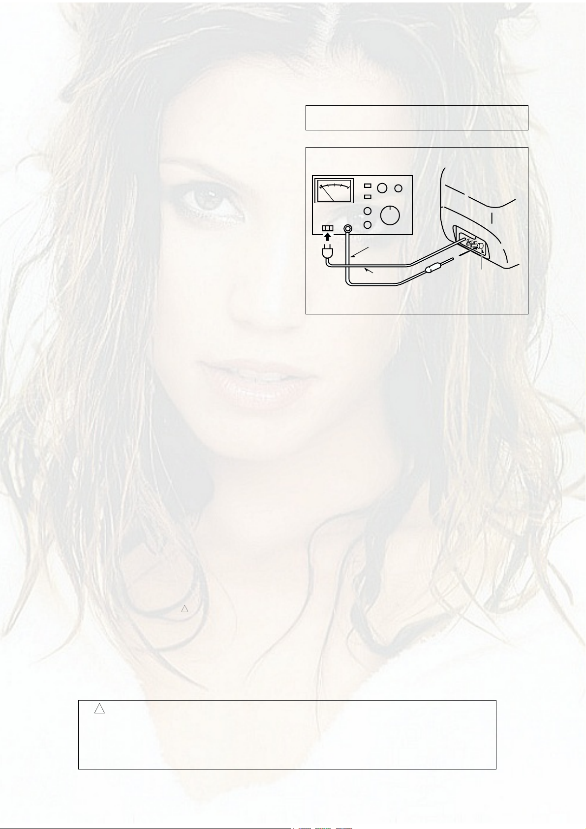
5. After repairing, always measure the insulation
resistance and perform the voltage-withstand test
(See Fig-1).
1) The insulation resistance must be 7.0 to 9.5 M
when applying 500V per second.
2) In the voltage withstand test, apply 3 kV for 1
minute and check that the GO lamp lights.
* Breaking current set to 10 mA.
* Connect the safety checker as shown in Fig-1,
then measure the resistance and perform the test.
* Do not touch the equipment during testing.
* For details of the safety checker, refer to the supplied
Operation manual.
Fig-1
Safety checker (Model 7110, etc.)
Earth cable
AC cable Connectthe earth cable
totheoutside metal part
terminal.
Insulation resistance: 7.0 to 9.5 M (500 V/s)
Voltage-withstand: 3 kV for 1 minute
Safety Components Symbol
This symbol is given to important parts which serve to maintain the safety of the product, and which
are made to confirm to special Safety Specifications.
Therefore, when replacing a component with this symbol make absolutely sure that you use a
designated part.
!
When servicing and checking on the TV, note the followings.
board. The inside wiring is designed not to get close to
the pyrogenic parts and high voltage parts. Therefore,
put these parts in the original positions.
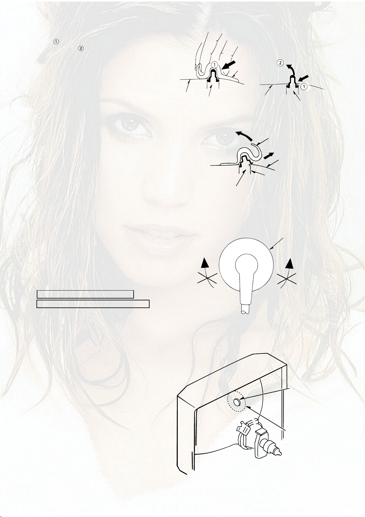
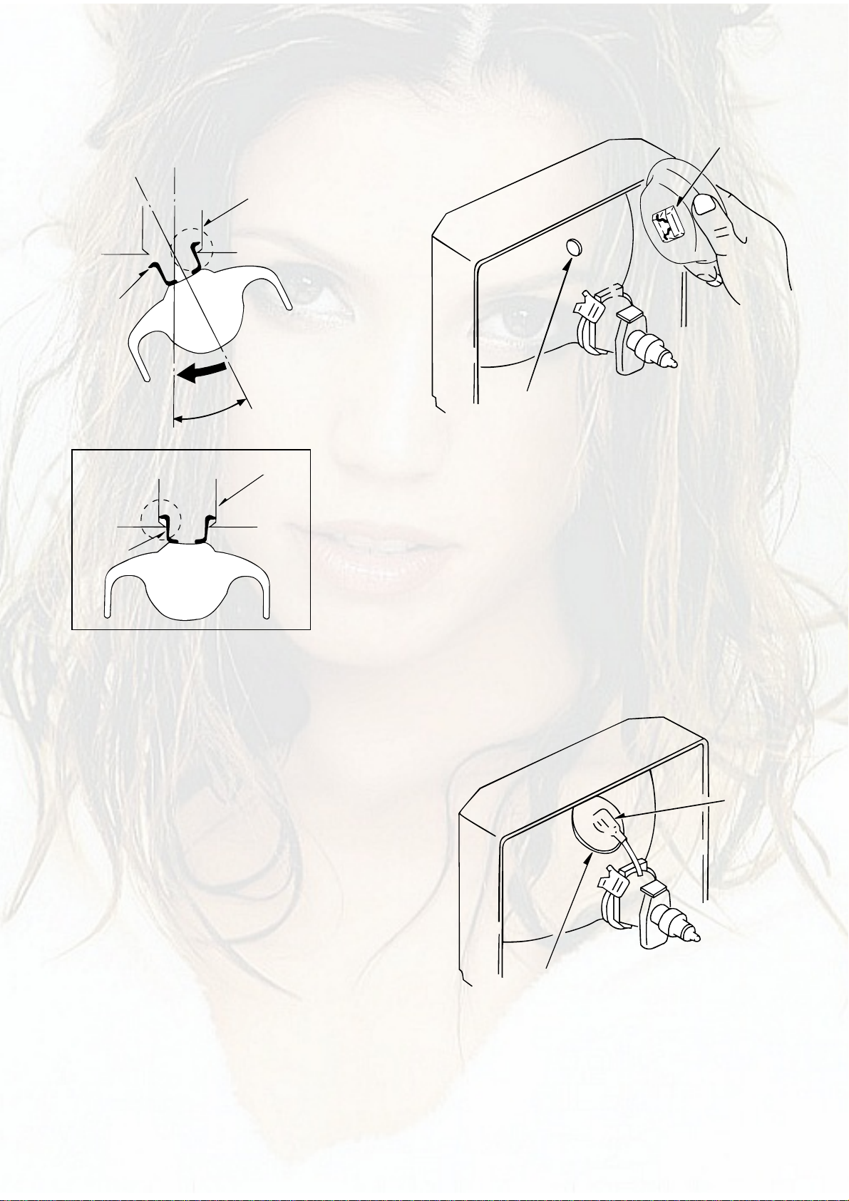
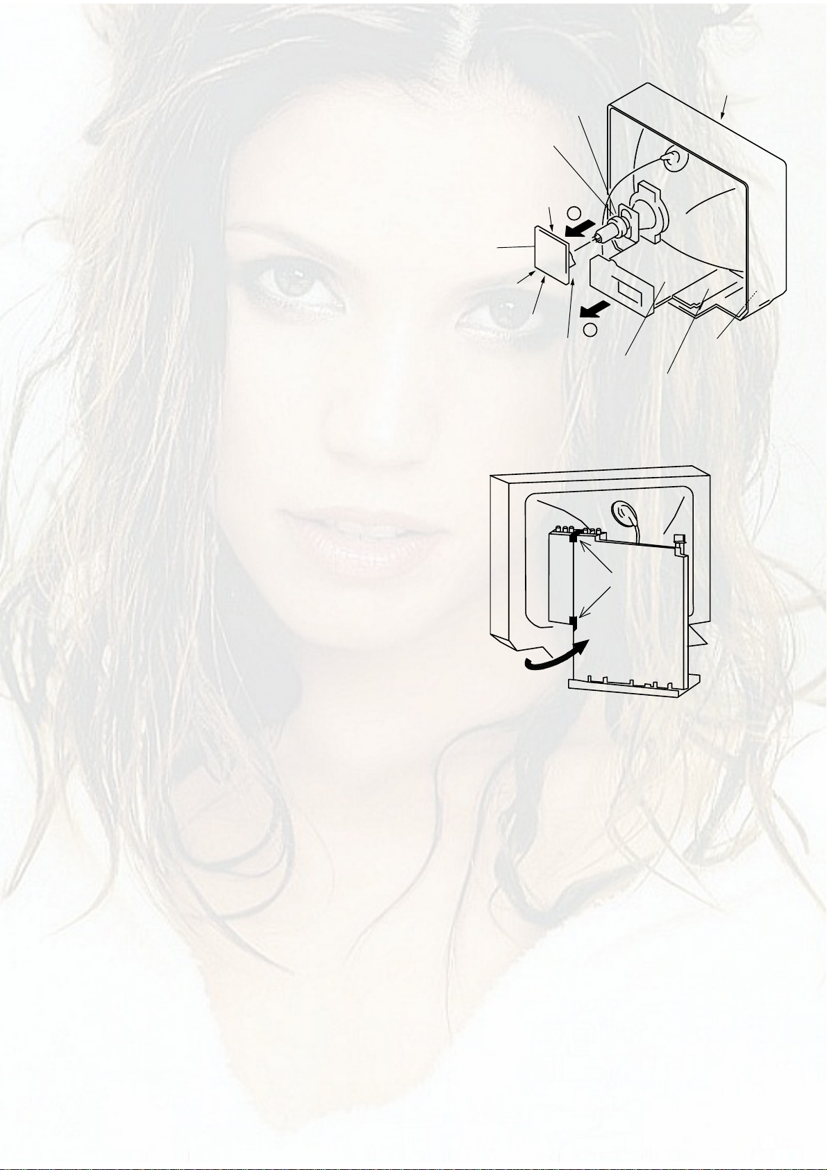
5. Take care of the cathode-ray tube.
By setting an explosion-proof cathode-ray tube in this
equipment, safety is secured against implosion.
However, when removing it or servicing from the
back, it gives out shock that is dangerous. Take
enough care to deal with it.
6. Avoid an X-ray.
Safety is secured against an X-ray by giving
considerations to the cathode-ray tube and the high
voltage peripheral circuit, etc. Therefore, when
repairing the high voltage peripheral circuit, use the
designated parts and do not change the circuit.
Repairing, except indicates, causes rising of high
voltage, and the cathode-ray tube emits an X-ray.
7. Perform a safety check after servicing.
Confirm that the screws, parts and wiring which were
removed in order to service are put in the original
positions, or whether there are deteriorated portions
around the places serviced.
1. Keep the notices.
As for the places which need special attentions, they
are indicated with labels or seals on the cabinet,
chassis and parts. Make sure to keep the indications
and notices in the operation manual.
2. Avoid an electric shock.
There is a high voltage part inside. Avoid an electric
shock while the electric current is flowing.
3. Use the designated parts.
The parts in this equipment have the specific
characteristics of incombustibility and withstand voltage
for safety.
Therefore, use a part which has the same character
as the replaced part. Especially as to the important
parts for safety which is indicated in the circuit
diagram or the table of parts with a mark, the
designated parts must be used.
4. Put parts and wires in the original position after
assembling or wiring.
There are parts which use the insulation material such
as a tube or tape for safety, or which are assembled so
that these parts do not make contact with the printed
!
d u
p a
t o
r

-4-
SPECIFICATIONS
KERJ2, KER71M MODEL
SHJ2 MODEL
Tuner system .............................. Frequency synthesized tuner
Screen Size................................. 406 (W) ×305 (H) mm (16 ×12
1
/
8
in.)
508 mm (Visual diagonal) (20 in.)
TV system ................................... PAL-B/G, D/K, H, I
SECAM-B/G, D/K, K1, I
NTSC-M
NTSC3.58 (5.5, 6.0, 6.5 MHz)
NTSC4.43 (5.5, 6.0, 6.5 MHz)
PAL60 (5.5, 6.0, 6.5 MHz)
SECAM60 (5.5, 6.0, 6.5 MHz)
Color system ............................... PAL, SECAM, PAL60, SECAM60, NTSC3.58, NTSC4.43
Channel coverage ....................... VHF: E2-E12
UHF: E21-E69
CABLE: S1-S41
Antenna input .............................. 75 ohms, unbalanced
Video input .................................. 1 Vp-p, 75 ohms
Video output ................................ 1 Vp-p, 75 ohms
Audio input .................................. 0.5 Vrms, 33 K ohms more
Audio output ................................ 0.5 Vrms, 2.2 K ohms less
Speaker....................................... 120 mm ×60 mm, 8 ohms
Speaker output............................ 7 W + 7 W (THD 10 %)
Operating temperature ................ 5˚C to 40˚C
Operating humidity ...................... 35 % - 80 %
Power requirements .................... 110-240 V AC, 50/60 Hz
Power consumption .................... 98 watts (Standby mode: 8 watts)
Dimensions ................................. 610 (W) ×440 (H) ×485 (D) mm
Weight ......................................... Approx. 26.5 kg
Designand specificationsare subjecttochange withoutnotice forthe purposeof performanceimprovement.
d u
p a
t o
r

! = ! SAFTY PARTS
C = Components marked
All components used on this model at the production line are shown in this service manual.
However, please note that not all components will be available as spare parts for after-sales service.
Components marked S and O are designated as spare parts for service and will be stocked at the spare parts centers.
Components marked X and R are not designated as spare parts for after sales service, and will not be stocked at the spare parts centers.
UNIT-NAME ! C REF-NO PARTS-NO PARTS-NAME SUFFIX&MODEL
-5-
ACCESSORIES PARTS LIST -1/1
TV-FA2110 TV-FA2110 TV-FA2110
KER71M KERJ2C SHJ2C
O AS1001 8B-JEU-906-010 IB,KE (E/CH/A/PE) TV-FA2110 -M a . .
O AS1001 8B-JEU-901-010 IB,KE (E/CH/A/PE) TV-FA2110 -S . b .
O AS1001 8B-JEU-903-010 IB,SH (E/CH/A/PE) TV-FA2110 -S . . c
O AS1002 8B-JBC-950-010 RC UNIT,RC-BVT08 a b c
d u
p a
t o
r
Table of contents
Other Aiwa TV manuals

Aiwa
Aiwa TV-F2400u User manual

Aiwa
Aiwa TV-C2121/KE/KER User manual

Aiwa
Aiwa TV-20ST5 User manual

Aiwa
Aiwa TV-A2018 User manual

Aiwa
Aiwa TV-AR295RHB User manual

Aiwa
Aiwa TV-CN143HS User manual

Aiwa
Aiwa TV-14MT11 User manual

Aiwa
Aiwa TV-AS215 User manual

Aiwa
Aiwa TV-C142S KEJ4C User manual

Aiwa
Aiwa TV-AS215 User manual