_
TABLE
OF
CONTENTS
INTRODUCTION
FEATURES
vricc.iteae
ave
cysciettct
tet
tes
ae
ick
setel
tee
taocy
below
PRECAUTIONS
25.
scasinoscdecsasetecdeccvslectdvdstunsnsashetateiuseaceictt
4
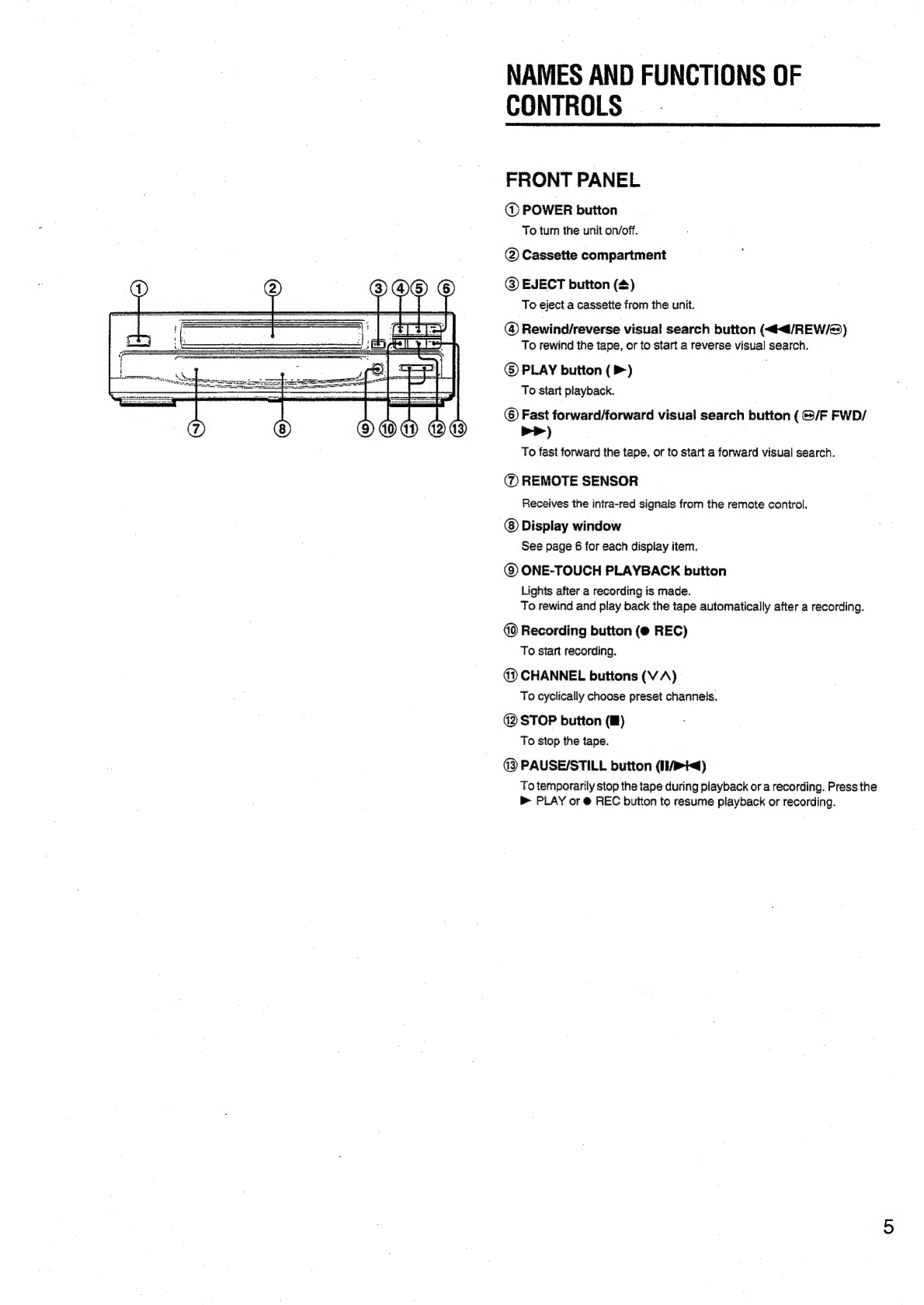
NAMES
AND
FUNCTIONS
OF
CONTROLS.
.......cccesceseseees
5
PREPARATION
;
CONNECTING
AERIAL~SATELLITE-VIDEO-TV
..........0-.
8
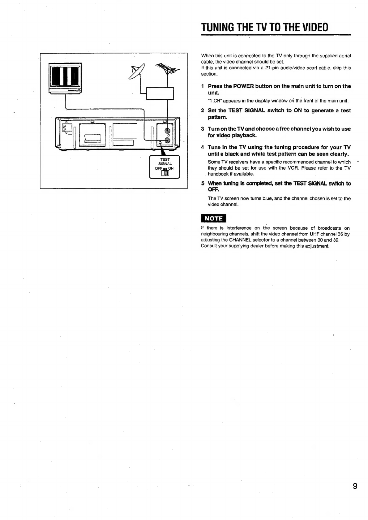
TUNING
THE
TV
TO
THE
VIDEO
oe
lcecsessseeeceeceeseee
9
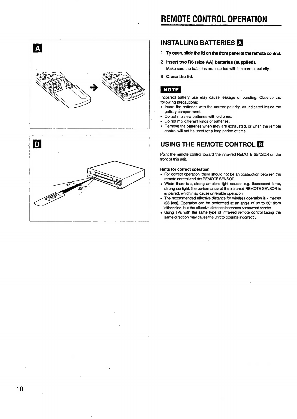
REMOTE
CONTROL
OPERATION
.......cceescscssssssceeeescers
10
SETTING
UP
THE
VIDEO
........ccccccccesssssesscectecscesessencaes
11
ON-SCREEN
FUNCTION
DISPLAY...
eceeeeececeeeseeee
12
ON-SCREEN
DISPLAY
(OSD)
MENU
ooo
cecceseeseees
13
SETTING
THE
CLOCK
.........ccccccscssecscssvececssscsscectecsecareaceee
14
USING
THE
SYSTEM
MENU
uc
cccceeecceesseeseseeeesees
15
TUNING
IN
THE
VIDEO
02...
ecceccccsccsesesssseccsececeecsecscenees
16
PLAYBACK
PLAYING
BACK
A
TAPE
........ccccscsscsscssssssseatocesesssesceceacars
17
FINDING
DESIRED
LOCATIONS
ON
TAPE...
19
GETTING
A
BETTER
PICTURE.........c.cccecccsscseesessereeecere
21
MEMORY
FUNCTIONS
..........ccccsecsessesscsscscsecerssesseessrcsseees
22
RECORDING
BASIC
RECORDING
.......csccecsescesssesssecsesssesstssseesersecacerers
23
TIMER
RECORDING
USING
VIDEO
Plus+
SYSTEM
.....24
TIMER
RECORDING
WITHOUT
VIDEO
Plus+
SYSTEM
csisehsces
esis
ctastasdanelicerwscticueaeea
keen
tan
26
QUICK
TIMER
RECORDING
.........cssessessssrssesssesscececevenes
28
RECORDING
FROM
OTHER
EQUIPMENT
........c.eeseee
29
REFERENCE
TROUBLESHOOTING
GUIDE
ou...
cece
cseseseceseessecseeeses
30
SPECIFICATIONS
..........0046
fubsasesdeacdes
cond
stvoduandeiesissedsdecaoiety
31
1
AUTO
SET
System
2
PDC
(Programme
Delivery
Control)
System
3
VIDEO
Plus+
System
4
“One-Touch
Playback”
Capability
5
Auto
Head
Cleaning
System
6
Quick
Start
Mechanism
7
Digital
Auto
Tracking
8
VHS
Index
Search
System
9
Linear
Time
Counter
10
Fuil-Auto
Functions
11
DA
(Double
Azimuth)
4-head
Configuration