AJAX vhfBridge User manual

vhfBridge User manual
Updated August 8, 2023
vhfBridge is a module for connecting Ajax security systems to third-party VHF
transmitters. It provides 8 transistor outputs for connection to third-party VHF
transmitters.
The device is powered from 100–240 V~ mains and can be operated from a 12
V
⎓
backup battery.
vhfBridge operates as part of the Ajax security system and connects to the hub
via the secure radio communication protocol. The hub communication
range is up to 1,800 meters without obstacles. Supplied in two congurations:
with a casing and without it.
Functional elements
Casing elements
Jeweller
Buy vhfBridge
We value your privacy
We use cookies to enhance your browsing experience, serve personalized ads or content, and analyze our trac. By
clicking "Accept All", you consent to our use of cookies.Cookie Policy
Reject All Accept AllCustomize

vhfBridge board elements
1. Screws securing the casing lid. Unscrew with a bundled hexagon key (Ø
4mm).
2. Space for a 12 V
⎓
backup battery.
Battery not included with vhfBridge set.
3. QR code with the device ID. It is used to pair the device with the Ajax
security system.
4. Perforated part of the casing. Necessary for tamper triggering in case of any
attempt to detach the device from the surface.
5. Perforated parts of the casing for cable output.
The presence of the casing depends on the vhfBridge package. The device is
supplied in two congurations: with a casing and without it.
We value your privacy
We use cookies to enhance your browsing experience, serve personalized ads or content, and analyze our trac. By
clicking "Accept All", you consent to our use of cookies.Cookie Policy

vhfBridge terminals
1. Terminals for connecting a 12 V
⎓
backup battery.
2. 100–240 V~ power supply input.
3. Tamper button. Signals if vhfBridge casing lid is removed.
4. Power button.
5. LED indicator.
6. QR code with the device ID. It is used to pair the device with the Ajax
security system.
7. Terminals for connecting a VHF transmitter.
BATT — input for the 12 V
⎓
backup power connection.
We value your privacy
We use cookies to enhance your browsing experience, serve personalized ads or content, and analyze our trac. By
clicking "Accept All", you consent to our use of cookies.Cookie Policy

LED indication
vhfBridge LED indicator may light up white, red, or green, depending on the
status of the device.
Please note that the LED indicator is not visible when the casing lid is closed.
The LED indicator is used at the stage of vhfBridge connecting and conguring.
Later on, the state of the device can be monitored in the Ajax app.
LED indication Event Note
Lights up white.
Connection with the hub is
established, external power
supply is connected.
Lights up red.
There is no connection with
the hub, external power supply
is connected.
For example, the hub is turned
off or vhfBridgeis outside the
coverage area of the hub’s
wireless network.
Goes out for 0.5 seconds, then
lights up green and turns off. Enabling vhfBridge.
Goes out for 0.5 seconds, then
lights up green and fades out
over 3 seconds.
Disabling vhfBridge.
OUT — power output for the 12 V
⎓
VHF transmitter (maximum output
current is 2 A).
OUT 1…8— vhfBridge outputs for connecting a VHF transmitter.
We value your privacy
We use cookies to enhance your browsing experience, serve personalized ads or content, and analyze our trac. By
clicking "Accept All", you consent to our use of cookies.Cookie Policy

Blinks red once per second. vhfBridge is not assigned to a
hub.
Lights up for a second once
every 10seconds.
No external power supply is
connected to vhfBridge.
The colour of the indication
depends on the status of
connection with the hub:
During an alarm, gradually
lights up and goes out once
every 10seconds.
No external power supply and
discharged external battery of
vhfBridge.
The colour of the indication
depends on the status of
connection with the hub:
LED indication of output status
LED indication Output status in case of alarm
High potential output (positive trip). Lights up green.
Low potential output (negative trip). Goes out.
Operating principle
vhfBridge is designed to connect third-party VHF transmitters to create an
additional channel for transmitting events to the CMS.
The communication channel with the CMS created using vhfBridge can be used
as the only or as a backup channel for communicating with the CMS
(recommended more reliable option). This means that the hub can
simultaneously transmit all events and alarms to the monitoring station of the
lights up white if there is
connection with the hub;
lights up red if there is no
connection with the hub.
lights up white if there is
connection with the hub;
lights up red if there is no
connection with the hub.
We value your privacy
We use cookies to enhance your browsing experience, serve personalized ads or content, and analyze our trac. By
clicking "Accept All", you consent to our use of cookies.Cookie Policy

security company not only through SIA (DC-09), ADEMCO 685, SurGard (Contact
ID), and other proprietary protocols but also using vhfBridge.
The transponder receives information about alarms and events from the hub via
the Jeweller radio channel. Then, vhfBridge transmits it to a third-party VHF
transmitter via wires. The VHF transmitter, in turn, transmits all events and
alarms to the CMS via a radio channel.
Events can be transmitted to the CMS via the Internet and vhfBridge in parallel.
Transmission via the Internet works as the main channel because of greater
reliability and informativity. The transmitted events may contain the zone
number of the triggered detector, group number, user number, and other data.
vhfBridge works as a backup communication channel duplicating all events
transmitted via the Internet. The delivery speed of events and alarms in both
cases does not exceed 1second.
An example of the algorithm of actions in case of an alarm from a
MotionProtect motion detector:
1. MotionProtect has detected an alarm.
2. MotionProtect transmits the alarm to the hub via the Jeweller radio
protocol.
3. The hub receives the MotionProtect alarm and transmits it to vhfBridge via
the Jeweller radio protocol.
4. vhfBridge receives the alarm from the hub and transmits it to the VHF
transmitter over a wired connection.
00:00
00:12
We value your privacy
We use cookies to enhance your browsing experience, serve personalized ads or content, and analyze our trac. By
clicking "Accept All", you consent to our use of cookies.Cookie Policy

Output types
vhfBridge has 8 potential outputs for connection to a VHF transmitter. There are
two types of outputs:
The high-potential output does not supply voltage in the normal state. As soon as an
alarm or event occurs, the output supplies a voltage of 12–14 V
⎓
. The low-potential
output works the other way around. In the normal state, the voltage is maintained at 12–
14 V
⎓
, and when an alarm or event occurs, it drops to 0 V.
The vhfBridge output type and alarm pulse duration are congurable in Ajax
apps.
VHF transmitter power supply
vhfBridge can supply a third-party VHF transmitter with 12 V
⎓
power (maximum
output current is 2 A).
If the VHF transmitter has a current consumption of more than 2 A, it can be
powered by the vhfBridge battery. In this case, disable battery charge tracking in
the vhfBridge settings so that the system users do not receive notications
about the vhfBridge battery charging too long.
Sending events to the Central Monitoring Station (CMS)
The Ajax security system can transmit alarms to the monitoring
app as well as the Central Monitoring Station (CMS) using SurGard (Contact ID),
5. The VHF transmitter receives the alarm and transmits it to the radio receiver
on the CMS side via the radio channel.
6. The radio receiver receives the alarm and transmits it to the CMS software.
7. The CMS receives and processes the alarm.
1. High potential output (positive trip).
2. Low potential output (negative trip).
PRO Desktop
We value your privacy
We use cookies to enhance your browsing experience, serve personalized ads or content, and analyze our trac. By
clicking "Accept All", you consent to our use of cookies.Cookie Policy

SIA DC-09 (ADM-CID), ADEMCO 685, and other proprietary protocols. The list of
supported protocols is .
When an alarm is received, the monitoring station operator of the security
company knows what happened and where the rapid response unit has to be
sent. All Ajax devices are addressable, so events, the device type, its assigned
name and room can be transmitted to the PRO Desktop and the CMS. The list of
transmitted parameters may differ depending on the type of the CMS and the
selected communication protocol.
You can nd vhfBridge ID and zone number in the in Ajax apps. The device
number corresponds to the loop (zone) number.
Adding to the system
vhfBridge doesn’t work with Hub, ocBridge Plus, uartBridge and third-party security
central units. The device can only be added and congured through the Ajax PRO app by
a user with administrator rights.
Before adding a device
Only one vhfBridge module can be connected to one compatible Ajax hub.
available here
Which CMSs can the Ajax security system be connected to
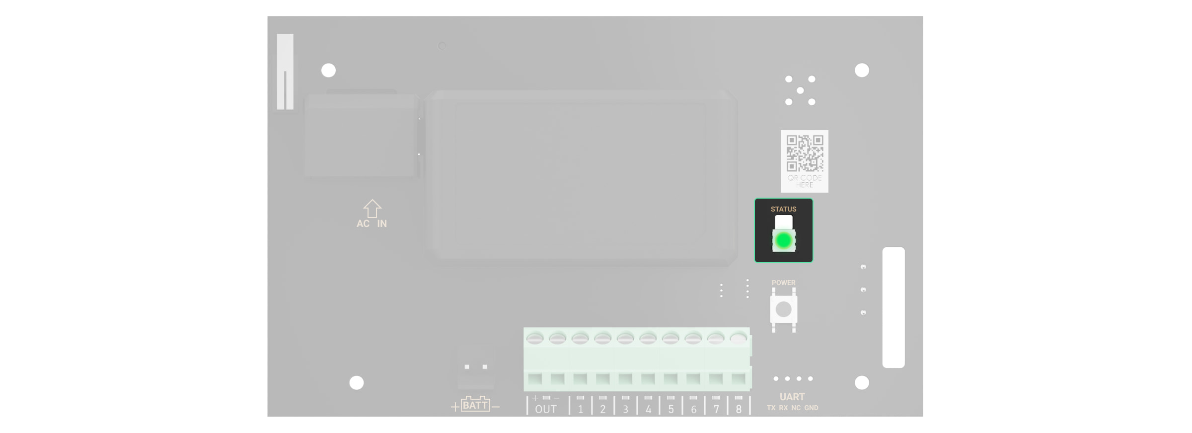
States
1. Install the . Create Add a hub to the app and
create at least one virtual room.
Ajax PRO app an account.
2. Check that the hub is on and has access to the Internet:via Ethernet cable,
Wi-Fi, and/or mobile network. You can do this in the Ajax app or by checking
the hub logo on the faceplate. It should light up white or green if the hub is
connected to the network.
3. Check the status of the hub in the Ajax app and make sure that it is
disarmed and does not start updates.
We value your privacy
We use cookies to enhance your browsing experience, serve personalized ads or content, and analyze our trac. By
clicking "Accept All", you consent to our use of cookies.Cookie Policy

To connect vhfBridge
Please note that to nd and pair the device, the transponder should be located within the
hub’s radio communication range (on the same secured premises).
If the connection has failed, disconnect vhfBridge for 5seconds and try again. If
the transponder has already been assigned to another hub, turn off vhfBridge
and then follow the standard addition procedure.
The connected transponder will appear in the list of hub devices in the app.
Device status updates depend on settings. The default status update
period in the app is 36seconds.
Malfunction counter
1. Open the Ajax app. If your account has access to multiple hubs, select the
one to which you want to add vhfBridge.
2. Go to the Devices menu and click Add Device.
3. Name the transponder, scan or enter the QR code manually (located on the
device casing and packaging), and select a room and a group (if the group
mode is activated).
4. Click Add — the countdown will begin.
5. Switch on vhfBridge by holding the power button for 3seconds. Keep in
mind that the hub connection request is only sent when the integration
module is turning on.
Jeweller
We value your privacy
We use cookies to enhance your browsing experience, serve personalized ads or content, and analyze our trac. By
clicking "Accept All", you consent to our use of cookies.Cookie Policy

When a vhfBridge malfunction is detected (e.g., no external power), the Ajax app
will display a red icon with a number in the upper left corner of the device icon.
This number indicates the number of malfunctions.
All malfunctions can be seen in the transponder states. Fields with malfunctions
will be highlighted in red.
Icons
Icons display some of the vhfBridge states. You can check them in the Ajax app
in the Devices tab.
We value your privacy
We use cookies to enhance your browsing experience, serve personalized ads or content, and analyze our trac. By
clicking "Accept All", you consent to our use of cookies.Cookie Policy

Icon Meaning
Jeweller Signal Strength. Displays the signal strength between the hub and
vhfBridge.
Recommended value is 2–3 bars.
The charge level of the battery connected to vhfBridge.
Is displayed when vhfBridge is operating via a
.
vhfBridge is disabled.
vhfBridge tamper triggering events are disabled.
States
States can be found in theAjaxapp:
Parameter Meaning
Malfunction
Click to open the list of vhfBridge
malfunctions.
The eld is displayed only if a battery charge
malfunction is detected.
Jeweller Signal Strength Signal strength between the hub and vhfBridge.
radio signal range
extender
Learn more
Learn more
1. Go to the Devices tab.
2. Select vhfBridge from the list.
We value your privacy
We use cookies to enhance your browsing experience, serve personalized ads or content, and analyze our trac. By
clicking "Accept All", you consent to our use of cookies.Cookie Policy

Recommended value is 2–3 bars.
Connection via Jeweller
Connection status between the hub and
vhfBridge:
Battery Charge
Battery charge level of the device. Displayed as
a percentage.
Also, this eld can display the battery status:
Lid
The status of tampers that respond to
detachment or violation of the integrity of the
casing.
External Power
The presence of the 100–240 V~ external
power supply:
Name of ReX range extender Radio signal range extender connection status:
Please note that the eld is displayed if
vhfBridge is operated via a
Online — the device is connected.
Oine — the device is not connected.
How battery charge is displayed in
Ajax apps
Charging— the battery is charging.
Error— the battery has been charging for
more than 40hours.
What is tamper
Connected — the external power is
connected.
Disconnected — the external power is
disconnected.
Online — the device is connected.
Oine — the device is not connected.
radio signal
We value your privacy
We use cookies to enhance your browsing experience, serve personalized ads or content, and analyze our trac. By
clicking "Accept All", you consent to our use of cookies.Cookie Policy

.
Permanent Deactivation
Shows the status of the device permanent
deactivation function:
Firmware vhfBridge rmware version.
Device ID vhfBridge ID/serial number. Also located on the
device box, its board, and the casing.
Device No. Device loop (zone) number.
vhfBridge settings
Settings can be changed in the Ajax app:
range extender
No — the device operates in normal mode
and transmits all events.
Lid only— the hub admin disabled
notications about tamper alarms.
Entirely — the device is completely excluded
from the system operation by the hub
admin. The device does not follow system
commands and does not report alarms or
other events.
We value your privacy
We use cookies to enhance your browsing experience, serve personalized ads or content, and analyze our trac. By
clicking "Accept All", you consent to our use of cookies.Cookie Policy

Please note that after editing the settings, you should click the Back button to save
them.
Conguration Meaning
Name
vhfBridge name. Displayed in the text of SMS
and notications in the event feed.
To change the device name, click on the pencil
icon.
The name can contain up to 12Cyrillic
characters or up to 24 Latin characters.
Room
Selecting the virtual room to which vhfBridge is
assigned.
The room name is displayed in the text of SMS
and notications in the event feed.
Track battery charge time
Set up the battery charge duration.
When this option is enabled, the system will
send a malfunction notication if the battery
connected to vhfBridge has been charging more
than 40 hours.
Disable tracking if the VHF transmitter is
powered directly from the battery and not from
the vhfBridge power terminals.
Pulse Duration, sec Pulse time on an event (from 1 to 255 seconds).
Set in increment of 1 second.
1. Go to the Devices tab.
2. Select vhfBridge from the list.
3. Go to Settings by clicking the icon in the upper right corner.
4. Set the parameters.
5. Click Back to save the new settings.
We value your privacy
We use cookies to enhance your browsing experience, serve personalized ads or content, and analyze our trac. By
clicking "Accept All", you consent to our use of cookies.Cookie Policy

The default value is 5 seconds.
Jeweller Signal Strength Test
Switches vhfBridge to the Jeweller signal
strength test mode.
The test allows you to check the signal strength
between the hub and vhfBridge and determine
the optimal installation location.
Permanent Deactivation
Allows the user to disable the device without
removing it from the system.
Three options are available:
User Guide Opens vhfBridge User Guide in the Ajax app.
Unpair Device Unpairs vhfBridge, disconnects it from the hub,
and deletes its settings.
vhfBridge output conguration
By default, vhfBridge outputs are congured as follows:
What is Jeweller Signal Strength
Test?
No — the device operates in normal mode
and transmits all events.
Entirely— the device will not execute
system commands or participate in
automation scenarios, and the system will
ignore device alarms and other notications.
Lid only — the system will ignore
notications about the triggering of the
device tamper only.
Learn more about permanent
deactivation of devices
1st output— intrusion
2nd output— panic button
We value your privacy
We use cookies to enhance your browsing experience, serve personalized ads or content, and analyze our trac. By
clicking "Accept All", you consent to our use of cookies.Cookie Policy

The settings of outputs can be changed in the Ajax app:
Conguration Meaning
Type of Event
Selection of the event type to which vhfBridge
output reacts.
Check the complete list of event types and their
icons .
Connection type
Selection of the output type:
Event types of vhfBridge outputs
3rd output— malfunction
4th output— tamper
5th output — loss of vhfBridge power supply
6th output— power loss of the hub
7th output— hub battery discharged
8th output — loss of communication between the hub and vhfBridge
1. Go to the Devices tab.
2. Find vhfBridge in the list of devices.
3. Go to the Outputs menu.
4. Find the output in the list and go to its Settings by clicking the gear icon .
5. Set the parameters.
6. Click Back to save the new settings.
below
High potential output (positive trip).
Low potential output (negative trip).
We value your privacy
We use cookies to enhance your browsing experience, serve personalized ads or content, and analyze our trac. By
clicking "Accept All", you consent to our use of cookies.Cookie Policy

Icon Type of event Operating
mode Description
Not assigned No Output disabled.
Intrusion Pulse Alarm when motion, opening, and other
detectors are triggered.
Fire Pulse Alarm when re detectors are triggered.
Auxiliary
alarm Pulse Alarm when pressing the auxiliary request alert
button.
Panic button Pulse Alarm by clicking:
DoubleButton
in panic button modeButton
The panic button on the SpaceControl
key fob
The panic button connected to the
or Transmitter MultiTransmitter
The functional button of
when it operates in panic button mode
Ajax keypads
We value your privacy
We use cookies to enhance your browsing experience, serve personalized ads or content, and analyze our trac. By
clicking "Accept All", you consent to our use of cookies.Cookie Policy

Any alarm Pulse Alarm of any connected detector.
Malfunction Pulse Any malfunction of the connected detectors.
Transponder
external
power failure
Bistable Loss of external 110–240 V~ power supply to
vhfBridge transponder.
Transponder
battery low Bistable vhfBridge backup battery is discharged.
Hub external
power failure Bistable Loss of external 110–240 V~ power supply to
the hub.
Hub battery
low Bistable Hub backup battery is discharged.
The virtual panic button in Ajax apps
We value your privacy
We use cookies to enhance your browsing experience, serve personalized ads or content, and analyze our trac. By
clicking "Accept All", you consent to our use of cookies.Cookie Policy

Lid Pulse Triggering of tamper of any device in the
system.
Security
mode change Bistable Changing the security mode of an object or
group.
Conrmed
intrusion
alarm
Pulse Conrmed alarm according to
.
Conrmed
hold-up
alarm
Pulse Conrmed hold-up device alarm according to
.
Hub-
transponder
connection
loss
Bistable
Loss of vhfBridge connection with the hub /
radio signal range extender via Jeweller
channel.
The time before sending an event regarding the loss of communication between the hub
and vhfBridge to the CMS is calculated with the following formula:
“Hub — detector” polling interval × 30 undelivered packets.
With the minimum values of the “hub — detector” polling interval, an event regarding the
loss of communication with the hub is sent to the CMS in 6 minutes.
PD
6662:2017
PD 6662:2017
We value your privacy
We use cookies to enhance your browsing experience, serve personalized ads or content, and analyze our trac. By
clicking "Accept All", you consent to our use of cookies.Cookie Policy

Connecting VHF transmitter to vhfBridge
List of recommended VHF transmitters
vhfBridge can be connected to any VHF transmitter with relay inputs. Connection via
UART, RS-485, and other interfaces is not supported.
How to connect a VHF transmitter to vhfBridge
When connecting the VHF transmitter, do not twist the wires together, but solder them.
The ends of the VHF transmitter wires, which will be inserted into the vhfBridge
terminals should be tinned or crimped with a special sleeve.
Hawk VHF Alarm Transmitter (FSK Electronics)
TX750C (RDC)
TR-41 (Puper)
1. Turn off the vhfBridge power (if power was connected).
2. Turn off vhfBridge.
3. Select vhfBridge outputs to which you want to connect the VHF transmitter.
4. Pull the VHF transmitter wires into the vhfBridge casing through the holes.
There are perforated sections on the casing that can be broken off so that the cable
could be pulled through them.
5. Connect the VHF transmitter to the control outputs of vhfBridge according
to the wiring diagram in the User Guide supplied by the VHF transmitter
manufacturer.
We value your privacy
We use cookies to enhance your browsing experience, serve personalized ads or content, and analyze our trac. By
clicking "Accept All", you consent to our use of cookies.Cookie Policy
Other manuals for vhfBridge
2
This manual suits for next models
1
Table of contents
Other AJAX Transmitter manuals
Popular Transmitter manuals by other brands

SICK
SICK PFT operating instructions

Monarch
Monarch 295SEPC1K manual

Technisonic Industries Limited
Technisonic Industries Limited TiL-92-SC Installation and operating instructions

Solartron Mobrey
Solartron Mobrey 7828 Technical manual

nedis
nedis BTTC200BK quick start guide

JUMO
JUMO CTI-750 operating manual

Hama
Hama AT-802 Operating instruction

RKI Instruments
RKI Instruments 65-2645RK-05-04 Operator's manual

Superior Broadcast
Superior Broadcast SBFM1000SS user manual

turck
turck IM31-12Ex-i U Series quick start guide

Mil-Ram Technology, Inc.
Mil-Ram Technology, Inc. TA-2102 instruction manual

Intellinet
Intellinet 561211 Quick instruction guide