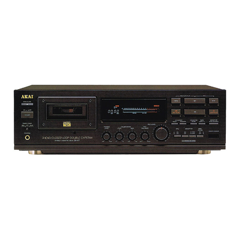
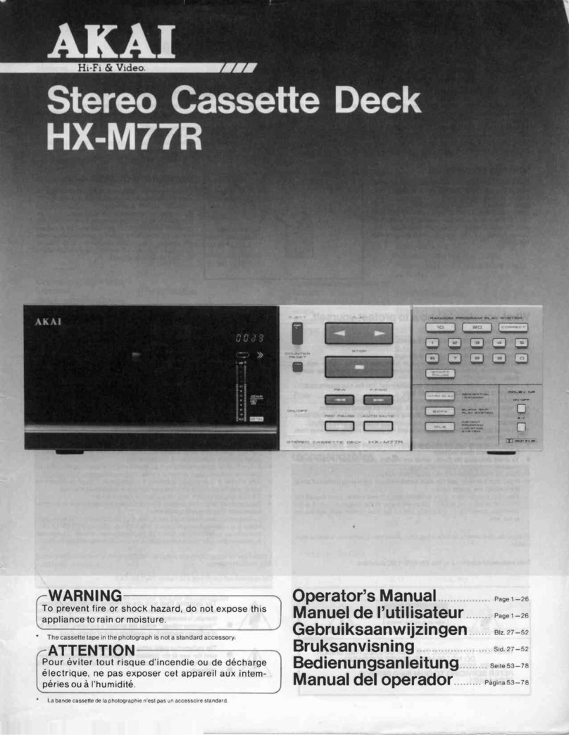
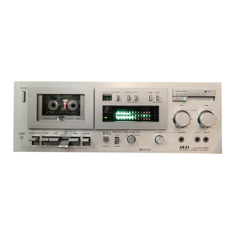
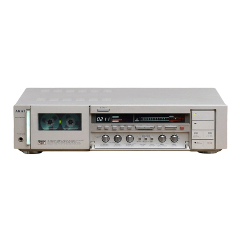
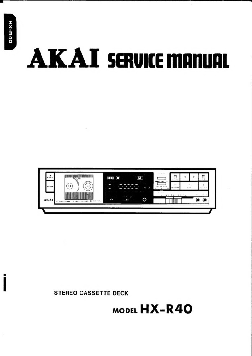
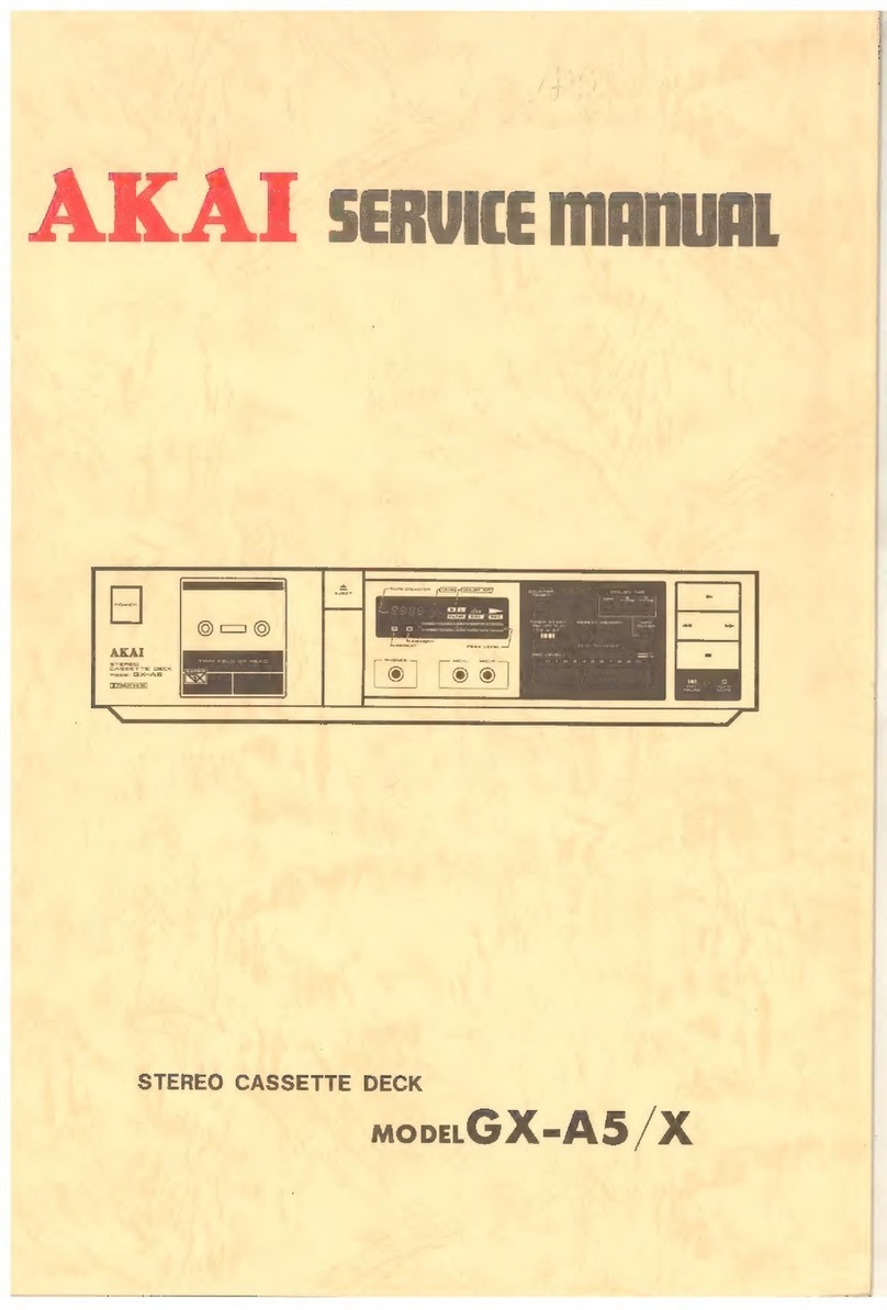
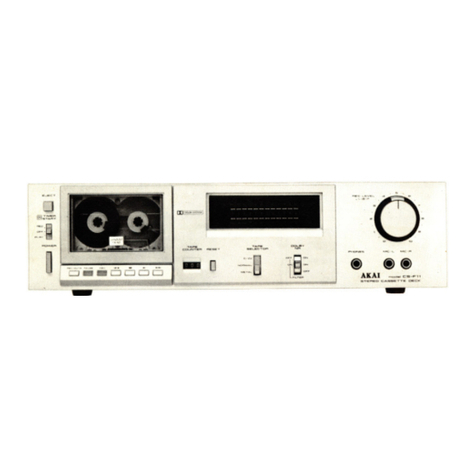
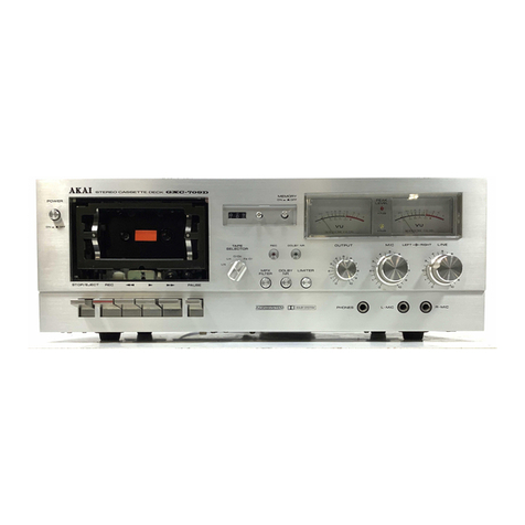
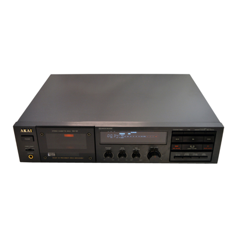
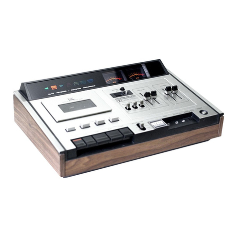
Akai HX-RS User manual

■
AKAi
I
STEREO CASSETTE DECK
I
MODEL
HX-RS
MODELGX-R6

----
ABBREVIATIONS FOR SERVICE
MANUAL
MODEL HX-R5/GX-R6
ABBREVIATIONS
EXPLANATION
AC Alternating Current
ADJ ADJust
ALU Arithmetic and Logic Unit
A-SW Analogue SWitch
BSS
Blank Search System
DET
DETector
EQ EQualizer
EXT
EXTernal
FF Fast Forward
FLO FLuorescent Display
FREQ FREQuency
FWD ForWarD
GND
GrouND
'"H'' High (referring to voltage)
HLS High Level Stage
INH INHibit
IPLS Instant Programme Locating System
LLS Low Level Stage
MIC
MI
Crophone
NR
Noise Reduction
osc OSCillator
RL ReLay
REC RECord
REF REFerence
REV REVerse
REW REWind
RWD ReWinD
SEL SELect
SENS SENSitivity
XTAL
CrysTAL

STEREO CASSETTE DECK
MODEL HX-R5
STEREO CASSETTE DECK
MODEL GX-R6
SECTION
1 SERVICE MANUAL............................................... 3
SECTION 2 PARTS LIST............................................................ 35
SECTION 3 SCHEMATIC DIAGRAM ...................................... 53
-----------SERVICE
MANUAL
HX-R5/GX-R6-----------

SAFETY
INSTRUCTIONS
SAFETY CHECK AFTER SERVICING
Confirm the specified insulation resistance between power cord plug prongs and externally exposed parts
of
the set
is
greater than
10
Mohms, but for equipment with external antenna terminals (tuner, receiver, etc.) and
is
intended for
[g
or
[Al,
specified insulation resistance should be more than 2.2 Mohms (ground terminals, microphone jacks, headphone
jacks, line-in outjacks etc.).
PRECAUTIONS DURING SERVICING
I. Parts identified by the
Lt
symbol parts are critical for safety.
Replace only with parts number specified.
2.
In addition to safety, other parts and assemblies are specified for conformance with such regulations as those apply-
ing to spurious radiation. These must also be replaced only with specified replacements.
Examples: RF converters, tuner units, antenna selector switches,
RF
cables, noise blocking capacitors, noise block-
ing filters, etc.
3.
Use specified internal wiring. Note especially:
I) Wires covered with PVC tubing
2)
Double insulated wires
3)
High voltage leads
4.
Use specified insulating materials for hazardous live parts. Note especially:
I) Insulation Tape
2) PVC tubing
3) Spacers (Insulating Barriers)
4)
Insulation sheets for transistors
5)
Plastic screws for fixing microswitch (especially in turntable)
5.
When replacing AC primary side components (transformers, power cords, noise blocking capacitors, etc.), wrap
ends
of
wires securely about the terminals before soldering.
6.
Observe that wires do not contact heat producing parts (heatsinks, oxide metal film resistors, fusible resistors, etc.).
7.
Check that replaced wires do not contact sharp edged
or
pointed parts.
8. Also check areas surrounding repaired locations.
9. Use care that foreign objects (screws, solder droplets, etc.) do not remain inside the set.
10. Voltage Conversion
l)
Models for Japan, Canada, USA, Europe,
UK
and Australia are not equipped with this facility.
Each machine
is
preset at the factory according to destination, but some machines can be set to l
IOV,
120V,
220V
or
240V as required.
IfVoltage conversion on your machine
is
possible,
1-1)
Disconnect power cord.
1-2)
Turn
the VOLTAGE SELECTOR located on the rear panel with a screwdriver until the correct voltage is
indicated.
2) Cycle Conversion
Cycle conversion
is
not necessary since HX-R5 and
GX-R6
uses DC motors.
---------------SERVICE
MANUAL
HX-R5/GX-R6---------------
2

SECTION
1
SERVICE
MANUAL
TABLE OF CONTENTS
I. SPECIFICATIONS ........................................................................... 4
II. DISMANTLING OF UNIT ............................................................. 6
III. CONTROLS..................................................................................... 7
IV. PRINCIPAL PARTS LOCATION................................................... 8
V.
CIRCUIT OPERATION DESCRIPTION....................................... 9
I. PRE-AMP BLOCK DIAGRAM................................................... 9
2.
SYSCON BLOCK
DIAGRAM
AND
THE
PERIPHERAL
CIRCUIT.......................................................................................
10
3.
ELECTRONIC VOLUME ............................................................
11
VI. MECHANICAL DESCRIPTION OF EACH MODEL ....................
13
I. DESCRIPTION
OF
THE
MECHANISM DRIVEN
BY
CAM WHEELS
(L)
& (R) ........................................................
13
VII. ME(HANICAL ADJUSTMENT.................................................... 18
I. PINCH ROLLER PRESSURE MEASUREMENTS .....................
18
2.
WINDING
TORQUE
MEASUREMENT
IN EACH
MODE...........................................................................................
18
3. TAPE SPEED
ADJUSTMENT
....................................................
18
VIII. HEAD ADJUSTMENT ................................................................... 19
I. TAPE
GUIDE
ADJUSTMENT
.................................................... 20
2. REC/PB HEAD
AZIMUTH
ADJUSTMENT
.............................. 20
3.
HEAD
HEIGHT
ADJUSTMENT
................................................ 20
4.
HEAD BLOCK
PROJECTION
ADJUSTMENT
......................... 20
IX.
ELECTRICAL ADJUSTMENT.......................................................
21
I. SYSCON P.C BOARD
ADJUSTMENT
.......................................
21
2. PRE-AMP P.C BOARD
ADJUSTMENT
.....................................
22
X.
DC
RESISTANCE OF HEAD.......................................................... 24
XI. CLASSIFICATION OF VARIOUS P.C BOARDS ......................... 24
I. P.C BOARD TITLES
AND
IDENTIFICATION
NUMBERS.................................................................................... 24
2.
COMPOSITION
OF
VARIOUS P.C BOARDS ............................
25
-------------SERVICE
MANUAL
HX-R5/GX-R6-------------
3

I.
SPECIFICATIONS
1-1. MODEL HX-R5
Track system 4
Track
2 Channel stereo system
Tape
Philips type cassette
Heads Erase Hea'd x 1
High Density for
REC/PB
x 1
Motors Electronically speed controlled
DC
motor
for capstan drive x 1
DC
motor
for
cam
drive x 1
Wow & Flutter 0.12% (DIN)
0.04% (W. RMS)
±0.07%
W.
PEAK
(EIAJ)
Frequency Response NORMAL: 20 to 15,000
Hz
± 3 dB
(-20
VU)
CrO2: 20 to 16,000
Hz
±3
dB
(-20
VU)
METAL:
20 to 17,000
Hz
± 3 dB
(-20
VU)
SIN
58
dB
55
dB (EIAJ)
DOLBY
BON:
Improves
up
to
5 dB
at
1 kHz
10 dB above 5
kHz
DOLBY
CON:
Improves
up
to
15
dB
at
500 Hz
20 dB
at
1
kHz
to 10
kHz
Distortion 0.
7%
(MET
AL)
Input LINE: 70
mV/47
kohms
MIC: 2.5
mV/5
kohms
Output
LINE: 410 mV/1 kohms
PHONE:
1.3
mW/8
ohms
Power Requirements IO0V,
50/60
Hz
for
Japan
120V,
60
Hz
for
USA
and
Canada
220V, 50 Hz for Europe except
UK
240V,
SO
Hz for
UK
and
Australia
110V/120V/220V
/240V,
50/60
Hz switchable for
other
coun-
tries
Power Consumption JPN: 18W
CSA,AAL:
18W
UT:
18W
Dimensions 440 (W) x 105 (H) x 288 (D)
mm
(17
.3
x 4.1 x 11.3 inches)
Weight 4.7
kg(I0.3
lbs)
*
For
improvement purposes, specifications
and
design are subject to change without notice.
* Noise reduction manufactured
under
license from Dolby Laboratories Licensing Corporation.
"Dolby"
and
the
Dou-
ble-O
symbol are trade marks
of
Dolby Laboratories Licensing Corporation.
----------------~ERVICE
MANUAL
HX-RS----------------
4

1-2. MODEL GX-R6
Track
system 4
Track
2
Channel
stereo system
Tape
Philips
type cassette
Heads Erase
Head
x 1
Twin
Field
super
GX
head for
REC/PB
x I
Motors Electronically speed
controlled
DC
motor
for
capstan
drive x I
DC
motor
for
cam
drive x I
Wow &
Flutter
0.12% (DIN)
0.04% (W. RMS)
±0.07%
W.
PEAK(EIAJ)
Frequency Response NORMAL:
20to17,000Hz±3dB
\-20VU)
CrO2: 20
to
18,000
Hz
± 3 dB
(-20VU)
METAL:
20
to
19,000
Hz
± 3 dB
(-20VU)
SIN
58 dB
55 dB (EIAJ)
DOLBY
BON:
Improves
up
to
5 dB
at
I kHz
IO
dB above 5 kHz
DOLBY
CON:
Improves
up
to
15
dB
at
500
Hz
20
dB
at
I
kHz
to
10 kHz
Distortion 0.
7%
(MET
AL)
Input LINE: 70
mV/47
kohms
MIC:
2.5
mV/5
kohms
Output
LINE:
410
mV/1
kohms
PHONE: 1.3
mW
/8
ohms
Power Requirements I00V,
50/60
Hz
for
Japan
120V, 60
Hz
for
USA
and
Canada
220V, 50
Hz
for
Europe
except
UK
240V,
50Hz
for
UK
and
Australia
I
IOV/120V/220V/240V,
50/60
Hz switchable for
other
coun-
tries
Power
Consumption
JPN: 16W
CSA,AAL:
17W
UT:
17W
Dimensions
440
(W) x 105 (H) x 288 (D)
mm
(17
.3
x 4.1 x 11.3 inches)
Weight 4.7
kg
(I0.3 lbs)
*
For
improvement
purposes, specifications
and
design are subject
to
change
without
notice.
* Noise reduction manufactured
under
license from
Dolby
Laboratories Licensing Corporation.
"Dolby"
and
the
Dou-
ble-D symbol are trade
marks
of
Dolby
Laboratories Licensing
Corporation.
----------------SERVICE
MANUAL
GX-R.n-----------------

II.
DISMANTLING
OF
UNIT
In
case oftrouble, etc. necessitating dismantling, please dismantle in the order shown in the photographs.
Reassemble
in
reverse order.
2
3
j
; I
! l
b-,'®I
a
SCREWS
UPPER
COVER
'
,,,.,..
...
..,
..
~..,.,,
-- -
"'
-·""""'""'
~......
~
~'"•---•"'
"'\~t;,!OCUJ,ru
-
~
~
~ -
~
~
,,,
.;;:::
..
~
""
-""
-·-
_JL
b
.
~o
~~
.
l~I
"""
··="'
SCREWS
4
S.CREWS
5 b
SCREWS
6
---------------SERVICE
MANUAL
HX-R5/GX-R6--------------
6

Ill.
CONTROLS
Fig.
3-1
Front View
Fig. 3-2 Rear View
1.
POWER SWITCH 16.
REC
LEVEL CONTROL
2. CASSETTE HOLDER 17. DIGITAL COUNTER
3. EJECT BUTTON 18. IPLS INDICATOR
4. OPERATION BUTTONS 19. DOLBY B/C INDICATORS
5.
CONTAINS
JACKS
FOR
MIC L/R
AND
HEADPHONE
20.
MPX
FILTER INDICATOR (GX-R6 ONLY)
6. OUTPUT/PHONES CONTROL (GX-R6 ONLY) 21. TAPE (NORMAL, Cr02, METAL) INDICATORS
7.
TIMER START SELECTOR
22.
REC
LEVEL POSITION INDICATOR
8.
RESET BUTTON
FOR
DIGITAL COUNTER 23. REC/P.B LEVEL INDICATORS
9.
IPLS BUTTON 24.
REV
SELECTOR
AND
DIRECTION INDICATORS
10.
REV
SELECTOR
25.
REMOTE CONTROL
JACK
11. INTRO SCAN BUTTON (GX-R6 ONLY)
26.
LINE
IN
(L/R)
JACKS
12. BLANK SEARCH BUTTON (GX-R6 ONLY)
27.
LINE OUT (L/R)
JACKS
13. DOLBY
NR
SWITCH
AND
SELECTOR
28.
VOLTAGE SELECTOR (
[Q])
model
only
14.
REC
CANCEL BUTTON (GX-R6 ONLY) 29. AC POWER CORD
15.
MPX
FILTER SWITCH (GX-R6 ONLY)
--------------SERVICE
MANUAL
HX-RS/GX-R6,--------------
7

IV.
PRINCIPAL
PARTS
LOCATION
POWER
SWITCH
CAM DIRECTION
SW905
HOUSING PCB
CMROID1430
GUIDE
DETECTOR PCB
CMROID0220
POWER
TRANSFORMAR
T901
POWER
SWITCH
CONTROL
PCB
CMROIC189A
CAM
MOTOR
RD-IBOS
REC/PB
AND
___
~
ERASE HEAD
LEAF
SWITCH PCB
CMROIC1490
CAM
MOTOR
PULSE
PCB
CMROICIB9B
TIMER START (SW19)
OFF/
PLAY/
REC
EJECT
SW902
,-ouTPUTPcs7
I
T2045A501C
1
Lo~T_f'_U:1:...
~Ll:l_Mi
~
GX-R6
ONLY
CAPSTAN
MOTOR
EG-510ED-2B2
COUNTER
RESET(SW15)
DOLBY
NR
ON/OFF(SW16)
B / C (SW17)
~MPXFILTTRtSWISl]
~
~C~C~N~E~(~w19>_j
GX-R6
ONLY
Fig.
4-1 Front View
LINE
IN,OUT
JACKS REMOTE JACK
Fig. 4-2 Top View
---------------SERVICEMANUALHX-RS/GX-R.b---------------
8

V.
CIRCUIT
OPERATION
DESCRIPTION
5-1.
PRE-AMP
BLOCK
DIAGRAM
UP
~
___________________________
o_o_w--<N
8:P,
MIC
INr~------
IC
I M5218L
r--
--
--,
I
re
11
I
3
MIC/LINE
~-~
I I
ELECTRONIC
I I
2 AMP VOLUME
SW
IN MIC JACK
IC4
LC7530
L
________
...J
SYSCON
PCB
LINE
OUT~---+-----------..--------'
METER
OUT
(TO
SYSCON)
TR3
2SC2320
(
I
I
/
/
I /
~/
PB
MUTE
TR26to28
PB
AMP
I
RL
I
I
.--....;...
__
_
L_____
REC/PBS
RELAY
TR26
2SCl843
TR27 2SCl312S
TR28
2SC2320
TR29
2SC2603
!5
9
IC3
NE654
DOLBY
SWITCHING
IC
IC2
NE652
DOLBY
IC
IC5
LA6458S
IPLS
AMP
TR22,23
2SC2603
BIAS
osc
C77
,
REC
LEVEL
IC4
LA6458S---(GX-R6)
TR?
2SC2320---(HX-R5)
TR8tol3
2SC2320
REC
AMP
TR6 2S01012
REC
MUTE
BIAS
TRAP
REC
MUTE
P.
B MUTE
DOLBY
SW
OFF/B/C
IPLS
OUT
REC/PB
SW
L..-----------------{
1
OSC
ON/OFF
Cr02
BIAS
METAL DET
Fig.
5-1
Block Diagram
of
Pre-Amp P.C Board
z
0
u
en
>-
en
0
I-
-------------------------------SERVICEMANUALHX-R5/GX-R6;-------------------------------
9

5-2. SYSCON BLOCK DIAGRAM
AND
THE PERIPHERAL CIRCUIT
INPUT
EXPANDER
+5V
SW902 EJECT
SW5 STOP
SW
I
FWD
SW2
REV
SW6
REC
SW3
FF
SW4
REW
SW?
AUTO
MUTE
,-----------,
1SWIO
REC
CANCEL!
TIMER
PCB
1
sw12
INTRO SCAN:
(GX-R6
ONLY)
~
~WJ
!_
_B~S
___
--~
SW
13
REV
SELECTORc
>------iM
SWl4
IPLS
SW
15
COUNTER
RESETu---------___.
SW905
SW901
INPUT
EXPANDER
CAM
DIRECTION
u-----;,.i
FWD/REV
SW906
LEAF
SW
PCB
[
SW903
ANTI
REC
(RWD)u------;;,"ls
ANTI
REC
(REV)C>------eM
SW904
SW907
METER
PCB
SWl9
Cr02
METAL
[
REC
TIMER PLAY
TR2,3
POWER
SUPPLY
PH2
CAM
MOTOR
PULSE
PCB
TRI,
IC9
POWER
OFF
DETECT
*IC2 LB1290
.--..,.....-~-~-~
FLO
DRIVER
G5
64
- - -
...l..
I I I I LI
t/
g
/b
*
IC3,4
LBl290
FLO
I I I I
C.I
•Qc
DRIVER
FLO
(IN
I)
MUSIC
INTERVAL
DET
TR22,23,
IC5
ON
PRE AMP
*
IC2,3,4
ARE
LOCATED
ON
METER
PCB
TPI
QUICK
REV
IE----1
DET GUIDE
DET
PCB
TRIOtol3
TR901,D901
IC I
"'
N
~
2
0
"'
IL
I-
:::,
IL
~
~
0
I-
:::,
IL
I-
:::,
0
!::
(!)
0
IIJ
>
"'
0
I-
z
IIJ
2
(!)
IIJ
(I)
XI
(O.BMHzl
CERAMIC
osc
LM-6402H-190
EX TAL
+5V
PRE
AMP PCB
REC/PB
SW
:>o-+-----------H--ir
REC/PB
sw
7
L....~~TR~
__J
OSC
CONTROL
9
l}----t------t------------t-+tr
osccoNTROL
7
L -
...:!:_R2_~
_ __J
PB
MUTE
r-PBMUTE-
7
x:~-----------------1....-
TR3
I
L
_____
...J
REC
MUTE
7
'REC
MUTE--,
:>o--+------------f~
TR6
I
CAM
MODE
STOP
DET
INPUT
TR902
DETECTOR
(AHBl
PCB
L
_____
...J
CAM
DIRECTION
DET
INPUT
,IE--------P_H---1
3
CAM
DIRECTION
REEL
ROTATION
PULSE
INPUT
EXT
CONTROL
OUTPUT
NORMAL
2
Cr02
31
METAL
I-
:::,
IL
FWD
I-
:::,
0
>-
C[
...I
IL
REV
(I)
0
z
0
.:::
C[
"'
IIJ
IL
0
IPLS
IC?
CAM
MOTOR
CONTROL
REVERSE~~--~
IC5
BA6109
PCB
FLO
!IN
ll
.r-t-
➔
-tONCE
REV
r--1--
➔
--tCONTI
REV
~~RR~~Lj
Cr02
!TR6l
METAL
(TR?
l
IC6
LBl290
IC7,8
LC4049B
CAM
MOTOR
M901
PRE
AMP
PCB
Fig. 5-2 Block Diagram ofSyscon P.C Board
--------------------------------------SERVICEMANUALHX-RS/GX-R.o---------------------------------------
10

5-3. ELECTRONIC VOLUME
LB
1290
LC7530
...J
w
>
w
...J
l)
w
DOWN
11
Ct:
Cs
SIG I
Model HX-R5, GX-R6 employs Electronic Volume in-
stead of Mechanical REC Volume,
and
uses an IC
(LC7530) for both channels.
05
UP -
~
u
02;:l
,
TR9
L
INPUT
L
OUTPUT
R41
+14V
Fig.
5-3
---------------SERVICEMANUALHX-RS/GX-R.o---------------
11

Pin No. Symbol Description
I
INDI
Attenuation
IND
1 REC Level Indicator Drive Terminal Step 8 7 6 5 4 3 2 I
8
IND8
0 -
I H
--
2 H H
-
3 H
-
f--
4 H H
--
5 H
-
f------
6 H H
-
~
7 H
--
8 H H
--
9 H
--
10
H H
--
II H
--
12
H H
-
f--
13
H
~
-
14
H H
f------
-
15
H
9 SIG2
RCH
Signal Input Terminal.
IO
COM2
RCHSignal
Output
Terminal.
Attenuation Attenuation
13
COMI
LCH Signal
Output
Terminal. Step (dB)
14
SIGI LCH Signal Input Terminal. 0 0
A-sw1,
I
-1.0
SIG-
--_
COM
2
-2.0
~;,
3
-3.4
A-SW14 4 -5.1
~
0--
5 -7.1
I 6 -9.3
I 7
-11.7
I 8 -14.1
I 9
-16.5
.,,
:d
10
-18.8
tl
1
11
-21.1
12
-24.5
13
-28.8
14
-34.0
-'
A-SWO
15
-80.0
VM
~
This
attenuator
shown above
is
made up
of
diffused resistors R (50 kohms)
and
analogue
switches (SW0
~
15),
and
it attenuates 0 dB to 80 dB in
16
steps (step
Oto
15).
11
Vss
Center
Bias Terminal.
Connected to the ground
of
signal line.
12
VEE
Connected to ground.
15
cs Back-up Control Terminal. Back-up mode
at
"L".
--
16
INT
Attenuator
(step 9) Set
Up
Terminal, active at
"L".
17
DOWN
Attenuator
Control Signal Input Terminal.
(Increases attenuation)
-
18
UP
Attenuator
Control Signal Input Terminal.
(Decreases attenuation)
DOWN
......
Becoming
"L"
level at this terminal activates the internal oscillator, and
Attenuation
is
increased
one
step each time
at
the rising edge
of
oscillation wave.
Keeping this terminal at
"L"
level continues
attenuation
rise until
the
attenuation rise and
oscillation stop
at
the sixteenth step. (Attenuation
of80
dB)
-
UP
......
Attenuation decreases in the same
manner
as above.
19
CR
Capacitor
and Resistor
Terminal
for Internal Clock Oscillator.
20
Yoo
Power Supply Terminal (+20V).
Chart
I
----------------SERVICE
MANUAL
HX-R5/GX-R6---------------
l2

VI.
MECHANICAL
DESCRIPTION
PART
FOR
EACH
MODE
6-1. DESCRIPTION
OF
THE
MECHANISM
DRIVEN
BY CAM
WHEELS
(L) & (R)
CAM
MOTOR
PULLEY
CAM
SLIT
PHOTO
SENSOR A (
PH2)
PHOTO SENSOR B
(PH3)
0
' /
-r
I
CAM
WHEEL
(L)
LED
(D9O2)
(Located
on
DETECTOR
(Bl
PCB
FAN-
SHAPED HOLE
~
--
~',
,'
\
/)
'
0 J
-'r-il
,'
-/
~--
CAM
WHEEL (R)
SW
LEAF
MODE
(CAM DIRECTION
SW
SW9O5)
Fig. 6-1
Cam
Wheels
(L) & (R) Drive
Mechanism
(Front
View)
Cam
Motor
Pulse
Input
(IC I pin (6))
Cam
Direction
Detection
Input
(IC I pin (3j )
6-1-1.
The
sequence
of
this
transmission
is as follows.
(Refer to Fig. 6-1)
CAM
MOTOR
....
BELT
CAM
....
PULLEY
CAM
SLIT
....
CAM
WHEEL
(L)
....
CAM
WHEEL
(R)
6-1-2.
CAM
MOTOR
is driven by IC5 (BA6109)
on
SYSCON
PCB
and
this IC5 is
controlled
by
the
various
control
signals from
various
detectors
and
switches
through
the
action
of
Ml-COM
IC!
(LM6402H-l
90).
6-1-3.
PULLEY
CAM
SLIT
is
driven by BELT
CAM
and
drives
CAM
WHEEL
(L),
and
the
slits
on
PULLEY
CAM
SLIT
are
used for
the
detection
of
CAM
MOTOR
PULSE
and
CAM
DIRECTION.
6-1-4.
CAM
WHEELS
(L)
(R)
contain
grooves to shift 8
mechanical
parts shown in Figs. 6-5 & 6-6, which
exe-
cute
all
the
operations
such
as;
I)
Shifting
Head
block
up
and
down.
2) Shifting
Pinch
Rollers
up
and
down.
3)
Rotation
of
Reel Tables.
4)
Rotation
of
Head
(for
FWD
& REV modes)
H H
IL
:L
I I
I
IH
I I
I I
I I
I
1L
I I
I I I
+I
+I
-1 -1
-,
UP UP
DOWN DOWN
DOWN
Fig. 6-2
6-1-5.
SW
LEAF
MODE
is used for
the
detection
of
the
current
CAM
WHEEL
position.
It
is
"ON"
during
REV
/FF
modes
and
"OFF"
during
FWD/REW
modes
.
6-1-6.
DETECTORS
A,
Bare
usd
for
the
detection
of
STOP
mode.
TR902
is
"ON"
during
STOP
mode.
6-1-7.
PHOTO-SENSOR
A
(PH2)
is used for
the
detec-
tion
of
CAM
MOTOR
PULSES,
and
tog~ther with
PHOTO-SENSOR
B,
its
count
sets
up
the
position
of
the
CAM
WHEELS.
6-1-8.
PHOTO
SENSOR
B
(PH3)
is used for
the
detec-
tion
of
CAM
direction.
That
part
of
the
CAM
MOTOR
PULSE
in
which
the
pulse changes from
"H"
to
"L"
is
used for
counting
up
(+)
and
down(-)
as
indicated
in Fig.
6-2
to
set
up
CAM
WHEELS
(L) & (R).
---------------SERVICE
MANUAL
HX-RS/GX-Rn----------------
13

6-1-9. Mechanical Operations in each mode
LEVER
BRAKE
(L)
IDLER PLAY
ASSY(L)
ARM
RETURN(L)
-----~
ARM
PLAY PART
(L)--~
ARM
HEAD
SHIFT
(L)
_____J
SLIDE
FF---+----:s,..,.
RACK
LEVER
BRAKE
(R)
PLAY (R)
IOLER PLAY ASSY (R)
++-~+-+----RUBBER
PULLEY
~K=7:--r
1
---CAPSTAN
~--
ARM PLAY PART (R)
L__
ARM HEAD
SHIFT
(R)
Fig. 6-3
The
Mechanism for
FWD/REV
Mode
.----------------,----
ARM WIND ASSY
'-~
---t-----
GEAR WIND
(8)
~~.J1
..-
1
~---SLIDE
RWD
ltr
:"""
-;,7.J
I
l,
{1
V.
,..J
P4
~~
,~=-,...~
~-
ARM IDLER
SHIFT(L)---+---
,-,
Fig. 6-4
The
Mechanism for
FF/RWD
(includes IPLS & Intro Scan)
---------------SERVICE
MANUAL
HX-R5/GX-R6,---------------
14

ARM
HEAD SHIFT (R)
-----------~
~-----------ARM
HEAD
SHIFT
(L)
ARM
IDLER
SHIFT
(R)---t+-------Sa>I
HOUSING
ROTARY
PART
GEAR HEAD
RACK
TORSION SPRING ,
HEAD CHASSIS PART
Fig. 6-5
The
Location
of
Arm Head Shift &
Arm
Play (Inside View)
SET
CAM
WHEELS
(L)
a (R)
AS
SHOWN
IN
THIS CIRCLE
1-E----+t------ARM
IDLER
SHIFT(L)
Fig. 6-6
The
Location
of
Arm
Idler Shift &
Arm
Return
(Inside View)
HOLDER
ROTARY
rGEAR
HEAD
\ RACK
~
' I
□~)
Fig. 6-7
The
Bottom View
of
Rotary Head Mechanism
(FWD
Mode)
---------------.°'ERVICEMANUALHX-RS/GX-Ro---------------
15

I) FWD mode (Refer to Fig. 6-3)
Cam Wheels
(L)
& (R) turn clockwise
(L)
and
counter-clockwise (R) for
+91
counts in each direc-
tion, and put
on
the brake for 20m sec. (All the
other modes end with the brake operating for 20m
sec as well.)
The mechanical operations in the meantime are as
follows.
a)
Arm Return
(L)
moves to the right and pushes
· Rack in the same direction so that the Rota-
ry
head turns into the FWD position.
b) Arm Head Shift (L) turns on its pivot ®
so
Part ® moves downwards and Part @ moves
upwards. (Part
®)[pushes
Head Chassis up to
the position for play mode.
pushes Lever Brake (Part
©)
up and release the
brake.
c)
Arm Play (R) turns on its pivot
(§
so
Part
@
moves to the right, and Part ® moves down-
wards and pushes Slide Play (R) down so that
Idler Play Assy (R) moves to the left and trans-
mits the rotation
of
the Capstan to the Take-up
Reel Table.
At the same time,
Arm
Pinch Roller (R) turns
clockwise on its Pivot
®)
and Pinch Roller (R)
comes up for Play mode.
2)
REV mode (Refer to Fig. 6-3)
Cam
Wheels
(L)
& (R)
turn
counter-clockwise
(L)
and clockwise (R) for the same counts as FWD
mode.
The mechanical operations in REV mode can be
obtained from the description
of
FWD mode in
item I) by interchanging left
(L)
and right (R).
3)
FF
mode (Refer to Fig. 6-4)
a) Cam Wheels
(L)
& (R) turn counter-clockwise
(L)
and clockwise (R) for
43
counts and
turn
the
other way (clockwise (L), counter-clockwise (R))
until the count
is
reduced to 25.
b) In
FF
& RWD modes, only
Arm
Idler Shift (L),
(R) are involved.
Arm Idler Shift
(L)
turns on its pivot
(§)
so Part
® moves to the right which pushes the Slide
FF
to the right
--~
Arm Wind Assy moves to
the right, engages Gear
Wind
(B)
and transmits the
rotation
of
Arm
Wind
Assy to Take-up Reel
Table.
,__
___
Pushes Lever Brake (R)
(Part @ ) to release the
brake.
4)
RWD
mode (Refer to Fig. 6-4)
a)
Cam
Wheels
(L)
& (R) turn clockwise
(L)
and
counter-clockwise (R) for the same counts as
FF
mode.
b)
The
mechanical operations in RWD mode can
be obtained from the description
of
the
FF
mode in item
1)
by interchanging left
(L)
and
right (R).
5)
FF
Search
(IPLS,
Intro Scan)
a)
Cam
Wheels
turn
in the same directions as in
FF
mode for
51
counts and for the reduction
of
25
counts.
b)
The
mechanical operations in this mode are the
same as in
FF
mode, except that the
Arm
Head
Shift
(L)
pushes up the Chassis Head
Part
which
raises the Head Block to the
FF
Search mode
position.
6)
RWD Search (IPLS, Intro Scan)
a) Cam Wheels
turn
in the same directions as in
RWD mode for the same counts as in
FF
search
mode.
b)
The mechanical operations in this mode are the
same as in
REW
mode, except that the
Arm
Head Shift (R) pushes up the Chassis Head
Part
which raises the Head Block to the R
WD
Search
mode position.
6-1-10. How to install
Cam
Wheels
(L)
and (R). (Refer
to Fig. 6-6)
Set
Cam
Wheels
(L)
and (R) as indicated in Fig. 6-6.
The color
of
Cam Wheel
(L)
is
black and (R)
is
white,
and they rotate around the fulcrum provided by the Cap-
stan Holder Part on the Chassis Mech Part.
6-1-11.
The
bottom view
of
Rotary head mechanism.
Refer to
Fig.
6-
7 when the assembly
of
this mechanism
1s
necessary.
6-1-12. The relation between each mode and five me-
chanical parts.
Refer to Chart
2.
---------------SERVICE
MANUAL
HX-RS/GX-Ro---------------
16

~
FWD REV
FF
RWD
FF
SEARCH RWDSEARCH
(]PLS, INTRO (IPLS, INTRO
s SCAN) SCAN)
(L) 0 X X X 0 X
ARM
HEAD
SHIFT
(R) X 0 X X X 0
(L)
X 0 X X X X
ARM
PLAY
(R) 0 X X X X X
(L) 0 X X X X X
ARM
RETURN
(R) X 0 X X X X
(L)
X X 0 X 0 X
ARM
IDLER SHIFT
(R) X X X 0 X 0
(L)
f'}
r n n n n
+91 -91
-43
-25
+25
+43
-51
-25
+25
+51
CAM WHEEL
(R) r
~
n n n n
Chart 2
0 Related (Involved),
x
Not
Related (There might be some movements
but
not related to any operations).
'J,
Rotation Direction Clockwise for
+91
counts.
0 Counter-clockwise for -91 counts.
-91
n :Clockwise for
+43
counts and Counter-clockwise to
+25
counts.
+25
+43
()
: Counter-clockwise for -51 counts and Clockwise to
-25
counts.
-51
-25
* All the mode conditions are indicated relative to the Stop mode.
---------------SERVICEMANUALHX-R5/GX-R6---------------
17

VII.
MECHANICAL
ADJUSTMENT
7-1. PINCH ROLLER PRESSURE
MEASUREMENT (Refer
to
Fig. 7-1)
270
to
370
grm
REV
PINCH
ROLLER--+----+-~
PINCH
ROLLER SHAFT
Put
in FWD PLAY Mode. Push pinch roller shaft down
with the spring gauge, and push the pinch roller I to 2
mm
away from the capstan and release slowly.
Read the spring gauge at the moment the pinch roller
7-2. WINDING TORQUE MEASUREMENT
IN EACH MODE (Refer
to
Fig. 7-2)
CASSETTE
TORQUE
METER
Fig. 7-2
Insert a cassette torque meter (AJ-751179) and measure
in each mode.
For Fast Forward and Rewind, measure
at
the end
of
the
tape when the tape has stopped running.
Forward
or
Reverse mode
Take
up Torque:
25
to
45
g-cm
Back Tension Torque: 2 to 5 g-cm
Fast Forward
or
Rewind mode
Take
up Torque: 70 to 150 g-cm
FWD
,----,--,----PINCH
ROLLER
FWD
PINCH ROLLER
SPRING
PINCH ROLLER SHAFT
Fig.
7-1
touches the capstan and begins to rotate. Specified con-
tact pressure measurement
is
270 to 370 grams.
If
the correct measurement
is
not obtained, replace the
pinch roller spring. Do the same for the reverse side.
7-3. TAPE SPEED ADJUSTMENT
(Refer
to
Fig. 7-3)
CAPSTAN
MOTOR
Fig. 7-3 Location
of
Tape Speed Adjustment
Variable Resistor
Connect a frequency counter to Line Output terminal.
Playback a 1,000 Hz pre-recorded Test
Tape
(AT-750744),
or
3,150 Hz pre-recorded Test
Tape
(AT-751263), and adjust the Tape Speed Adjustment
Variable Resistor
(See
Fig. 7-3) to obtain a tape speed
of
1002
±3
Hz,
or
3155 ±
IO
Hz.
---------------SERVICE
MANUAL
HX-RS/GX-Ro---------------
18
This manual suits for next models
1
Table of contents
Other Akai Cassette Player manuals
Popular Cassette Player manuals by other brands

Panasonic
Panasonic RXFS430 - RADIO CASSETTE-LOW P operating instructions

Aiwa
Aiwa HS-TA481 operating instructions

Califone
Califone Califone Economy 3132AV 3132AV 3132AV Specifications

Philips
Philips Video Cassette Recorder Instructions for use

Aiwa
Aiwa HS-TX386 operating instructions

Panasonic
Panasonic RQ-320SD Service manual