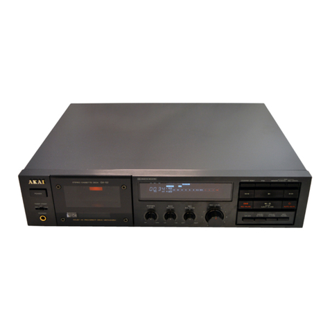
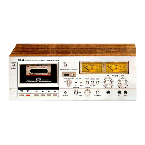
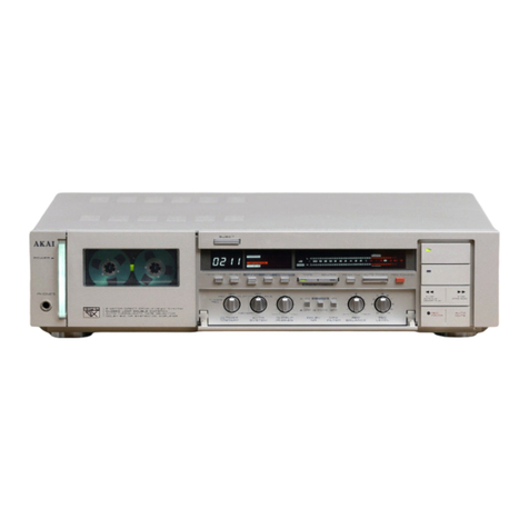
Akai GX-65 User manual

AKAI
GX-65
ma
SS
QIU
STEREO
CASSETTE
DECK
OPERATOR’S
MANUAL
To
ensure
optimum
performance
and
listening
enjoyment,
please
read
this
operator’s
manual
thoroughly.
*
Cassette
tapes
shown
in
the
illustrations
are
not
standard
acces-
sories.
ENIGUSH
..2..iceaveva
es
Page
1-
23
FrangaiS
..........65:
Page
25-
47
Doeuiseh
:sscccinceuaes
Seite
50-
71
Nederlands
...........
Pagina
74-
95
ESpanl
¢esee
eck
ae
tes
Pagina
98-119
Akai—Creative
At
Heart.

Precautions
and
table
of
contents
WARNING
Mc
a
a
Se
Power
requirements
Power
requirements
for
electrical
appliances
differ
from
area
to
area.
Please
ensure
that
your
unit
meets
the
requirements
in
your
area.
If
in
doubt,
consult
a
qualified
electrician.
220V,
50Hz
for
Europe
except
UK
240V,
50Hz
for
UK
and
Australia
110V/120V/220V/240V,
50/60Hz
convertible
for
other
countries.
Voltage
conversion
(Not
on
all
models)
Models
for
Europe,
UK
and
Australia
are
not
equipped
with
this
facility.
Each
unit
is
preset
at
the
factory
according
to
its
desti-
nation,
but
some
units
can
be
adjusted
to
110V, 120V,
220V
or
240V
as
required.
If
your
unit’s
voltage
can
be
converted:
Before
connecting
the
power
cord,
turn
the
VOLTAGE
SELECTOR
located
on
the
rear
panel
with
a
screw-
driver
until
the
correct
voltage
is
indicated.
VOLTAGE
SELECTOR
‘
402,
5
This
equipment
conform
to
No.
82/499/EEC,
87/308/
EEC
standards.
3A-En

What
you
should
know
to
protect
yourself
Never
touch
the
pl
ug
Wi
ith
wet
h
Always
pull
out
by
the
plug
and
never
the
cord.
Only
let
a
qualified
professional
repair
or
reassemble
the
stereo
cassette
deck.
An
inexperienced
person
might
touch
the
internal
parts
and
receive
a
serious
electric
shock.
e@
Never
put
anything,
especially
metal,
into
the
stereo
cas-
sette
deck.
Alawar
tar:
nds
nas
Protect
the
stereo
cassette
deck
too
@
Use
only
a
household
AC
power
source.
Never
use
a
DC
power
source.
@
{f
water
is
spilled
on
the
stereo
cassette
deck,
disconnect
it
and
call
your
dealer.
@
Make
sure
that
the
stereo
cassette
deck
is
well
ventilated
and
away
from
direct
sunlight.
@
To
avoid
damage
to
the
internal
circuits
and
the
external
surface,
keep
it
away
from
heat
(stoves,
etc.).
®
Avoid
using
spray
type
insecticide
near
the
stereo
cas-
sette
deck
as
this
could
damage
the
finish
or
cause
sud-
den
ignition
of
the
insecticide.
@
To
avoid
damaging
the
finish,
never
use
paint
thinner
or
other
similar
chemicals
to
clean
the
stereo
cassette
deck.
@
Place
the
stereo
cassette
deck
on
a
flat
and
solid
sur-
face.
e
If
you
don’t
plan
to
use
the
stereo
cassette
deck
for
a
long
period
of
time,
disconnect
the
power
cord.
Dew
formation
Dew
is
the
term
used
for
the
formation
of
moisture
on
the
very
important
tape
transport
sections
such
as
the
heads
and
the
capstan,
when
the
deck
is
used
in
places
where
hu-
midity
is
high,
or
moved
from
a
cold
place
to
a
warm
one.
If
the
deck
is
used
when
dew
is
present,
the
tape
will
stick
to
the
head
and
be
ruined,
or
it
will
not
be
transported
properly.
In
that
case,
do
not
use
the
deck
for
approximately
one
hour
until
the
deck
is
acclimatized.
Placement
If
the
cassette
deck
and
tuner
are
placed
on
top
of
each.
other,
humming
noise
may
result
during
playback.
Also
beat
noise
may
result
during
recording
of
AM
broadcasts.
In
this
case,
the
position
of
the
deck
should
be
changed.
We
re-
commend
that
the
amplifier
or
a
space
the
size
of
an
ampli-
fier
be
left
between
the
deck
and
the
tuner.
Table
of
contents
Precautions
and
table
of
Contents
............ceceeeseeceeeees
2-3
Connections
.............0:.csssceseeneeceeees
svangs
dina
dota
svubeesec
deeds
4
Before
using
your
stereo
cassette
deCK
..........:.ceeeeeeeeeees
5
GOONS
isc
tegescccseseatetitessaccecethon
cus
losagassedsceea
seve
daseweas
6-7
RRECOPGING
sive
ceakicsccaeseccned
ic
seadd
Sobea
ces
ide veg
eeeticewssapaatons
8
Tape
PlayDACK:
oi.25
05.
cc
etloes
sae
h
te
saceshdecden
es
eousbesennesdegneesi
es
9
Recording
level
adjustment
...............c.ceseeeeeeereeeet
eens
10
A
little
know-how
goes
a
long
Way
.........:ssssesceneeeeeeertes
11
Convenient
playback
features
.............cceeeecee
secs
net net
ees
12
Memory
Auto
StOP
........cceeccecceeceeceeeneeeeeseceneneeeees
12
Memory
auto
play
........cceeccecceeceeceteeeeteeseneeseeenees
12
AUtO
Play.
5
Fela
seceiesie2)
ices
cad
ceiaapisie
cdi
chee
Sela
12
Timer
controlled
recording
and
playback
.......-....-++2+0++
13
Operation
details
22.0...
cee
ceccccecsecrecteneeceecseneewers
14-19
BiaS
AGJUSTMENE
......
0.
eee
ccc
ee
cee
ee
ee
neeeseeeeneneneesentes
14
MPX
(Multiplex)
filter
.........
cece
cece
eeeerereereunerenes
15
TAPG
COUNLOR
swicicccnessedaaseceveeglevansvccsacsncenpaxescecsweeses
15
Headphone
listening
.............ccceeeeeeeeceeneveeeneneeeeneres
15
Dolby
NR
SYSteMm
00.0...
cee
eeccceecene
ee
ereeeeenercee
eee
eenees
16
Double
process
noise
reduction
system
............:0
16
Dolby
HX
PRO
Headroom
extension
system
............
17
Auto
tape
SelOCHOF
22...
cee
cecec
cc
cec
eee
teeaeceeeeeneneneusens
Peak
level
meter
...........scsceeceeeeveneeee
Tape
a
!bbing
Recording
with
microphones
Auto
StOP
MECHANISM
........cccceeceececeeeeeeeecereneeeteeners
Cassette
deck
Maintenance
...........cceceeeeesseeeeneeeeeeeeees
Troubleshooting
2.0...
cee
eeceneeeeeceeeseeeeeereseeeeeereenenerea
Specifications:
.sscc.s.ccsbetiaccsdeiek
Welewdcteecuces
sent
pacsesecaces
FOAtureS:
3
tecvesseiedcs
sucteshass
tee
cleeed
gk
tester
ea
Denson
ees
Remote
Control
2.0.0...
cccecceeceneececenee
ee
seeceenenenee
ese
eenees

Connections
Before
beginning
@
Turn
off
all
the
components
before
making
connections.
@
Connect
everything
securely.
Loose
connections
can
lead
to
malfunction.
@
To
prevent
damage
to
the
cords,
connect
and
disconnect
by
holding
the
plug,
not
the
cord.
.
@
Make
sure
that
you
connect
the
white
PIN-plugs
to
the
left
(L-white)
jacks
and
the red
PIN-plugs
to
the
right
(R-
red)
jacks.
—___———_—————
Amplifier
0900
jee
©
Cassette
deck
LINE
IN
jacks
(for
recording
signal
input)
|
ee
LINE
OUT
jacks
(for
playback
signa!
output)
_
Power
cord
and
plug
1
Connect
the
L
(Left)
and
R
(Right)
LINE
IN
jacks
of
the
cassette
deck
to
the
L
(Left)
and
R
(Right)
TAPE
REC
jacks
of
your
stereo
amplifier
with
the
provided
connec-
tion
cord.
y)
Connect
the
L
(Left)
and
R
(Right)
LINE
OUT
jacks
of
the
cassette
deck
to
the
L
(Left)
and
R
(Right)
TAPE
PLAY
jacks
of
your
stereo
amplifier
with
the
provided
connection
cord.
3
After
you
have
connected
everything
Connect
the
cassette
deck’s
power
cord
to
the
AC
OUTLET
of
your
stereo
amplifier,
optional
audio
timer
or
Ald
AD
vil
directly
to
your
housenoid
AC
outiet.
Important!
The
illustrated
power
plugs
and
cords
are
intended
for
general
reference.
The
power
plug
and
cord
used
in
your
country
may
differ
from
the
illustrations.
(Exam-
ple;
U.K.,
Australia,
U.S.A.,
Europe,
etc.)
25-En
Note
If
your
amplifier
has
2
or
more
sets
of
TAPE
jacks,
the
TAPE
1
REC
and
PLAY
jacks
are
recommended
for
connections.

Before
using
your
stereo
cassette
deck
—
How
to
load
a
cassette
tape
Press
the
POWER
button
to
turn.the
power
on.
The
FL
display
will
be
turned
on
and
the
digital
tape
counter
will
flash
on
and
off
for
a
few
seconds.
Depress
the
&
button
to
open
the
cassette
holder
and
load
a
cassette
tape.
Insert
exposed
tape
side
down.
ND
4
67
3
Push
the
middie
of
the
cassette
hoider
to
close
it.
The
tape
position
of
the
loaded
tape
will
appear
on
the
FL
display
(METAL,
CrOz
or
NORM).
Note
@
The
cassette
holder
can
be
opened
and
closed
wihtout
turning
on
the
power.
©
Do
not
press
the
&
button
when
the
cassette
deck
is
in
the
winding,
recording
or
playback
mode.
;
On
the
recording
prevention
system
and
recording
defeat
tabs
You
can
protect
your
tapes
from
accidental
recording
by
removing
the
recording
defeat
tabs
(one
for
each
tape
side)
located
above
the
A
and
B
side
indicators.
When
the
recording
defeat
tabs
are
broken,
the
recording
prevention
system
will
be
automatically
activated
to
protect
the
tape
if
the
tet
button
is
accidentally
pressed
during
play-
back.
To
record
over
the
pre-recorded
cassette
tape
again,
cover
the
holes
with
adhesive
tape.
Note
F
Do
not
cover
the
tape
position
detecting
holes
as
this
will
hinder
proper
operation
of
the
auto
tape
selector.
Remove
to
protect
Cover
with
adhesive
tape
to
re-record
Tape
position
detecting
hole
A
Word
about
cassette
tapes
Handling
@
Do
not
touch
the
tape
with
your
fingers
as
high
frequency
signals
cannot
be
recorded
in
places
which
are
not
clean.
Dirty
tapes
may
also
cause
distortion
or
sound
loss
dur-
ing
playback.
®
Do
not
leave
the
cassette
tape
near
equipment
which
generates
a
magnetic
field.
(TVs,
speaker
systems,
etc.)
Tape
slack
and
leader
tape
advancement
Tape
slack
can
cause
the
tape
to
twist
or
tangle
around
the
capstan
and
pinch
roller
and
ruin
important
recordings.
Be-
fore
using
a
cassette
tape,
take
up
tape
slack
with
a
pencil.
Most
cassette
tapes
include
clear
leader
tape
at
the
beginn-
ing.
As
recording
is
impossible
on
this
leader
tape,
it
should
be
advanced
before
recording
is
begun.
Storage
e
Always
put
the
cassette
tape
back
into
its
plastic
case
af-
ter
using
it.
Store
it
in
a
dry
place,
away
from
direct
sun-
light,
heat
(stoves,
etc.)
and
equipment
which
generates
a
magnetic
field
(TVs,
speaker
systems,
etc.).
®
Store
the.cassette
tape
with
the
tape
taken
up
at
the
fixed
speed
of
recording
or
playback.
When
the
tape
is
not
taken
up
in
an
orderly
manner
(in
other
words,
fast
for-
warded
or
rewound),
the
tape
might
stretch
or
warp.
e
If
you
are
not
going
to
use
the
cassette
tape
for
a
long
time,
rewind
or
fast
forward
the
tape
once
in
a
while.
This
is
to
prevent
music
signals
from
imprinting
themselves
over
other
music
signals
when
tape
surfaces
are
in
close
contact
for
a
long
time.
Rewinding
or
fast
forwarding
the
tape
also
prevents
moisture
condensation.
Regarding
cassette
tapes
@
We
recommend
the
use
of
cassette
tapes
specifically
made
for
recording
hi-fi
music.
@
We
do
not
recommend
the
use
of
C-120
(120
minute)
cassette
tapes.
The
tape
is
very
thin
and
can
easily
twist
or
tangle
around
the
capstan
and
pinch
roller.
®
We
do
not
recommend
the
use
of
cassette
tapes
of
poor
quality.
You
will
not
be
able
to
fully
utilize
the
capability
of
your
stereo
cassette
deck
with
this
type
of
cassette
tape.
@
We
do
not
recommend
the
use
of
ferri-chrome
cassette
tapes
for
recording.

Controls
TIMER
START
REC_OFF
PLAY
=
PHONES
On
the
FL
(Fluorescent)
display
MEMORY
Indicator
Multiplex
FILTER
Indicator
Dolby
NR
B
and
C
Indicators
NORM
(Normai),
CrOz
(Chrome)
and
METAL
Tape
Position
Indicators
TAPE
and
SOURCE
Indicators
Deck
Mode
Indicators
(REC,
<4,
>
and
PP)
INORM
CrO2
METAL
]
<<
NORM
CrO2
METAL
MEMORY
Left/Right
Channel
Peak
Level
Meter
Recording
Level
Guide
Indicators
Digital
Tape
Counter

SSETTE
DE/K
GX-65
MKIE
3X
HEAD/AUTO
TAPE
MONITOR
SYSTEM
DP
DOUBLE
CAPSTAN
REMOTE
S/NSOR
@
4
EJECT
button
To
open
the
cassette
holder
and
eject
the
cassette
tape.
@
POWER
button
To
turn
the
power
on
and
off.
©
Cassette
Lid
and
Holder
Load
a
cassette
tape
here.
@
REMOTE
SENSOR
Window
For
reception
of
the
remote
contro!
signal
from
the
RC-G65
remote
con-
trol.
Keep
away
from
strong
light
and
di-
rect
sunlight
as
this
will
interfere
with
the
remote
control
function.
©
FL
Display
Tells
you
what
the
cassette
deck
is
doing.
©
MONITOR
Button
(TAPE/SOURCE)
To
select
between
TAPE
and
SOURCE
monitor
modes.
This
button
is
incorporated
with
an
auto
monitor
system.
@
COUNTER
RESET
Button
To
reset
the
digital
tape
counter
to
the
“0000”
position.
@
COUNTER
MEMORY
Button
To
turn
the
counter
memory
system
on
and
off.
©
Operation
Buttons
(<4:Rewind
button,
®:Play
bution,
®:Fast
forward
button,
tet;
REC
PAUSE
button,
H:Stop
button,
0:AUTO
MUTE
button)
To
start
and
stop
recording
and
playback,
to
wind
the
tape
and
to
engage
the
auto
mute
mode.
@
MPX
FILTER
Switch
(=
ON/m
OFF)
To
turn
the
multiplex
filter
on
and
off.
@®
DOLBY
NR
C-TYPE/B-TYPE
Select
Switch
(=
C-TYPE/m
B-TYPE)
To
select
between
B
type
or
C
type
noise
reduction
for
recording
and
playback
purposes.
@®
DOLBY
NR
ON/OFF
switch
(=.
ON/m.
OFF)
To
turn
the
DOLBY
NR
system
on
and
off
for
recording
and
playback
purposes.
@®
REC
LEVEL
Control
To
set
the
recording
input
level.
The
level
adjustment
is
the
same
amount
for
both
left
and
right
channels.
@®
REC
BALANCE
Control
(LEFT/RIGHT)
To
set
the
recording
input
level
left
and
right
channel
balance.
Normally
set
the
control
to
the
cen-
ter
click
“
¥”
position.
®
BIAS
Control
(—20/+20)
To
adjust
the
recording
bias
current
during
recording.
The
bias
adjustment
range
is
be-
tween
—20%
and
+20%
of
the
proper
bias
current
for
Normal,
CrO2
and
Metal
position
tapes.
Normally
set
the
control
to
the
center
click
“O”
position.
@®
PHONES
LEVEL
Control
(MIN/
MAX)
To
adjust
the
output
level
of
the
PHONES
jack.
®
PHONES
Jack
For
headphone
connection.
@®
TIMER
START
Switch
(REC/OFF/
PLAY)
To
select
operation
of
the
timer
start
function
when
the
power
is
turned
on.
;

Recording
Before
beginning
@
Set
the
TIMER
START
switch
to
OFF.
©
Set
the
MPX
FILTER
switch
to.=
for
normal
recording
purposes.
@
Turn
on
the
power
of
all
the
components.
After
the
power
is
turned
on,
the
operation
buttons
cannot
be
used
for
a
few
seconds
while
the
cassette
deck
stabi-
lizes
itself.
@
Select
the
recording
source
with
the
amplifier’s
input
selector
or
the
recording
output
selector.
@
Check
the
cassette
tape
being
used
for
recording.
Make
sure
the recording
defeat
tabs
are
intact
and
that
the
tape’s
recording
time
is
of
sufficient
length.
3
HEAD
CLOSED
LOOP
DOUBLE
CAPSTAN
Operation
1
Press
the
&
button
and
load
a
cassette
tape.
Insert
exposed
tape
side
down
and
close
the
cassette
holder.
2
Set
the
DOLBY
NR
ON/OFF
and
C-TYPE/B-TYPE
se-
,
lect
switches
as
follows:
Recording
with
DOLBY
C-type
NR
ov...
eeeeceesesseeeeeeeeees
Set
the
DOLBY
NR
ON/OFF
switch
to
=
and
the
C-TYPE/B-TYPE
select
switch
to
.=.
Recording
with
DOLBY
B-type
NR............:.ccseseeeeseeeene
Set
the
DOLBY
NR
ON/OFF
switch
to
=
and
the
C-TYPE/B-TYPE
select
switch
to
.m.
Recording
without
Dolby
NR........-..:ccssessseeserrestetteneeeees
Set
the
ON/OFF
switch
to
2m.
3
Standby
for
recording
Press
the
te!
button.
The
cassette
deck
will
go
into
the
recording
standby
mode
and
the
MONITOR
switch
will
be
automatically
set
to
SOURCE.
The
REC
and
SOURCE
indicators
will
light
and
the
>
indicator
will
flash
on
and
off.
4
Recording
level
adjustment
Test
play
the
source
and
set
the
recording
level
with
the
REC
LEVEL
control.
The
standard
recording
level
should
not
exceed
the
end
of
the
recording
level
guide
on
the
peak
level
meter.
To
start
recording
Press
the
>
button.
The
&
indicator
will
stay
lit
and
the
SOURCE
indicator
will
be
replaced
by
the
TAPE
indicator.
The
cassette
deck
will
stop
automatically
when
the
end
of
the
tape
is
reached.
The
deck
mode
indicator
will
dis-
appear
and
the
TAPE
indicator
will
be
replaced
by
the
SOURCE
indicator.
To
stop
recording
Press
the
li
button.
The
cassette
deck
will
stop
immediately.
The
deck
mode
in-
dicator
will
disappear
and
the
TAPE
indicator
will
be
re-
placed
by
the
SOURCE
indicator.
To
stop
recording
temporarily
Press
the
!et
button
during
recording.
The
[>
indicator
will
flash
on
and
off
and
the
TAPE
indicator
will
be
replaced
by
the
SOURCE
indicator.
To
resume
recording
Press
the
>
button.
The
>
indicator
will
light
and
the
SOURCE
indicator
will
be
replaced
by
the
TAPE
indicator.
Note
@
Set
the
BIAS
control
to
its
center
click
“O”
position
for
nor-
mal
recording.
Refer
to
page
14
for
operation
details.
@
After
recording,
turn
off
all
the
components.

Tape
playback
Before
beginning
@
Set
the
TIMER
START
switch
to
OFF.
@
Turn
on
the
power
of
all
the
components.
After
the
power
is
turned
on,
the
operation
buttons
cannot
be
used
for
a
few
seconds
while
the
cassette
deck
sta-
bilizes
itself.
@
Set
the
amplifier’s
input
selector
to
the
TAPE
position.
CLOSED
LOOP
DOUBLE
CAPSTAN
|
Press
the
&
button
to
open
the
cassette
holder
and
load
the
cassette
tape.
Insert
exposed
tape
side
down
and
close
the
cassette
holder.
2
Set
the
DOLBY
NR
ON/OFF
and
C-TYPE/B-TYPE
se-
lect
switches
according
to
how
the
tape
was
recorded:
Tapes
recorded
with
DOLBY
C-type
NR
.........ceeeerreees
Set
the
DOLBY
NR
ON/OFF
switch
to
=
and
the
C-TYPE/B-TYPE
select
switch
to
=.
Tapes
recorded
with
DOLBY
B-type
NR..........cccseeseeee
Set
the
DOLBY
NR
ON/OFF
switch
to
=
and
the
C-TYPE/B-TYPE
seiect
switch
to
mm.
Tapes
recorded
without
Dolby
NR.........:csssssseseeeseeenees
Set
the
ON/OFF
switch
to
mm.
3
To
start
playback
Press
the
>
button.
The
>
and
TAPE
indicators
will
appear
on
the
FL
dis-
|
play
and
playback
will
begin.
The
cassette
deck
will
stop
automatically
when
the
end
of
the
tape
is
reached.
To
stop
playback
Press
the
lf
button.
The
deck
mode
indicator
will
go
off.
To
wind
the
tape
quickly
To
wind
the
tape
to
the
end
Press
the
®
button.
The
PP
indicator
will
light
up
while
the
tape
is
winding.
To
rewind
the
tape
to
the
beginning
Press
the
<#d
button.
The
<4
indicator
will
light
up
while
the
tape
is
rewinding.
After
playback
Turn
off
all
the
components.

Recording
level
adjustment
Basic
recording
level
adjustment
For
basic
recording
level
adjustment,
set
the
REC
LEVEL
contro!
so
that
the
recording
level
does
not
exceed
the
re-
cording
level
guide
indicators
on
the
peak
level
meter
when
the
cassette
deck
is in
the
source
monitor
mode
(the
SOURCE
indicator
will
be
on
the
FL
display).
The
recording
level
guide
indicators
will
vary
according
to
the
tape
position
of
the
loaded
tape.
Recording
level
balance
adjustment
Use
the
REC
BALANCE
control
as
follows:
To
decrease
the
right
channel
level:
Turn
the
REC
BALANCE
control
toward
LEFT.
To
decrease
the
left
channel!
level:
Turn
the
REC
BALANCE
control
toward
RIGHT.
*
Set
the
REC
BALANCE
control
to
the
center
click
“V”
position
for
normal
stereo
recording.
To
make
better
recordings
To
make
better
recordings,
the
recording
input
levels
must
be
correct.
The
recording
input
levels
should
be
set
as
high
as
possible,
without
exceeding
the
recommended
levels
indicated
on
the
peak
level
meter.
If
the
recording
levels
are
too
high,
distor-
tion
will
result.
if
the
input
levels
are
too
low,
noise
such
as
tape
hiss
will
become
noticeable.
Make
certain
that
the
re-
cording
input
levels
match
the
maximum
saturation
levels
of
the
music
source,
which
can
be
monitored
on
the
peak
level
meter.
Monitor
the
input
source
signals
by
pressing
the
1#!
button
before
you
begin
recording
(while
you
are
test
playing
the
music
source).
The
recording
level
will
be
displayed
on
the
peak
level
meter
and
can
be
adjusted
accordingly
with
the
REC
LEVEL
control.
Monitoring
:
Comparing
the
source
sound
with
the
just-recorded
sound
during
recording
Monitoring
the
source
sound
Press
the
MONITOR
button
during
recording.
The
TAPE
indicator
will
be
replaced
by
the
SOURCE
indica-
tor
and
the
cassette
deck
will
be
set
to
the
source
monitor
mode.
Monitoring
the
just-recorded
sound
Press
the
MONITOR
button
again.
The
SOURCE
indicator
will
be
replaced
by
the
TAPE
indica-
tor
and
the
cassette
deck
will
be
set
to
the
tape
monitor
mode.
What
is
the
auto
monitor
system?
The
independent
recording
and
playback
heads
in
combina-
tion
with
two
independent
amplifiers
(one
for
recording
and
another
for
playback)
let
you
listen
to
a
recording
as
it
is
be-
ing
made.
This
is
called
tape
monitoring.
By
switching
the
-
auto
monitor
system
during
recording,
you
can
compare
the
just-recorded
music
(TAPE
position)
with
the
source
music
(SOURCE
position).
In
this
way
you
can
make
sure
that
you
have
set
the
recording
input
levels
correctly.
The
tape
moni-
tor
system
of
this
cassette
deck
is
called
an
“Auto
Monitor
System”.
Besides
letting
you
manually
set
the
tape
monitor
system,
it
also
does
it
automatically.
When
the
cassette
deck
is
recording,
the
auto
monitor
system
is
set
automati-
cally
to
TAPE.
During
recording
standby,
it
is
automatically
set
to
SOURCE.
Under
normal
circumstances
there
is
no
need
for
you
to
set
the
MONITOR
switch
yourself.
—_—__---
Peak
level
meter
Recording
level
guide
indicators
TAPE
MONITOR
button
ter
>»
REC
LEVEL
control
REC
BALANCE
control
Recording
level
guide
indicator
Over
level
area
Normat
and’
CrO2
(Chrome)
position/Type
Il
_==-—-_
Sy
ee
Ss
SS
MONITOR
switch
TAPE
Recording
ampiities
—
Super
GX
head
for
recording
Super
GX
head
for
playback
Note
@
After
comparing
sounds,
set
the
cassette
deck
to
the
tape
monitor
mode
by
pressing
the
MONITOR
button.
@
The
MONITOR
switch
is
automatically
switched
between
the
source
and
tape
monitor
mode
when
operation
but-
tons
are
pressed
(the
>
button
for
example).
@
Set
the
tape
monitor
switch
on
your
arnplifier
to
the
tape
position
before
monitoring.
Refer
to
youramplifier’s
oper-
ator’s
manual
for
tape
monitoring
operation.
@
The
MONITOR
switch
is
automatically
set
to
the
tape
monitor
mode
when
the
cassette
deck’s
power
is
turned
on.

Alittle
know
how
goes
a
long
way
Auto
mute:
To
make
a
4
second
blank
space
during
recording
With
the
©
AUTO
MUTE
button
you
can
automatically
make
a
4
second
biank
space
between
selections
without
adjust-
ing
the
REC
LEVEL
controls.
During
recording:
Press
the
©
button
once
ait
the
place
you
wish
to
make
a
blank
space.
The
cassette
deck
will
go
into
the
mute
recording
mode.
The
REC
indicator
will
flash
on
and
off.
After
making
a
4
second
blank
space,
the
deck
wili
go
into
the
recording
standby
mode
and
the
[>
indicator
will
start
flashing.
The
TAPE
indicator
will
be
replaced
by
the
SOURCE
indicator.
To
resume
recording
Press
the
>
button.
The
cassette
deck
will
return
to
the
normal
recording
mode.
The
SOURCE
indicator
will
be
replaced
by
the
TAPE
idica-
tor.
To
make
a
blank
space
of
any
length
The
©
button
can
also
be
used
to
make
fonger
or
shorter
blank
spaces
or
to
erase
iong
portions
of
tape.
During
recording:
Press
the
9
button
twice
at
the
place
you
wish
to
make
a
blank
space.
The
cassette
deck
will
go
into
the
mute
recording
mode.
The
REC
indicator
will
flash
quickly.
To
resume
recording
Press
the
®
button.
The
cassette
deck
will
return
to
the
normal
recording
mode.
*
If
you
wish
to
go
to
the
recording
standby
mode
first
be-
fore
entering
the
normal
recording
mode,
press
the
!el
button
before
pressing
the
>
button.
Note
The
mute
recording
function
can
also
be
used
from
the
stop
mode
(to
erase
the
beginning
of
a
tape
or
for
bulk
erasing
for
example)
by
first
pressing
the
1¢t
button.
After
this,
press
the
©
button
once
or
twice
depending
on
how
long
you
wish
mute
recording
to
continue.
Stop
mute
recording
by
press-
ing
the
i
button.
MEMORY
RESET
—-_——--—-——
COUNTER
REC
PAUSE
To
start
recording
immediately
Simultaneously
press
the
tel
button
and
the
>
button.
The
REC
and
(>
indicators
will
light
and
the
cassette
deck
will
immediately
go
into
the
recording
mode.
To
go
from
playback
to
recording
without
stopping
the
tape
Simultaneously
press
the
button
and
the
ii
button
during
playback.
The
REC
indicator
will
light
and
the
cassette
deck
will
go
directly
into
the
recording
mode.

Convenient
playback
features
Memory
stop
and
memory
playback
operation
Memory
auio
siop
:
Winding
and
stopping
the
tape
at
the
“0000”
position
of
the
tape
counter
automatically
1
Press
the
MEMORY
button.
The
MEMORY
indicator
will
light.
During
playback,
press
the
RESET
button
at
the
point
you
wish
auto
stop
to
be
memorized.
The
tape
counter
will
be
reset
to
“OOOO”.
Press
the
<4
button
during
playback
when
you
wish
to
return
to
the
memorized
point.
©
PD
When
the
“0000”
position
of
the
digital
tape
counter
is
reached,
the
tape
will
be
stopped
automatically.
If
you
wish
to
playback
the
tape
from
that
point
again,
press
the
®
button.
To
cancel
the
memory
system
Press
the
MEMORY
button.
The
MEMORY
indicator
will
go
off.
Memory
auto
play
:
Automatic
rewind
and
playback
from
the
“0000”
point
on
the
tape
counter
1
Press
the
MEMORY
button.
The
MEMORY
indicator
will
light.
2
During
playback,
press
the
RESET
button
at
the
point
you
wish
auto
play
to
be
memorized.
The
tape
counter
will
be
reset
to
“O000”.
3
Press
the
«#4
button
and
®
button
simultaneously
when
you
wish
to
return
to
the
memorized
point.
The
memory
auto
play
system
will
be
engaged.
The
<4
indicator
will
light
and
the
[>
indicator
will
flash
on
and
'
off
while
the
tape
is
being
wound.
When
the
tape
reaches
the
“0000”
point
on
the
tape
counter,
the
cassette
deck
will
start
playback
again
au-
tomatically
womatiCany,
Note
@
The
counter
is
not
completely
accurate.
The
tape
will
stop
at
approximately
the
“O000”
position.
:
@
The
auto
stop
system
can
also
be
engaged
from
the
fast
forward
mode.
Auto
play
:
Automatic
playback
from
the
beginning
of
a
tape
Press
the
MEMORY
button
to
cancel
the
memory
sys-
tem.
The
MEMORY
indicator
will
go
off.
Press
the
<#
and
&
buttons
simultaneously.
The
<4
indicator
will
light
and
the
[>
indicator
will
flash
on
and
off
when
auto
play
is
engaged.
The
tape
will
be
rewound
to
the
beginning,
and
play-
back
will
begin
automatically.
MEMORY
indicator
MEMORY
indicator
@
The
memory
auto
play
system
will
be
engaged
from
the
rewind
mode
only.
It
cannot
be
used
from
the
fast
forward
mode.
MEMORY
indicator

Timer
controlled
recording
and
playback
This
cassette
deck
has
a
built-in
timer
start
function.
When
used
in
combination
with
an
optional
audio
timer,
recording
or
playback
can
be
started
automatically
at
any
programmed
Timer
controlled
recording
After
preparing
for
recording,
set
the
timer
to
the
timer
oper-
ation
mode.
The
connected
audio
components
will
be
turned
off
automatically.
;
Set
the
cassette
deck’s
TIMER
START
switch
to
REC.
a
TIMER
START
REC
OFF
PLAY
time.
Refer
to
the
audio
timer’s
operator’s
manual
for
opera-
tion
details.
Timer
controlled
playback
After
preparing
for
playback,
set
the
timer
to
the
timer
oper-
ation
mode.
The
connected
audio
components
will
be
turned
off
automatically.
Set
the
cassette
deck’s
TIMER
START
switch
to
PLAY.
TIMER
START
REC
OFF
PLAY
CTT)
ee
After
timer
controiied
recording
or
playback
is
finished
Set
the
TIMER
START
switch
to
OFF
before
turning
on
the
power
of
the
cassette
deck.
Note
@
Timer
start
recording
or
playback
will
begin
4
seconds
af-
ter
the
power
has
been
turned
on.
@
Once
the
timer
start
function
has
begun
the
operation
buttons
can
be
used
freely
for
normal
recording
or
play-
back
operation.
Timer
controlled
recording
@
Make
sure
your
tape
is
of
sufficient
length
for
your
re-
cording
needs.
©
Do
not
forget
to
tune
in
the
station
you
wish
to
record
with
the
connected
tuner,
and
to
set
the
amplifier
for
broad-
cast
station
recording.
@
Normally,
keep
the
VOLUME
control
set
to
the
minimum
position
during
timer
controlled
recording.
If
you
wish
to
listen
while
recording,
set
the
VOLUME
control
to
the
nor-
mal
listening
level.
Important!
The
illustrated
power
plugs
and
cords
are
intended
for
general
reference.
The
power
cord
and
plug
used
in
your
country
may
differ
from
the
illustrations.
(Exam-
ple;
U.K.,
Australia,
U.S.A.,
Europe,
etc.)
25-En
Example
connection
of
the
power
cord
Tuner
S.
=i
Household
AC
outlet
*
If
your
amplifier
is
not
equipped
with
AC
outlets,
_
connect
the
power
cords
to
the
timer’s
AC
outlet.

Operation
details
—
Bias
adjustment
Cassette
tapes
can
be
separated
widely
into
3
types:
Normal
position,
Chrome
(CrOz)
position
and
Metal
position.
Recording
characteristics
vary
slightly,
even
with
tapes
that
have
the
same
position.
For
good
recording
results,
precise
adjustment
of
the
tape’s
bias
is
necessary.
This
cassette
deck
is
equipped
with
a
BIAS
control
which
is
ca-
pable
of
adjusting
the
recording
bias
current
from
a
range
of
-20
%to
+20
%
of
the
proper
bias
current
for
each
tape
position.
—
CLOSED
LOOP
DOUBLE
CAPSTAN
Operation
For
bias
adjustment,
FM
inter-sation
noise
is
used
as
a
test
signal.
4
Set
your
tuner
to
a
point
between
FM
stations.
5
Record
the
FM
inter-station
noise
at
a
level
of
approxi-
mately
—20dB.
.
During
recording,
repeatedly
press
the
MONITOR
but-
ton
to
switch
between
the
source
sound
and
the
re-
corded
sound.
|
If
the
recorded
sound
has
a
pronounced
higher
hiss
in
comparison
to
the
source
sound,
recording
bias
is
set
too
low.
If
the
recorded
sound
has
a
lower
hiss
in
comparison
to
the
sound
source,
recording
bias
is
set
too
high.
If
both
the
recorded
and
source
sound
are
the
same,
the
recording
bias
is
set
to
the
proper
level
4
Adjust
the
BIAS
control
as
follows:
To
increase
recording
bias
................
ee
ceeeeseeeeeeeeesenentees
Turn
the
control
toward
+.
To
decrease
recording
bias.........
sedacadeysanaubessiveesdsceceeeses
Turn
the
control
toward
—.
Record
the
inter-station
noise
again
and
use
the
MONI-
TOR
button
to
re-check
the
sound
difference.
After
recording
bias
adjustment
is
completed
Set
the
cassette
deck
to
the
normal
recording
mode.
Note
7
e
Avoid
setting
the
BIAS
control
to
the
maximum
+
or
—
positions,
since
the
frequency
characteristics
of
the
tape
will
change
sharply.
@
Normally
set
the
BIAS
control
to
“0”
when
using
one
of
the
standard
reference
tapes
listed
(Refer
to
page
18).
@
Do
not
turn
the
BIAS
control
during
normal
recording
or
once
bias
adjustment
has
been
completed.
@
The
BIAS
control
is
not
effective
during
playback.

MPX
(Multiplex)
filter
Set
the
MPX
FILTER
switch
to
=.
When
high
frequency
rel
signa
stereo
recording,
use
of
a
noise
reduction
system
alone
is
not
enough.
In
this
case,
it
is
necessary
to
use
the
MPX
fil-
ter.
What
is
the
MPX
filter?
FM
stereo
signals
contain
19kHz
pilot
signals
and
38kHz
subcarrier
signals
which
convey
the
left
and
right
channel
in-
formation.
These
signals
are
necessary,
but
they
must
be
removed
form
the
output
signals
of
the
tuner.
If
these
signals
are
not
removed,
they
can
affect
the
DOLBY
NR
system.
The
MPx
filter
is
designed
to
remove
these
pilot
tone
signals
from
the
recording.
When
to
use
the
MPX
FILTER
switch
Use
this
switch
only
when
recording
with
the
DOLBY
NR
system.
Most
high
quality
tuners
have
filters
to
suppress
FM
pilot
tone
signals.
With
these
tuners,
you
can
leave
the
MPX
FILTER
switch
OFF.
With
other
tuners,
the
MPX
FILTER
switch
should
be
turned
ON.
The
MPX
FILTER
switch
should
also
be
turned
on
when
you
have
monitored
the
just
recorded
music
and
feel
that
the
sound
quality
is
not
right.
s
signals
are
de-emphasized
during
FM
a
fASiZou
Gu
@
50180
i=
0)
Tape
counter
The
digital
tape
counter
shows
the
amount
of
tape
that
has
been
played
back
or
recorded.
Press
the
RESET
button
to
reset
the
counter
to
“0000”.
Note
;
@
The
tape
counter
is
intended
as
a
guide
only
and
is
not
an
exact
measurement
of
real
time.
@
The
tape
counter
will
be
reset
to
“O000”
when
the
power
is
turned
off
or
if
the
RESET
button
is
pressed.
Headphone
listening
1
Connect
a
pair
of
headphones
to
the
PHONES
jack.
y
Adjust
the
playback
level
with
the
PHONES
LEVEL
con-
trol.
Caution
Listening
at
high
volume
levels
for
long
periods
of
time
may
damage
your
hearing.
;
Digital
tape
counter
PHONES
jack

Dolby
NR
system
Set
the
proper
Dolby
Noise
Reduction
sys-
tem
before
ali
recording
and
playback
Op-
erations
When
playing
back
a
tape,
set
the
noise
reduction
selector
switch
to
the
setting
that
was
used
when
the
tape
was
re-
corded.
Set
the
noise
reduction
selector
switch
to
OFF
for
tapes
that
were
recorded
without
the
use
of
the
Dolby
NR
system.
What
is
the
Dolby
Noise
Reduction
(NR)
System?
The
DOLBY
NR
system
is
a
noise
reduction
system
de-
signed
to
reduce
tape
noise
caused
when
high
frequency
soft
sounds
are
recorded.
The
DOLBY
NR
system
does
this
by
lowering
the
noise
floor
in
order
to
increase
the
dynamic
room
in
the
high
frequency
range
above
5kHz.
During
recording,
the
DOLBY
NR
encoder
circuit
boosts
soft
high
frequency
sounds,
and
then
during
playback
the
DOLBY
NR
decoder
circuit
lowers
what
was
boosted
by
ex-
actly
the
same
amount
to
restore
the
high
frequencies
to
their
original
levels.
At
the
same
time,
tape
noise
is
lowered
.
by
the
same
amount.
The
result
is
reduction
of
up
to
10dB
in
unwanted
tape
noise
in
the
high
frequencies.
:
What
is
the
difference
between
Dolby
B-type
and
C-type
NR
systems?
B-type
:
This
is
the
conventional
Délby
NR
system.
It
boosts
or
lowers
the
low-level
signals
at
high
frequencies
‘only
(more
than
5kHz)
and
reduces
tape
noise
by
10dB.
Compared
to
Dolby
B
NR,
it
operates
at
lower
fre-
quencies
(from
500HZz)
for
uniform
noise
reduction
across
more
of
the
audible
spectrum.
Tape
noise
is
reduced
by
as
much
as
20GB.
C-type
:
Double
process
noise
reduction
system
In
a
conventional
noise
reduction
system,
one
circuit
acts
both
as
an
encoder
and
decoder,
and
is
switched
to
one
or
the
other
accordingly.
The
double
process
noise
reduction
system
has
an
encoder
circuit
in
the
recording
amplifier
section,
and
a
decoder
in
the
playback
amplifier
section.
The
double
process
noise
re-
duction
system
is
used
in
cassette
decks
with
3
independent
heads
(recording,
playback,
and
erase).
Therefore,
when
re-
cording
with
a
noise
reduction
system,
you
can
immediately
confirm
the
effect
of
the
noise
reduction
by
monitoring
the
just
recorded
music.
A
rding
Source
Result
Loud
Encoded
tape
|
Loud
|
Encoder
eg
sounds
|>
og
4
(<=)
Soft
sounds
ie
soft
sounds
i
Playback
Tape
Result
.
bier
NR
system
Encoded
tape
Ear
Boosted
soft
sounds
Decoder
>
00
9
Loud
sounds
Restored
soft
sounds
Tape
noise
Lowered
tape
noise

DOLBY
HX
PRO
Headroom
extension
system
The
Dathy
Ly
DOP
at.
The
Dolby
HX
PRO
system
(HX
stands
for
Headroom
eX-
tension)
is
a
system
designed
to
improve
the
saturation
level
of
cassette
tapes
by
controlling
the
bias
current.
This
im-
proved
saturation
level
means
clearer
sound
when
recording
classical
music,
or
other
music
that
contains
many
instru-
ments.
Although
it
is
a
Dolby
system
the
HX
PRO
headroom
extension
system
should
not
be
confused
with
Dolby
NR
as
it
is
not
a
noise
reduction
system.
The
Dolby
HX
PRO
headroom
extension
system
is
basically
a
circuit
used
in
cassette
decks
that
makes
use
of
the
fact
that
the
amount
of
high
frequency
energy
that
the
tape
can
hold
varies
according
to
the
amount
of
bias
current
present.
Less
bias
current
will
result
in
more
headroom
for
the
high
frequencies,
but
at
an
increase
in
low-frequency
distortion.
More
bias
helps
to
lower
distortion,
but
results
in
loss
of
high
frequency
“headroom”.
During
recording,
the
Dolby
HX
PRO
headroom
extension
circuit
monitors
the
recording
signal.
When
high
frequency
peaks
that
are
too
high
are
detected,
the
bias
is
reduced
momentarily
so
that
those
peaks
can
be
accomodated.
This
is
especially
helpful
for
signals
which
have
high
levels
at
high
frequencies.
When
these
peaks
are
no
longer
present,
the
bias
is
restored
to
the
normal
level.
Even
when
using
a
normal
position
tape
during
recording,
the
Dolby
HX
PRO
headroom
extension
system
works
to
im-
prove
its
saturation
level
to
almost
that
of
a
metal
position
tape.
Because
the
system
is
built
into
the
recording
circuits,
it
is
working
whenever
recording
is
taking
place.
Cassette
tapes
recorded
with
the
Dolby
HX
PRO
headroom
extension
system
can
be
played
back
without
any
problems
on
any
cassette
deck.
Block
diagram
of
the
DOLBY
HX
PRO
headroom
extension
system
input
O
Signal
Re
rr
errr
ne
a
re
Control
signal
Bias
+
Signal
Bias
+
Signal
*
Dolby
noise
reduction
and
HX
Pro
headroom
extension
manufactured
under
license
from
Dolby
Laboratories
Li-
censing
Corporation.
HX
Pro
originated.by
Bang
&
Olufsen.
z
VCA:
Voltage
Controlled
Amplifier
“DOLBY”,
the
double-D
symbol
OO
and
“HX
PRO”
are
trademarks
of
Dolby
Laboratories
Licensing
Corporation.

Auto
tape
selector
How
the
tape
positions
are
detected
Cassette
tapes
can
be
separated
widely
into
three
types:
Normal
position,
chrome
(CrOz)
position
and
metal
position.
Because
tape
performances
differ
according
to
tape
posi-
tion,
to
fully
utilize
the
performance
of
each
tape
the
cas-
sette
deck’s
recording/playback
characteristics
such
as
bias
and
equalization
must
be
set
to
suit
each
tape
position.
This
cassette
deck
is
equipped
with
an
auto
tape
selector
which
functions
automatically
after
you
have
loaded
a
cas-
sette
tape.
Once
loaded,
the
metal,
CrOz
or
normal
tape
po-
sition
is
indicated
on
the
FL
display.
How
the
Auto
Tape
Selector
operates
When
a
cassette
tape
is
loaded,
the
cassette
deck
detects
the
‘tape
position
by
sensing
the
tape
position
notches
lo-
cated
on
top
of
the
cassette
case,
as
illustrated.
Note
@
Do
not
use
a
cassette
tape
which
does
not
have
notches
for
triggering
the
tape
position,
as
this
will
result
in
re-
cordings
of
poor
quality.
@
We
do
not
recommend
the
use
of
ferri-chrome
cassette
tapes
for
recording.
Standard
reference
tapes
of
the
cassette
deck
Tape
position
Reference
tape
CrOQ2
(Chrome)
TDK
SA/C-60
|
*
©-60
(60
minutes)
tapes
are
the
standard
reference
tapes.
:
Peak
level
meter
The
peak
level
meter
shows
the
peak
(maximum)
level
of
re-
cording
and
playback
signals.
By
monitoring
the
peak
level,
it
is
possible
to
set
the
recording
controls
of
this
deck
to
realistically
reproduce
the
dynamic
characteristics
of
the
original
source.
The
standard
recording
level
of
this
meter
is
indicated
at
OcB
at
a
level
of
250
nWb/m.
The
peak
level
meter
con-
forms
to
IEC
standards.
Recording
defeat
tab
CrOz
position
Metal
position
Tape
position
indicators
Peak
level
meter
eS
~~
See
eae

Tape
Dubbing
:
Making
a
copy
from
an
original
tape
For
tape
dubbing,
normally
connect
both
cassette
decks
to
the
amplifier.
Refer
to
the
amplifier's
operator’s
manual
for
operation
details.
it
is
also
possible
to
connect
directly,
deck
to
deck.
Set
the
recording
controls
(noise
reduction,
recording
level,
etc.)
ex-
actly
as
you
would
for
standard
recording.
Recording
with
microphones
To
record
from
microphones
it
will
be
necessary
to
connect
a
microphone
mixer
(not
included)
to
the
LINE
IN
jacks
of
the
cassette
deck.
The
microphones
can
then
be
connected
to
the
microphone
mixer.
Connections
Cassette
deck
for
playback
Cassette
deck
for
recording
To
output
jacks
of
a
microphone
mixer
Auto
stop
mechanism
This
cassette
deck
is
equipped
with
an
auto
stop
mechan-
ism
that
automatically
stops
the
tape
when
it
has
been
fully
fast
forwarded,
fast
rewound
or
at
the
end
of
playback
or
re-
cording.

Cassette
deck
maintenance
Keep
your
stereo
cassette
deck
clean
After
prolonged
use,
parts
of
your
cassette
deck
which
come
into
contact
with
the
tape
(Heads,
capstans,
pinch
rollers
and
tape
guides,
etc.)
become
dirty
due
to
oxide
from
the
tape
and
other
contaminants.
This
can
fead
to
such
problems
as
no
sound,
distorted
sound
due
to
unstable
tape
transport,
etc.
To
ensure
good
performance,
you
should
periodically
clean
your
stereo
cassette
deck.
How
to
remove
the
cassette
lid
1
Press
the
&
button
to
open
the
cassette
holder.
-)
Grasp
both
sides
of
the
cassette
lid
and
gently
pull
up
to
remove.
Align
the
cassette
lid
with
the
cassette
holder
and
push
it
down
in
the
opposite
direction
of
the
arrows
to
replace
the
cassette
lid.
Cassette
lid
Mechanism
layout
Super
GX
head
for
Recording
Super
GX
head
for
Playback
Capstan
(for
tape
supply)
Capstan
(for
tape
take-up)
—!|
Erase
head
Pinch
roller
Tape
guide
Pinch
roller
Cleaning
the
deck
ae
Use
the
optional
accessory
Akai
Cleaning
kit
CK-310
or
cleaning
tape.
Dip
the
cotton
swab
into
the
appropriate
cleaning
fluid
(most
cleaning
kits
contain
two
types
of
cleaning
fluid;
one
for
me-
tal
parts
and
one
for
rubber
and
plastic
parts)
and
wipe
the
surface
of
the
heads,
tape
guides,
capstans
and
pinch
roll-
ers.
After
cleaning,
wipe
with
a
dry
cotton
swab.
Use
your
stereo
cassette
deck
only
after
the
parts
have
completely
dried.
*
Use
a
liquid
cleaner
exclusively
meant
for
t
best
results,
always
clean
your
stereo
cassett
fore
an
important
recording.
Keeping
the
head
demagnetized
£
S
After
much
use,
slight
magnetism
can
build-up
on
the
re-
cording
and
playback
head
causing
loss
in
high
frequency
sound
and
increases
in
noise.
To
eliminate
this
problem
you
should
periodically
demagnetize
the
head
with
the
optional
accessory
Head
Demagnetizer
AH-15.
Damagnetize
the
metal
parts
of
the
capstan
as
well.
Before
demagnetizing
Turn
off
your
stereo
cassette
deck.
Keep
the
cabinet
clean
too
@
Clean
the
cabinet
with
a
soft,
dry
cloth.
@
If
the
cabinet
is
excessively
dirty,
clean
it
with
a
mild
de-
tergent.
@
Never
use
paint
thinner,
etc.
to
clean
the
cabinet,
as
this
may
damage
the
finish.
Other manuals for GX-65
1
Table of contents
Languages:
Other Akai Cassette Player manuals