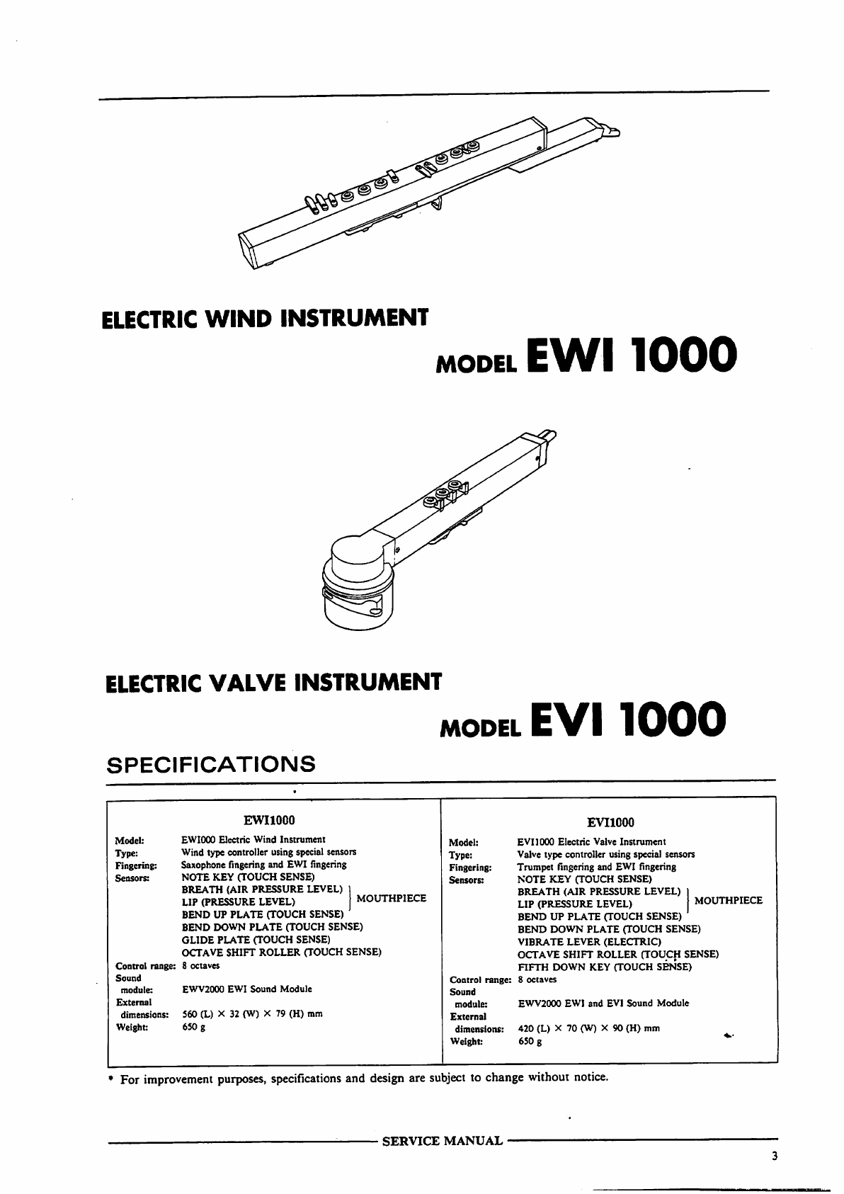
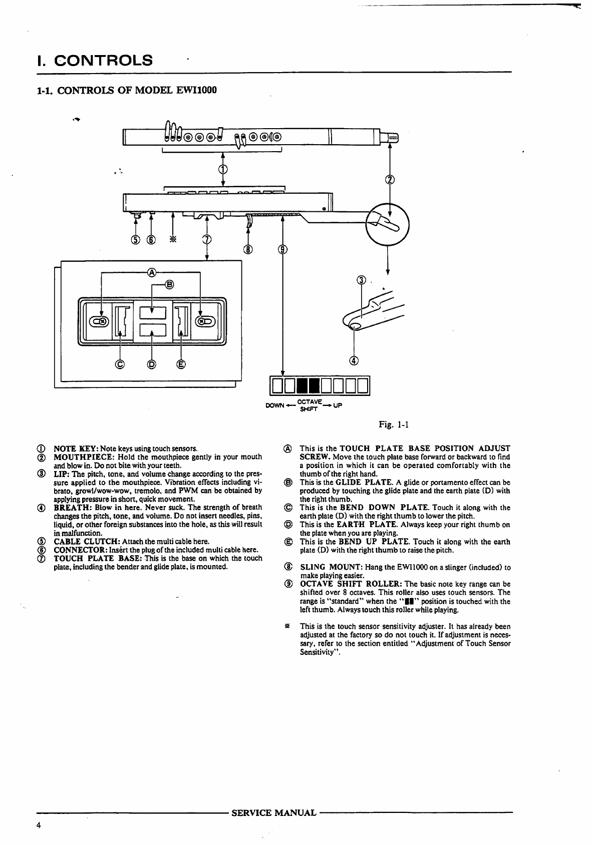
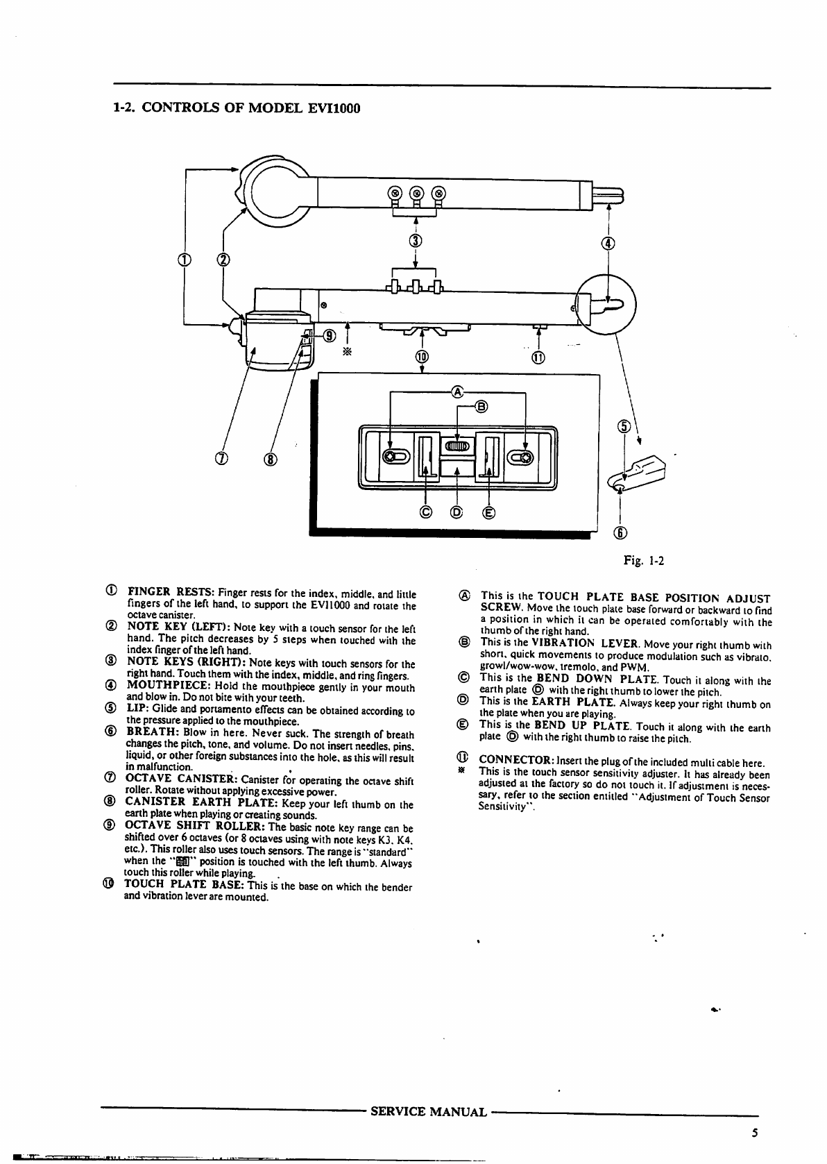
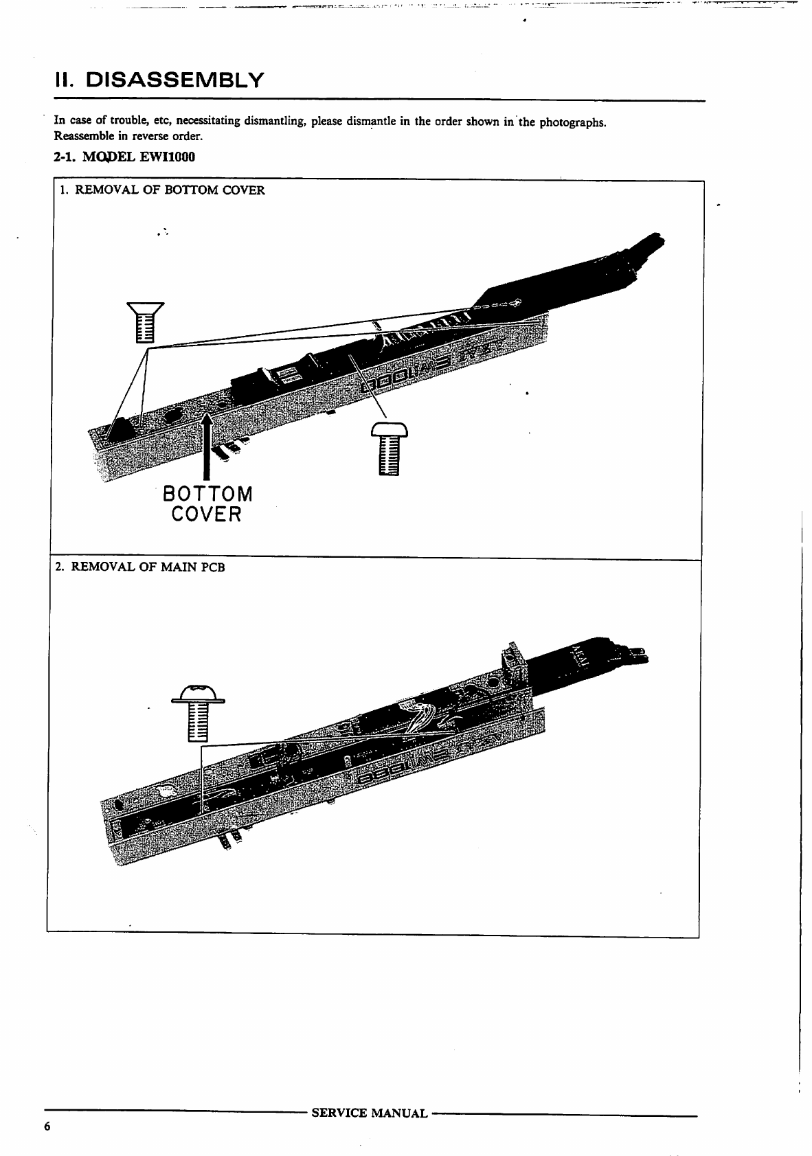
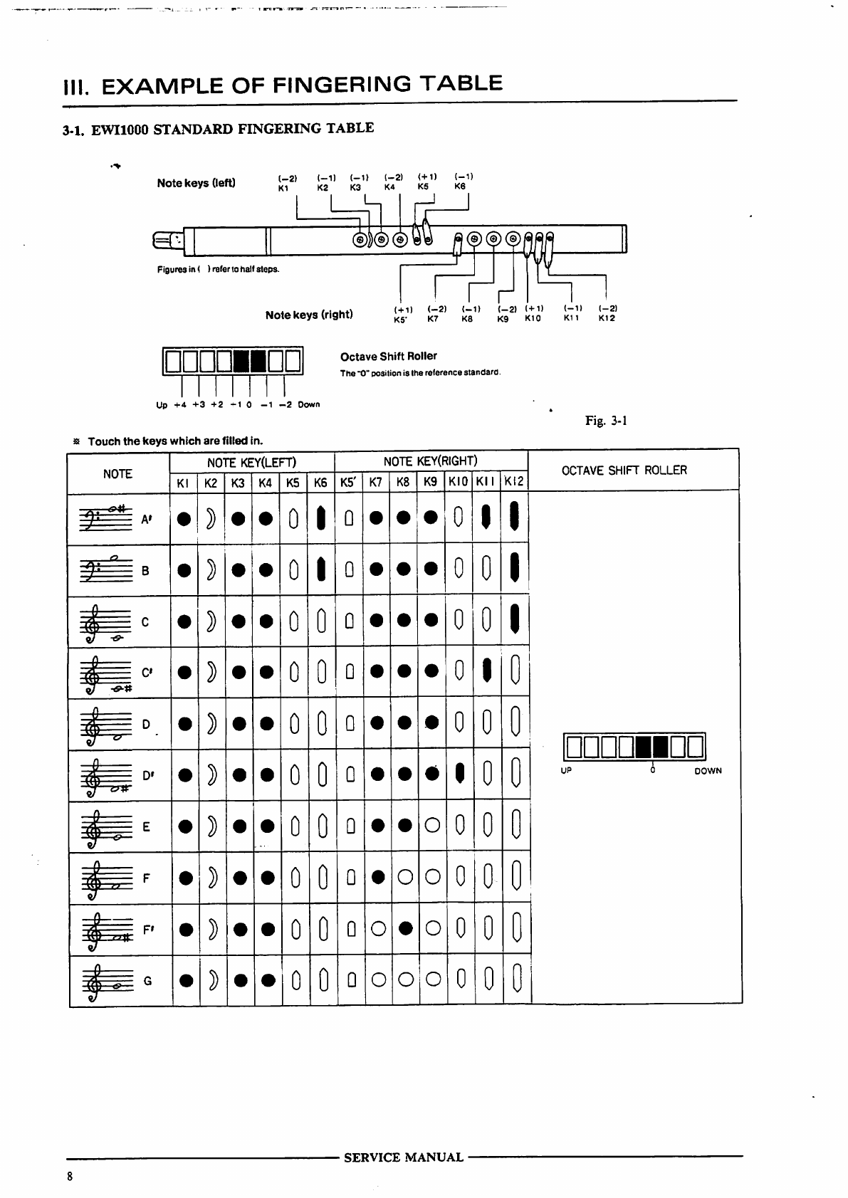
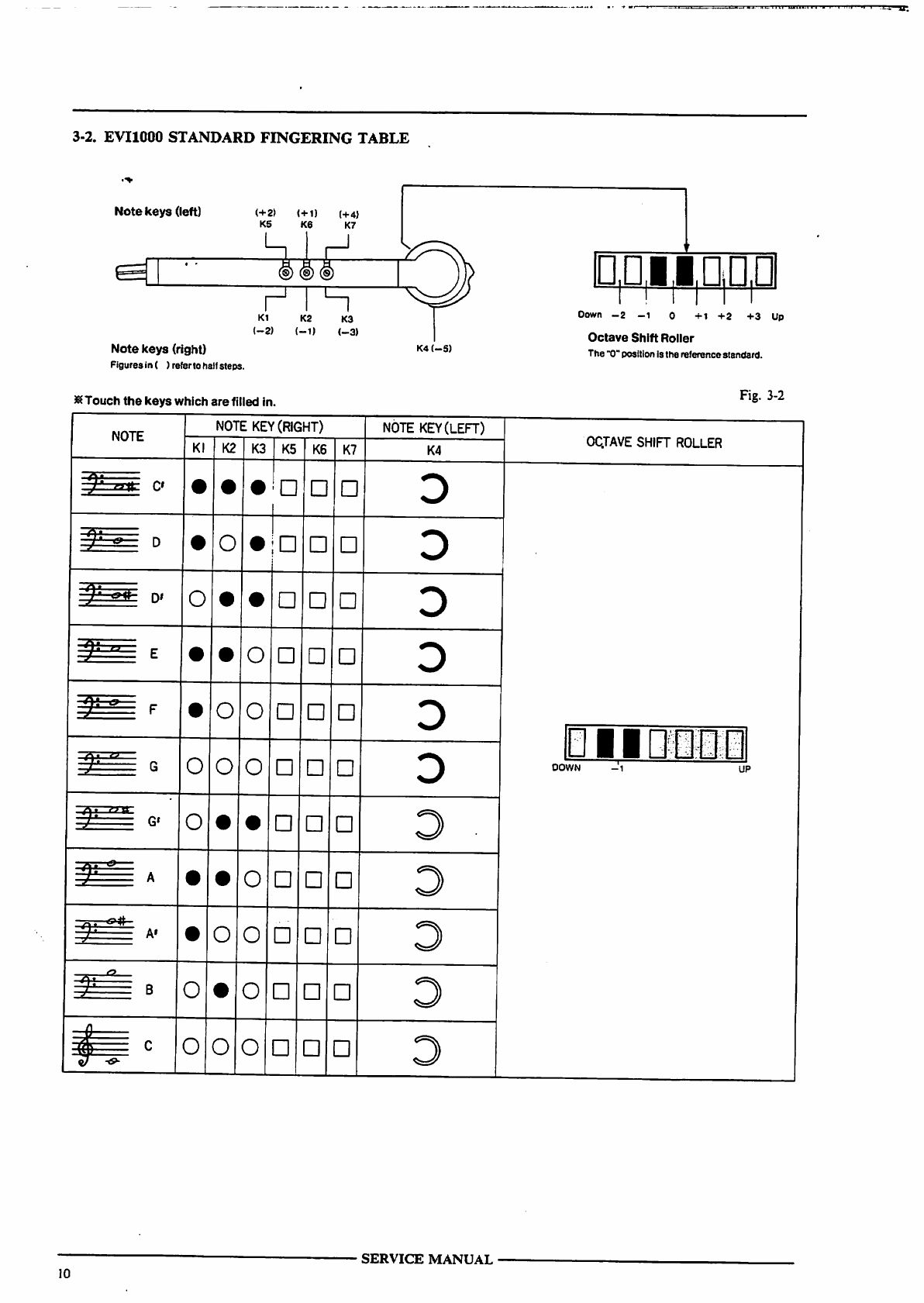
Akai EWI 1000 User manual

AK
AI
seruice
rnnmiM
MODEL
EWI
1000
MODEL
EVI
1000
!.DD
°DDDD
°D
gggg
6
ddddQdQ
MODEL
EWV
2000
ELECTRIC
WIND
INSTRUMENT
MODEL
EWI
1
•
IIII
ELECTRIC
VALVE
INSTRUMENT
MODEL
EVM
IIIII
EWI
&
EVI
SOUND
MODULE
MODEL
EWV
2
•
•
II
CAUTION:
Before
servicing,
save
all
data
to
cassette
tape
to
protect
customer's
program-
.
ming
data
from
being
damaged.
Scan by Manual Manor
http://www.markglinsky.com/ManualManor.html

*
SAFETY
INSTRUCTIONS
PRECAUTIONS
DURING
SERVICING
1.
Parts
identified
by
the
A
symbol
are
critical
for
safety.
,^
Replace
only
with
parts
number
specified.
2.
In
addition
to
safety,
other
parts
and
assemblies
are
specified
for
conformance
with
such
regulations
as
those
applying
to
spurious
radiation.
These
must
also
be
replaced
only
with
specified
replacements.
Examples:
RF
converters,
tuner
units,
antenna
selector
switches,
RF
cables,
noise
blocking
capacitors,
noise
blocking
filters,
etc.
3.
Use
specified
internal
wiring.
Note
especially:
1)
Wires
covered
with
PVC
tubing
2)
Double
insulated
wires
3)
High
voltage
leads
4.
Use
specified
insulating
materials
for
hazardous
live
parts.
Note
especially:
1)
Insulation
Tape
2)
PVC
tubing
3)
Spacers
(Insulating
Barriers)
4)
Insulation
sheets
for
transistors
5)
Plastic
screws
for
fixing
microswitch
(especially
in
turntable)
5.
When
replacing
AC
primary
side
components
(transform
ers,
power
cords,
noise
blocking
capacitors,
etc.),
wrap
ends
of
wires
securely
about
the
terminals
before
soldering.
6.
Observe
that
wires
do
not
contact
heat
producing
parts
(heatsinks,
oxide metal
film
resistors,
fusible
resistors,
etc.).
•
INFORMATION
7.
Check
that
replaced
wires
do
not
contact
sharp
edged
or
pointed
parts.
8.
Also
check
areas
surrounding
repaired
locations.
9.
Use
care
that
foreign
objects
(screws,
solder
droplets,
etc.)
do
not
remain
inside
the
set.
SAFETY
CHECK
AFTER
SERVICING
Confirm
the
specified
insulation
resistance
between
power
cord
plug
prongs
and
externally
exposed
parts
of
the
set
is
greater
than
10
M
ohms,
but
for
equipment
with
external
antenna
terminals
(tuner,
receiver,
etc.)
and
is
intended
for
[C]
or
[X]
,
specified
insulation
resistance
should
be
head
phone
jacks,
line-in-out
jacks,
etc.
more
than
2.2
M
ohms
(ground
terminals,
microphone
jacks).
PRECAUTIONS
FOR
LITHIUM
BATTERY
The
lithium battery
may
explode
when
heated
excessively.
[OBSERVE
THE FOLLOWING
WHEN
REPLACING]
•
replace
with
the
same
make
and
type
only.
•
Use
soldering
iron
in
"recommended
way"
only.
•
Place
battery
in
correct
polarity.
•
Do
not
short
the
terminals.
•
Do
not
recharge
battery.
•
Do
not
dispose
of
battery
in
fire.
[DANGER]
[RECOMMENDED
WAY]
SYMBOLS
FOR
PRIMARY
DESTINATION
Alphabet
indicates
the
destination
of
the
units
as
listed
below.
Symbols
lh
Principal
Destinations
USA
UK
Canada
Europe
(except
UK)
Japan
Australia
W.
Germany
only
Universal
Area
Custom
version
VOLTAGE
CONVERSION
(IE,
V.
B,
Si
Model
only)
Before
connecting
the
power
cord,
SET
the
VOLTAGE
SELECTOR
located
on
the
bottom
plate
with
a
screwdriver
so
that
the correct
voltage
is
indicated.
VOLTAGE
SELECTOR
SERVICE
MANUAL
Scan by Manual Manor
http://www.markglinsky.com/ManualManor.html

ELECTRIC
WIND
INSTRUMENT
MODEL
EWI
1
ELECTRIC
VALVE
INSTRUMENT
MODEL
EVI1
•
Hit
SPECIFICATIONS
For
improvement
purposes,
specifications
and
design
are
subject
to
change
without
notice.
SERVICE
MANUAL
Scan by Manual Manor
http://www.markglinsky.com/ManualManor.html

I.
CONTROLS
1-1.
CONTROLS
OF
MODEL
EWI1000
DOWN—
<*™*-*UP
Fig.
1-1
(D
NOTE
KEY:
Note
keys
using
touch
sensors.
(2)
MOUTHPIECE:
Hold
the
mouthpiece
gently
in
your
mouth
and
blow
in.
Do
not
bite
with
your
teeth.
(D
LIP:
The
pitch,
tone,
and
volume
change
according
to
the
pres
sure
applied
to
the
mouthpiece.
Vibration
effects
including
vi
brato,
growl/wow-wow,
tremolo,
and
PWM
can
be
obtained
by
applying
pressure
in
short,
quick
movement.
(4)
BREATH:
Blow
in
here.
Never
suck.
The
strength
of
breath
changes
the
pitch,
tone,
and
volume.
Do
not
insert
needles,
pins,
liquid,
or
other
foreign
substances
into
the
hole,
as
this
will
result
in
malfunction.
(D
CABLE
CLUTCH:
Attach
the
multi cable
here.
<D
CONNECTOR:
Insert
the
plug
of
the
included
multi
cable
here.
®
TOUCH
PLATE
BASE:
This
is
the
base
on
which
the
touch
plate,
including the
bender
and
glide
plate,
is
mounted.
®
This
is
the
TOUCH
PLATE
BASE
POSITION
ADJUST
SCREW.
Move
the
touch
plate
base
forward
or
backward
to
find
a
position
in
which
it
can
be
operated
comfortably
with
the
thumb
of
the
right
hand.
(§)
This
is
the
GLIDE
PLATE.
A
glide
or
portamento
effect
can
be
produced
by
touching
the
glide
plate
and
the
earth
plate
(D)
with
the
right
thumb.
©
This
is
the
BEND
DOWN
PLATE.
Touch
it
along
with
the
earth
plate
(D)
with
the
right
thumb
to
lower
the
pitch.
©
This
is
the
EARTH
PLATE.
Always
keep
your
right
thumb
on
the
plate
when
you
are
playing.
(|)
This
is
the
BEND
UP
PLATE.
Touch
it
along
with
the
earth
plate
(D)
with
the
right
thumb
to
raise
the
pitch.
®
SLING
MOUNT:
Hang
the
EWI1000
on
a
slinger
(included)
to
make
playing
easier.
CD
OCTAVE
SHIFT
ROLLER:
The
basic
note
key
range
can
be
shifted
over
8
octaves.
This
roller
also
uses
touch
sensors.
The
range
is
"standard"
when
the
"II"
position
is
touched
with
the
left
thumb. Always
touch
this
roller
while
playing.
8
This
is
the
touch
sensor
sensitivity
adjuster.
It
has
already
been
adjusted
at
the
factory
so
do
not
touch
it.
If
adjustment
is
neces
sary,
refer
to
the
section
entitled
"Adjustment
of
Touch
Sensor
Sensitivity'1.
SERVICE
MANUAL
Scan by Manual Manor
http://www.markglinsky.com/ManualManor.html

1-2.
CONTROLS
OF
MODEL
EVI1000
©
©
®
FINGER
RESTS:
Finger
rests
for
the
index,
middle,
and
little
fingers
of
the
left
hand,
to
support
the
EV11000
and
rotate
the
octave
canister.
NOTE
KEY
(LEFT):
Note
key
with
a
touch
sensor
for
the
left
hand.
The
pitch
decreases
by
5
steps
when
touched
with
the
index
finger
of
the
left
hand.
NOTE
KEYS
(RIGHT):
Note
keys
with
touch
sensors
for
the
right
hand.
Touch
them
with
the
index,
middle,
and
ring
fingers.
MOUTHPIECE:
Hold
the
mouthpiece
gently
in
your
mouth
and
blow
in.
Do
not
bite
with
your
teeth.
LIP:
Glide
and
portamento
effects
can
be
obtained
according
to
the
pressure
applied
to
the
mouthpiece.
BREATH:
Blow
in
here.
Never
suck.
The
strength
of
breath
changes
the
pitch,
tone,
and
volume.
Do
not
insert
needles,
pins.
liquid,
or
other
foreign
substances
into
the
hole,
as
this
will
result
in
malfunction.
.
,
OCTAVE
CANISTER:
Canister
for
operating
the
octave
shift
roller.
Rotate
without
applying
excessive
power.
CANISTER
EARTH
PLATE:
Keep
your
left
thumb
on
the
earth
plate
when
playing
or
creating
sounds.
OCTAVE
SHIFT
ROLLER:
The
basic
note
key
range
can
be
shifted
over
6
octaves
(or
8
octaves
using
with note
keys
K3.
K4.
etc.).
This
roller
also
uses
touch
sensors.
The
range
is
"standard"
when
the
"§gp
position
is
touched
with
the
left
thumb.
Always
touch
this
roller
while
playing.
TOUCH
PLATE
BASE:
This
is
the
base
on
which
the
bender
and
vibration
lever
are
mounted.
Fig.
1-2
This
is
the
TOUCH
PLATE
BASE
POSITION
ADJUST
SCREW.
Move
the
touch
plate
base
forward or
backward
to
find
a
position
in
which
it
can
be
operaied
comfortably
with
the
thumb
of
the
right
hand.
This
is
the
VIBRATION
LEVER.
Move
your
right
thumb
with
short,
quick
movements
to
produce
modulation
such
as vibrato.
growl/wow-wow,
tremolo,
and
PWM.
This
is
the
BEND
DOWN
PLATE.
Touch
it
along
with
the
earth
plate
@
with
the
right
thumb
to
lower
the
pitch.
This
is
the
EARTH
PLATE.
Always
keep
your
right
thumb
on
the
plate
when
you
are
playing.
This
is
the
BEND
UP
PLATE.
Touch
it
along
with
the
earth
plate
©
with
the
right
thumb
to
raise
the
pilch.
CONNECTOR:
Insert
the
plug
of
the
included
mulii
cable
here.
This
is
the
touch
sensor
sensitivity
adjuster.
It
has
already
been
adjusted
ai
the
factory
so
do
not
touch
it.
If
adjustment
is
neces
sary,
refer
to
the
section
entitled
"Adjustment
of
Touch
Sensor
Sensitivity".
SERVICE
MANUAL
Scan by Manual Manor
http://www.markglinsky.com/ManualManor.html

II.
DISASSEMBLY
In case
of
trouble,
etc,
necessitating
dismantling,
please
dismantle
in
the
order
shown
in
the
photographs.
Reassemble
in
reverse
order.
2-1.
MODEL
EWI1000
1.
REMOVAL
OF
BOTTOM
COVER
BOTTOM
COVER
2.
REMOVAL
OF
MAIN
PCB
SERVICE
MANUAL
Scan by Manual Manor
http://www.markglinsky.com/ManualManor.html

2-2.
MODEL
EVI1000
1.
REMOVAL
OF
BOTTOM
COVER
2.
REMOVAL
OF
MAIN
PCB
SERVICE
MANUAL
Scan by Manual Manor
http://www.markglinsky.com/ManualManor.html

III.
EXAMPLE
OF
FINGERING
TABLE
3-1.
EWIIOOO
STANDARD
FINGERING
TABLE
Note
keys
(left)
(-2)
(-D
<-1> t-2)
<+D
(-1)
K1
K2 K3 K4 K5
K6
Figures
in
(
)
refer
to
half
steps.
Note
keys
(right)
(
+
1)
(_2)
(-1)
(-2)
(+D
(-11
(-2)
K5'
K7
K8
K9
K10
K11
K12
□LTD
Octave
Shift
Roller
The
"0"
position
is
the
reference standard.
Up
+4 +3
+2
-1
0
-1
-2
Down
Fig.
3-1
Touch
the
keys
which
are
filled
in.
NOTE
NOTE
KEY(LEFT)
Kl
K2
K3 K4
K5
K6
NOTE
KEY(RIGHT)
K5'
K7
K8
K9
KIO
KM
KI2
OCTAVE
SHIFT
ROLLER
A'
F»
0
I
o
0
I
I
0
I
Q
0
0
I
0
0
o
0
0
I
0
0
Q
0
I
0
0
0
0
0
0
0
0
0
0
0
0
Q
0
0
Q
I
0
Q
o
0
0
o
o
o
0
Q
O
O
0
Q
O
O
O
0
0
0
0
0
0
0
0
0
0
0
□DDDiiDD
UP
0
DOWN
SERVICE
MANUAL
Scan by Manual Manor
http://www.markglinsky.com/ManualManor.html

NOTE
NOTE
KEY(LEFT)
Kl
K2
K3 K4
K5
K6
NOTE
KEY(RIGHT)
K5'
K7
K8
K9
KIO
Kll
KI2
OCTAVE
SHIFT
ROLLER
0
0
o
o
o
0
0
0
o
0
0
o
o
o
o
0
0
0
A'
o
0
0
o
o o
0
0
o o
0
0
D
O
O
o!
0
0
0
ddddmdd
UP 0
DOWN
o o
0
0
o
o
o
o
0
0
0
c
O
o
o
0
0
Q
O
O
o
0
0
o o o
I
0
o
o
o
0
0
0
Examples
of
Other
Fingering
NOTE
NOTE
KEY(LEFT)
Kl
K2
K3
K4
K5
NOTE
KEY(RIGHT)
K6
K5'
K7
K8
K9
i
KIO
Kl
KI2
OCTAVE
SHIFT
ROLLER
D»
0
0
0
Q
0
I
0
0
0
•
I
o
0
0
I
0
I
I
DDIID
UP
DOWN
0
I
I
)
o
o
0
0
o o o
0
0
0
DDDDMDD
0
DOWN
O
o
0
0
o
o o
0
0
o
o
o
0
0
D
O
O O
0
0
0
UP
-1
DOWN
These
are
only
a
few
examples.
Refer
to
a
manual
for
the
saxophone,
etc.
for
other
fingerings.
SERVICE
MANUAL
Scan by Manual Manor
http://www.markglinsky.com/ManualManor.html

3-2.
EVIIOOO
STANDARD
FINGERING
TABLE
Note
keys
(left)
(+2) <+i)
(+4j
KS K6
K7
H
K1
K2
K3
(-2)
(-1)
(_3)
Note
keys
(right)
Figuresin
( )
refer
to
half
steps.
K4
(-5)
K
Touch
the
keys
which
are
filled
in.
II
Oown
-2
-1
o
+1
+2 +3
Up
Octave
Shift
Roller
The
"0"
position
is
the
reference
standard.
Fig.
3-2
NOTE
NOTE
KEY
(RIGHT)
Kl
K2 K3
K5
K6
K7
NOTE
KEY
(LEFT)
K4
OQTAVE
SHIFT
ROLLER
□
o
a
D'
o
O
o
o
o
o
o
o
o
A'
o
o
o
o
o
o
o
a
a a
a
a
□
□
□
a
OOWN
-1
UP
10
SERVICE
MANUAL
Scan by Manual Manor
http://www.markglinsky.com/ManualManor.html

NOTE
NOTE
KEY
(RIGHT)
Kl
K2
K3
K5
K6
K7
NOTE
KEY
(LEFT)
K4
OCTAVE
SHIFT
ROLLER
D D
□
O
□
□
Df
O
□
□
o
□
□
□■
o
o
D
□
□
up
»it
F'
o
o
D
D
D
O
O o
D
D
D
5S
G»
o
□
□
□
o
D
□
□
O
O
□
□
□
o o
□
D
□
O
O
O
□
□
□
II
I
DOWN
D
a □
o
□
D
O
□
D
O
□
□
DOWN
UP
38
Try
using
K5
through
K7
for
high
notes
and
trills.
SERVICE
MANUAL
11
Scan by Manual Manor
http://www.markglinsky.com/ManualManor.html

IV.
PRINCIPAL
PARTS
LOCATION
4-1.
MODEL
EWIIOOO
EWI
ROLLER
PCB
LI0I6A5O20
TOUCH
PLATE
BASE
MAiN(A)PCB
LIOI6A50IA
CONNECTOR
4-2.
MODEL
EVI1000
MAIN
(B)
PCB
LI0I6A50IB
BREATH
SENSOR
U
P
SENSOR
Fig.
4-1
BREATH
SENSOR
EVl
ROLLER
PCS
LIOI5D5O2O
TOUCH
SENSOR
PLATE
WITH
BREATH
LEVER,
CONNECTOR
MAIN(B)PCB
LIOI5A5O1B
MAIN(A)PCB
LI0I5A5OIA
HALFOCTAVE
EARTH
SHIFT
KEY
PLATE
LIP
SENSOR
Fig.
4-2
12
SERVICE
MANUAL
Scan by Manual Manor
http://www.markglinsky.com/ManualManor.html

V.
ADJUSTMENT
5-1.
ADJUSTMENT
OF
TOUCH
SENSOR
SENSITIVITY
For
regular
use,
there
is
no
need
to
adjust
the
touch
sensor
sensitivity
adjuster,
which
is
located
at
the
front
of
the
touch
plate
base.
However,
if
the
pitch
does
not
change
properly
when
the
note
keys
are
operated,
use a
screwdriver
to
adjust
as
follows:
©
Get
the
included
screwdriver.
(5)
Do
not
touch
the
touch
sensors.
(D
Turn
the
BREATH
ADJUST
knob
on
the
EWV2000
so
that
the
LED
lights.
Use
an
amplifier
so
that
the
sound
is
produced
from
speakers.
(3D
A
strident
sound
should
be
produced from
the
speakers.
©
Use
the
screwdriver
to
turn
the
touch
sensor
sensitivity
adjuster
counterclockwise.
The
pitch
of
the
strident
sound
should
in
crease.
(D
Gradually
turn
the
adjuster
clockwise.
The
sound
should
become
unstable.
Turn
further
until
the
point
where
the
sound-starts
to
become
stable.
The
best
point
is
a
point
slightly
past
where
the
sound
becomes
stable
in
the
clockwise
direction.
®
Readjust
the
BREATH
ADJUST
knob
on
the
EWV2000.
When
the
LED
lights,
turn
the
knob
slightly
back
counterclockwise
until
the
LED
turns
off.
(D
Try
playing
the
EW11000
or
EV110GO.
If
the
sound
is
still
not
proper,
repeat
steps
(3)
through
(7).
(D
Moisten
your
hands
with
hand
cream
if
they
are
very
dry.
BREATH
5P|r
1-EOiiflhn
ADJUST
-S-
SENSE
Touch
sensor
sensitivity
adjuster
Screwdriver
(included)
Right
(Right)
H
Best
point
NOTE:
Do
not
turn
the
touch
sensor
sensitivity
adjuster
too
strongly
clockwise
or
counterclockwise
as
it
may
break.
Fig.
5-1
5-2.
ADJUSTMENT
OF
KEY
CONTROL
VOLTAGE
1.
Remove
the
bottom
cover
of
EWI1000
(EVI1000).
Connect
EWIIOOO(EVIIOOO)
to
sound
module
MODEL
EWI2000.
Do
not
touch
the
touch
sensor
of
instrument.
2.
Turn
the
BREATH
ADJUST
knob
on
the
EWI2000,
so
that
the
LED
lights.
Use
an
amplifier,
so
that
the
sound
is
produced
from
speakers.
3.
Connect
the
Digital
Voltmeter
to
connector
PI
pin
2
Va-REF
on
the
MAIN
PC
Board
of
EWI10OO
(EVI1000).
4.
Confirm
that
the
Voltage
Va-REF
is
approxmently
4.77V.
5.
Connect
the
Digital
Voltmeter
to
connect
P2
pin
I
KEY
CV
on
the
MAIN
PC
Board
of
EWI1000
(EVI1000).
6.
Adjust
VR2
on
the
MAIN
PC
Board
while
playing
note
"G",
so
that
the
Voltage
at
note
"G"
is
1.87V
±
60mV.
Note:
After
this
adjustment
confirm
that
the
voltage
of
other
notes
which
indicated
voltages
in
table
5-1
are
within
±
60mV.
7.
Connect
the
Digital
Voltmeter
to
connecter
P2
pin
2
OCT
CV
on
the
MAIN
PC
Board
of
EWI1000
(EVI1000).
8.
Confirm
that
the
Voltage
of
OCT
CV
as
indicated
in
table
5-2
are
within
:£
120mV.
Model
EW1000/EV1000
KEY
CV
VOLTAGE
TABLE
Va-REF
=
4.77V
Table
5-1
Model
EWI1000/EVI1000
OCTAVE
CV
VOLTAGE
TABLE
Va-REF
=
4.77V
Table
5-2
SERVICE
MANUAL
13
Scan by Manual Manor
http://www.markglinsky.com/ManualManor.html

VI.
PARTS
LIST
HOW
TO
USE
THIS
PARTS
LIST
1.
This
Parts
List
lists
those
parts
which
are
considered
necessary
for
repairs.
Other
common
parts,
such
as
resistors
and
capacitors,
are
listed
in
the
"Common
List
for
Service
Parts"
from
which
these
parts
should
be
selected
and
stocked.
2.
The
Recommended
Spare
Parts
List
shows
those
parts
in
the
Parts
List
which
are
considered
particularly
important
for
service.
3.
Parts
not
shown
in
the
Parts
List
and
"Common
List
for
Service
Parts"
will
not
in
principle
be
supplied.
4.
How
to
read
the
Parts
List.
a)
Mechanism
Block
2.
HEAD
BASE
BLOCK
REF.
NO.
PART
NO.
BH-T2023A320A
HP-H2206A010A
ZS-477876
ZS-536488
ZG-402895
DESCRIPTION
HEAD
BASE
BLOCK
HEAD
R/P
PR4-8FU
C
PAN20X03STL
CMT
BID20X08STL
CMT
SP
CS
ANGLE
ADJUST
b)
PC
Board
6.
MAIN
PC
BOARD
REF.
NO:
6-IC1
6-IC2
6-CIA
6-C1B
6-C1C
6-X1
SP
(Service
Parts)
Classification
A
small
"x"
indicates
that
this
part
is
not
shown
in
the
Photo
or
Illustration.
This
number
corresponds
with
the
indi
vidual
parts
index
number
in
that
figure.
This
number
corresponds
with
the
Figure-
Number.
The
available
PC
Board
Blocks
are
listed
separately.
5.
When
Part
No.
is
known,
Parts
Index
at
end
of
Parts
List
by
its
Reference
No.
listed
at
right
of
Part
No.
PART
NO.
DESCRIPTION
EI-324536
IC
HD14049BP
EI-3368O1
IC
MB8841-S64M
EC-338399
C
MMY
V
223M
2S0AC
[U,E,B,S)
EC-3S0949
C
MMY
V
223M
250DC
[J)
EC-338397
C
MMY
V
223M
125AC
[C,A)
EI-318384
OSCXTALNC-18C
~^T~
Symbols
for
primary
destination—!
[A):AAL(U.S.A.)
[S]:SAA
(Australia)
[B]:
BEAB(England)
[U]:
U/T(Universal
Area)
[C]:
CSA(Canada)
[V]:
VDE(W.
Germany)
[E]:
CEE(Europe)
[Y]:
Custom
Version
[J]:JPN
(Japan)
SP
(Service
Parts)
Classification
—These
reference
symbols
correspond
with
component
symbols
in
the
Schematic
Diagrams.
can
be
used
to
locate
where
that
part
is
shown
in
Parts
List
-"
;---;--■■-:
WARNING
':""
A
(*)
/1NDICAT3ES
SAFEIY^CRIIICAL
COMPONENTS.
FOR
CONTINUED
SAFETY;
REPLACE
SAFETY
CRITICAL
COMPONENTS
O^LY
WITH
MANUFACTURE'S
RECOMMENDED
PARTS.
"
"
AVERTESSEMENT
..
.
,
A
C*)
IL
INDIQUE
LES
COMPOSANTS
CRITIQUES
DE
SECURTTE.
POUR
MAINTENIR
LE
DEGRE
DE
SECURTTt
DB
L»APPAREIL,
NE
REMPLACER
QUE
DES
PIECES
RECOMMANDEES
PAR
TiE
FABRICANT.
, ,
/
..„._..
"
-
,
.
PARTS
LIST
14
Scan by Manual Manor
http://www.markglinsky.com/ManualManor.html

6-1.
Model
EWI1000
1.
RECOMMENDED
SPARE
PARTS
i
2
3
4
5
6
7
8
9
10
11
12
13
14
2.
P.C
BOARD
BLOCK
Ref.
No.
Part No.
Description
1
BA-L1016A020A
PCNEWI
MAIN
A
BLK
EWI1000
3.
MAIN
A
P.C
BOARD
4.
MAIN
B
P.C
BOARD
5.
FINAL
ASSEMBLY
BLOCK
Ref.
No.
1
2
3
4
5
6
7
8
9
10
11
12
13
14
15
16
17
18
19
20
21
22
23
24
25
26
27
28
29
30
31
32
33
34
35
36
37
Part
No.
BD-375666
ZW-375668
GK-375669
GK-375670
GK-375671
GK-375677
GK-375678
GK-375679A
GK-375679B
GK-375680
GK-375681
GK-375672
ZW-375657
ZS-377749
ZS-396044
ZS-379554J
ZS-379555J
EJ-376339
SC-375674
SC-375674B
ZS-570576
SP-375667
BZ-723435J
EZ-375618
GH-B375639B
GH-B375640A
GH-B375640B
XX-375711
BA-L1016A030A
SC-375673
ZS-608486
GO-375636J1
SZ-376849
SZ-376850
SC-375676
SE-377753
EW-375710
Description
PANEL
FRONT
EW11000
SPACER
KEY
TOP
SPACER
KEY
LEVER(A)
SPACER
KEY
LEVER(B)
KEY
TOP
KEY
LEVERIA)
KEY
LEVER(B)
KEY
LEVER(C)
KEY
LEVER©)
KEY
LEVER(E)
KEY
LEVERIFI
KEY
LEVER(G)
SPACER
OPEREAT
PROP
2
F.SCREW
COVER
BOTTOM
BID30X08STL
BNI
OCS26X15BRSNI3
0CS30X15BRSN13
PLUG
EMC-UT
COVER
CAPIA)
COVER
CAP(B)
OCS30X08STL
NI3
COVER
BOTTOM
PC EWI
BREATH
BLK
EW11000
SENSOR
VIBRATO
HOLDER
GRIPIBI
PART
HOLDER
SUDE(A)
PART
HOIDER
SLIDE(B)
PART
ROD
HOLDER 373
PC EWI
ROLLER
BLK
EWI1000
COVER
ROLLER
PAN30X05STL
BNI
MOUTWIECE
VINYL
TUBED-
5.1
CLEAR
SILICON
RUBBER
TUBED
=
6.0
COVER
MOUTHPECE
MASK
MOUTHPECE
CORDEMCTM-EMCUT10P
-PARTS
Scan by Manual Manor
http://www.markglinsky.com/ManualManor.html

6-2.
Model
EVI1000
1.
RECOMMENDED
SPARE
PARTS
Ref.
No.
•>
Part
No.
1
2
3
4
5
6
7
8
9
10
11
12
13
14
ED-375707
ED-375708
ED-343996
EI-375769
EI-375706
,
EI-375705*
'
EJ-375424
EV-377772
EV-368317
E2-375618
6C-375635
G0-375636J1
SZ-376B50
SZ-376849
Description
D
SILICON
CHIP
DCC010
D
SILICON
CHPDSB010
DZENERHHZ12B1
ICM5218FP
IC
M5234FP
IC
TC4069UBF
PLUG
EMC-TM
R
S-FIX
H
EVM-J4G
0.50W
503
R
S-FIX
H
EVM-MAG
0.50W
203
SENSOR
VIBRATO
COVER
MOUTHPIECE
MOUTHPIECE
SILICON
RUBBER
TUBE
D
=
6.0
VINYL
TUBED
=
5.1
CLEAR
2.
P.C
BOARD
BLOCK
Ref.
No.
Part
No.
Description
1
BA-L1015AO2OA
PCM
MAIN
BLK
EVI1000
3.
MAIN
A
P.C
BOARD
4.
MAIN
B
P.C
BOARD
Ref.
No.
Part
No.
D1
D2
D3
04
05
06
ED-375707
ED-375707
ED-375707
ED-375707
ED-375707
ED-375707
Description
D
SILICON
CHIP
DCC010
D
SILICON
CHIP
DCC010
D
SILICON
CHIP
OCC010
D
SILICON
CHIP
OCC010
D
SILICON
CHIP
DCC010
D
SILICON
CHIP
DCC010
5.
FINAL
ASSEMBLY
BLOCK
Ref.
No.
1
2
3
4
5
6
7
8
9
10
11
12
13
14
15
16
17
18
19
20
21
22
23
24
25
26
27
28
29
30
31
32
33
34
35
36
37
38
39
40
41
42
43
44
45
46
47
48
Part
No.
BD-375623
ZW-375668
.
ZW-375634
GK-375671
GK-375633
ZW-375614
ZS-396044
ZS-379555J
ZW-516993
ZW-273802
ZS-343112
ZS-379350
EJ-375424
ZS-608220
GH-B375626
GM-375627
ZS-351776
BA-L1015A030A
ZS-310581
GM-B378129
GK-375638
ZW-375645
ZS-373OO2
ZS-379120
BZ-723446J
GH-375621
EZ-375618
ZS-375702
ZW-325389
GO-375636J1
SZ-376849
SZ-376850
GC-375635
ZS-570576
SE-377753
SP-375624
ML-376282
ML-376283
ZW-376285
ZW-376286
ZS-375702
SK-376287
ZS-368319
ZS-417216
GK-B375639
GH-B375640A
GH-B375640B
EW-375709
Description
PANEL
EVI1000
SPACER
KEY
TOP
SPEACERSUBKEY
KEY TOP
SUB
KEY
SPEACER
OPERATE
BID30X08STL
BNI
OCS30X15BRSNI3
N30STL
CMT
1
TW30
BID20X10STLCMT
PAN30X06STL
CMT
PLUG
EMC-TM
PAN26XO6STL
CMT
HOLDER
DRUM
PART
KEY
HOLDER
DRUM
PT
CTS30X08STL
NI3
PC
EVI
ROLLER
BLK
EV11000
T2BR26X04STL
CMT
DRUM
KEY
PART
FINGER
REST
SPACER
FINGER
REST
PT
BID30X06STL
BNI
BID6OX15STLNI3
PC
EVI
BREATH
BLK
EVI1000
HOLDER
MOUTHPEACE
SENSOR
VIBRATO
SCREW
PLASTIC
PAN26X04PCN
N26STL
CMT
3
MOUTHPIECE
VINYL
TUBED=5.1
CLEAR
SILICON
RUBBER
TUBE
D=6.0
COVER
MOUTHPIECE
OCS30X08STL
NI3
MASK
MOUTHPIECE
COVER
BOTTOM
LEVER
ViBRATO(A}
LEVER
VIBRATO(B)
SPASER
VIBRATO(B)
SPACER
VIBRATO(C)
SCREW
PLASTIC
PAN26X04PCN
KNOB
VIBRATO
PT
PAN20X05STL
CMT
PAN30X04STL
CMT
HOLDER
GRIP
PART
HOLDER
SUDEIA)
PART
HOIDER
SUDEIB)
PART
CORDEMCTM-EMCTM10P
16
-PAI
Scan by Manual Manor
http://www.markglinsky.com/ManualManor.html

nNAL
ASSEMBLY
BLOCK
IST-
15
Scan by Manual Manor
http://www.markglinsky.com/ManualManor.html

FINAL
ASSEMBLY
BLOCK
LIST-
Scan by Manual Manor
http://www.markglinsky.com/ManualManor.html

INDEX
Model
EWIIOOO
Part
No.
Ref.
No.
Part No.
Ref.
No.
Part
No.
Ref.
No.
Part
No.
Ref.
No.
PARTS
LIST
17
Scan by Manual Manor
http://www.markglinsky.com/ManualManor.html

Model
EVIIOOO
PARTS
UST
18
Scan by Manual Manor
http://www.markglinsky.com/ManualManor.html
This manual suits for next models
2
Table of contents
Other Akai Recording Equipment manuals

Akai
Akai MPK Mini Play User manual

Akai
Akai M-9 User manual

Akai
Akai DR16 pro User manual

Akai
Akai DR4vr User manual

Akai
Akai SYNTHSTATION49 User manual

Akai
Akai EA-A2 User manual

Akai
Akai Professional MPC 1000 Instruction Manual

Akai
Akai Deep Impact SB1 User manual

Akai
Akai MPD218 User manual

Akai
Akai 1722W User manual
Popular Recording Equipment manuals by other brands

Roland
Roland Micro Composer MC-80 Service notes

Radial Engineering
Radial Engineering STAGEDIRECT user guide

Audient
Audient ASP8024 Dual Layer Control user manual

Studio Electronics
Studio Electronics MODSTAR Operation manual

Roland
Roland TurboStart VS-880-S1 manual

Roland
Roland System 100 104 Service manual