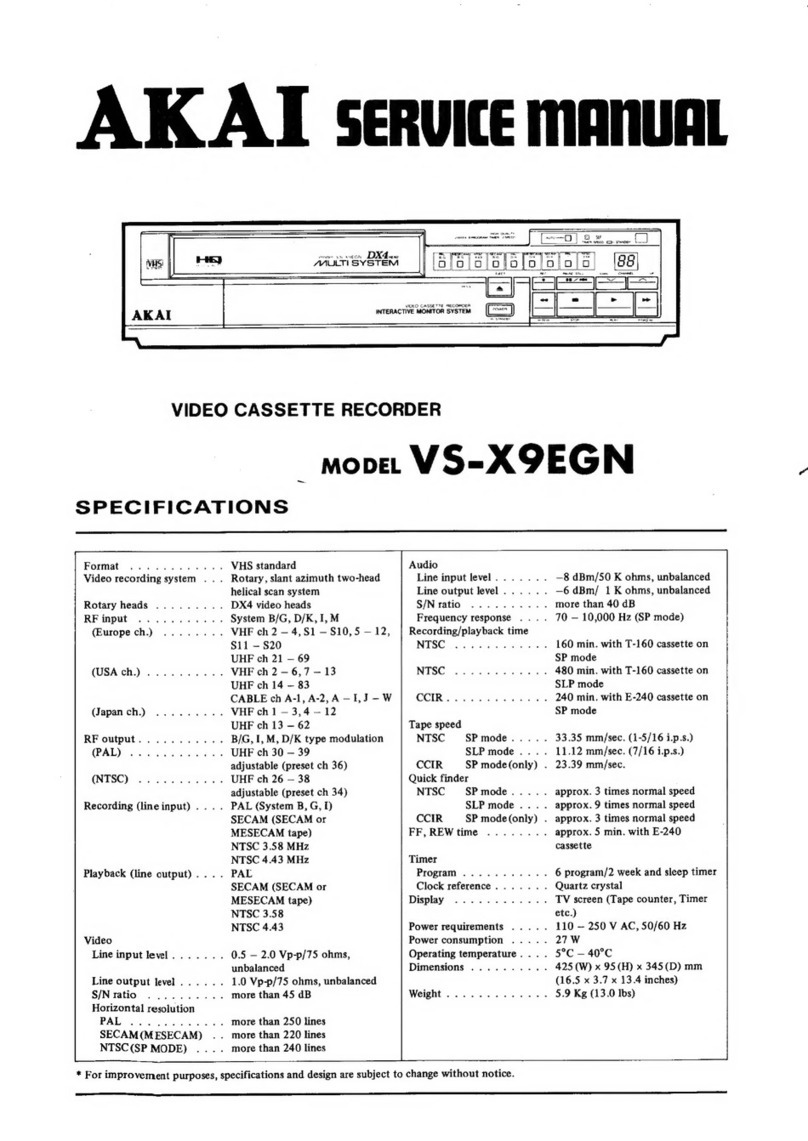
Akai VS-2EGN User manual

Noz2-s;,
ee
Sy
AKAT
Servite
manu
VIDEO
CASSETTE
RECORDER
move.
V
§=2EGN
(5
system)

8S.
:
Koni
Ca
TN
DER
ETRE
1000
BERLIN
35
‘wen.
Ra
Ja
area
Sana
-
Yosgad
-
Sa
VIDEO
CASSETTE
RECORDER
mopeLVS-2EGN(5
System)
SECTION
1
SERVICEMANUAL
.........---.+--++-
1
SECTION
2.
PARTSLIST
........--.
20522202
eeeeee
141
SECTION
3.
SCHEMATIC
DIAGRAM
............+++-
160

SAFETY
INSTRUCTIONS
SAFETY
CHECK AFTER
SERVICING
Confirm
the
specified
insulation
resistance
between
power
cord
plug
prongs
and
externally
exposed
parts
of
the
set
is
greater
than
10
Mohms,
but
for
equipment
with
external
antenna
terminals
(tuner,
receiver,
etc.)
and
is
intended
for
[C]
or
»
Specified
insulation
resistance
should
be
more
than
2.2
Mohms
(ground
terminals,
microphone
jacks,
headphone
jacks.
line-in-out
jacks
etc.)
PRECAUTIONS
DURING
SERVICING
2.
ower
D
Parts
identified
by
the
A\
symbol
parts
are
critical
for
safety.
Replace
only
with
parts
number
specified.
In
addition
to
safety,
other
parts
and
assemblies
are
specified
for
conformance
with
such
regulations
as
those
applying
to
spurious
radiation.
These
must
also
be
replaced
only
with
specified
replacements.
Examples:
RF
converters,
tuner
units,
antenna
selector
switches,
RF
cables,
noise
blocking
capacitors,
noise
blocking
filters,
etc.
Use
specified
internal
wiring.
Note
especially:
1)
Wires
covered
with
PVC
tubing
2)
Double
insulated
wires
3)
High
voltage
leads
Use
specified
insulating
materials
for
hazardous
live
parts.
Note
especially:
1)
Insulation
Tape
2)
PVC
tubing
3)
Spacers
(Insulating
Barriers)
4)
Insulation
sheets
for
transistors
5)
Plastic
screws
for
fixing
microswitch
(especially
in
turntable)
When
replacing
AC
primary
side
components
(transformers,
power
cords,
noise
blocking
capacitors,
etc.),
wrap
ends
of
wires
securely
about
the
terminals
before
soldering.
>
o>
Observe
that
wires
do
not
contact
heat
producing
parts
(heatsinks,
oxide
metal
film
resistors,
fusible
resistors,
etc.).
Check
that
replaced
wires
do
not
contact
sharp
edged
or
pointed
parts.
Also
check
areas
surrounding
repaired
locations.
Use
care
that
foreign
objects
(screws,
solder
droplets,
etc.)
do
not
remain
inside
the
set.

SECTION
1
SERVICE
MANUAL
TABLE
OF
CONTENTS
I.
SPECIFICATIONS
Ul.
OPERATING
PROCEDURE
1,
RECORDING
9°
PLAVYBAGR
asic
ees
ah
aici
Ill.
DISMANTLING
OF
UNIT
.......
IV.
CONTROLS
............-.5-
V.
PRINCIPAL
PARTS
LOCATION
VI.
VOLTAGE
CONVERSION
...........
VII,
CIRCUIT
DESCRIPTION
1,
GENERAL
2,
VS-2EGN
VIDEO
CIRCUIT
OPERATION
3,
SERVO
CIRCUIT
OPERATION
4,
MECHANISM
DRIVE
OPERATION
5,
OPERATION
CIRCUIT
6.
7
8
9
.
THE
POWER/SYSCON
CIRCUIT
.
AUDIO/VIDEO
PRE-AMP
CIRCUIT
.
BOOSTER
CIRCUIT
.
RF
CONVERTER
FUNCTIONS
AND
CIRCUITS
10.
TV
TUNER
(FRONT
END)
FUNCTIONS
AND
CIRCUITS
. .
11,
DEMODULATOR
FUNCTIONS
AND
CIRCUITS
VIII.
MECHANICAL
ADJUSTMENTS
...........-..--
1.
TENSION
LEVER
POSITION
ADJUSTME
2.
BACK
TENSION
ADJUSTMENT
...
Lara
pant
3.
CHECK
THE
VARIOUS
TORQUES
............-
IX.
REPLACEMENT
OF
VIDEO
HEAD
ASSEMBLY
X.
TAPE
TRANSPORT
ADJUSTMENT
1.
TAPE
GUIDE
HEIGHT
ADJUSTMENT
2.
GUIDE
ROLLER
HEIGHT
ADJUSTMENT
3.
AUDIO/CONTROL
HEAD
HEIGHT,
TILT
AND
AZIMUTH
ADJUSTMENT
.........-...--
103
4,
CONTROL
HEAD
POSITION
ADJUSTMENT
.
..
2...
6-6
eee
ee
eee
5,
ADJUSTMENT
OF
QUICK
FINDER
(REVIEW)
RUN
...
XI.
ELECTRICAL
ADJUSTMENT
1,
SERVO
P.C
BOARD
ADJUSTMENT
2.
VIDEO
(EGN)
P.C
BOARD
ADJUSTMENT
3.
EGN
P.C
BOARD
ADJUSTMENT
4,
AUDIO/PRE
P.C
BOARD
ADJUSTMENT
5.
DEMODULATOR
P.C
BOARD
ADJUSTMENT
XII.
VARIOUS
WAVEFORMS
AT
EACH
TEST
POINT
..
1.
SERVO
P.C
BOARD
.
.
2.
VIDEO
P.C
BOARD
3.
EGNP.C
BOARD
....
XII.
P.C
BOARD
TITLES
AND
IDENTIFICATION
NUMBERS
XIV.
COMPOSITION.OF
VARIOUS
P.C
BOARDS
For
basic
adjustments,
measuring
methods,
and
operating
principles,
refer
to
GENERAL
TECHNICAL
MANUAL.
Service
Manual
VS-2EGN

|.
SPECIFICATIONS
FORMAT
VHS
Standard
VIDEO
RECORDING
SYSTEM
Rotary,
slant
azimuth
two-head
helical
scan
system
RF
INPUT
System
B,
G
(PAL,
SECAM)
VHF
Ch
2
to
12
UHF
Ch
21
to
69
RF
OUTPUT
System
G
type
modulation
UHF
Ch
30
to
39
adjustable
(preset
to
Ch
36)
RECORDING
(LINE
INPUT)
PAL,
System
B,
G,I
SECAM,
System
B,
G
NTSC,
4.43
MHz
NTSC,
3.58
MHz
PLAYBACK
(LINE
OUTPUT)
PAL,
System
B,G,1
SECAM,
System
B,
G
SECAM,
System
L
NTSC,
4.43
MHz
NTSC,
3.58
MHz
VIDEO
LINE
INPUT
LEVEL
0.5
to
2.0
Vp-p/75
ohms
unbalanced
LINE
OUTPUT
LEVEL
1.0
Vp-p/75
ohms
unbalanced
S/N
More
than
43
dB
HORIZONTAL
RESOLUTION
More
than
250
lines
(PAL)
More
than
220
lines
(SECAM)
More
than
220
lines
(NTSC)
AUDIO
LINE
INPUT
LEVEL
—20
dBs/50
kohms
unbalanced
LINE
OUTPUT
LEVEL
—6
dBs/1
kohm
unbalanced
S/N
More
than
40
dB
FREQUENCY
RESPONSE
70
Hz
to
8
kHz
RECORDING
OR
PLAYBACK
TIME
240
min.
with
E-240
cassette
(PAL,
SECAM)
168
min.
with
E-240
cassette
(NTSC)
160
min. with
T-160
cassette
(NTSC)
TAPE
SPEED
23.39
mm/sec.
(PAL,
SECAM)
33.35
mm/sec.
(NTSC,
“standard
play”
mode
only)
QUICK
FINDER
PAL/SECAM
Approx.
7
times
the
normal
speed
(noise
bars
fixed)
NTSC
Approx.
5
times
the
normal
speed
(noise
bars
fixed)
FF.,
RWD
TIME
4
min.
with
E-240
cassette
TIMER
PROGRAMS
Nine
4-week-one
time
memory
programs
and
one
shut-off
pro-
gram
CLOCK
REFERENCE
Locked
to
power
line
frequency
(50/60
Hz)
DISPLAY
TV
screen
(Tape
counter,
Timer,
Clock
and
Calendar)
POWER
REQUIREMENTS
110
(100—120)/220
(200—240)V,
50/60
Hz
POWER
CONSUMPTION
45
watts
OPERATING
TEMPERATURE
5°C
to
40°C
DIMENSIONS
440(W)
x
133(H)
x
360(D)
mm
WEIGHT
10.5
kg
*
For
improvement
purposes,
design
and
specifications
are
subject
to
change
without
notice.
Service
Manual
VS-2EGN

it.
OPERATING
PROCEDURE
1,
RECORDING
1)
From
built-in
Tuner
(To
record
TV
programs)
SIGNAL
FOR
RECORDED.
TAPE
PAL
B/G
|
ve_
position
|
VS~2EGN
RECORDING
NOTE
I
SECAM
B/G
SECAM
B/G
)
(Mice
East
SECAM
(aiaate
East
SECAM
7
.
%
NOTE
1;
The
PAL
I
color
system
which
is
used
in
U.K
and
Hong
Kong
cannot
be
recorded
through
the
built-in
tuner.
2)
From
source
connected
to
VIDEO
IN
jack
SIGNAL
FOR
RECORDING
RECORDED
TAPE
PAL
PAL
B/G
B/G/H/1
POSITION
SECAM
B/G
(iicale
aie
SECAM
SECAM
B/G
(Migate
East)
SECAM
SECAM
L
(
Frenchy
SECAM
POSITION
NTSC
NTSC
3.58
3.58MHz
POSITION
Service
Manual
VS-2EGN
———————————
esse
3

2.
PLAYBACK
1)
On
TV
connected
to
RF
OUT
jack
RECORDED
TAPE
PAL
B/G
POSITION
TV
SECAM
B/G
(iiadle
East
SECAM
SECAM
B/G
POSITION
NTSC
4.43
POSITION
SECAM
L
POSITION
NOTE
2
SECAM
POSITION
NTSC
4.43
POSITION
SECAM
POSITION
%
NOTE
2:
Use
a
TV
which
can
receive
the
PAL
B/G
color
system.
If
a
TV
which
can
receive
the
PAL
|
color
system
in
used
no
sound
will
be
heard.
2)
On
TV
connected
to
VIDEO
OUT
jack
RECORDED
TAPE
SECAM
B/G
(Missle
East
SECAM
SECAM
L
(Eeeneh.
SECAM
NTSC
|
>
B/G
POSITION
PAL
B/G
POSITION
SECAM
U4
SECAM
L
POSITION
NTSC
3.58
POSITION
4.43
POSITION
Service
Manual
VS-2EGN
PAL
POSITION
SECAM
B/G
POSITION
SECAM
L
POSITION
NTSC
3,58
5-WAY
POSITION
NTSC
S
4.43
SeWay.
POSITION

I.
DISMANTLING
OF
UNIT
Ss
In
case
of
trouble,
etc.
necessitating
dismantling,
please
dismantle
in
the
order
shown
in
the
photographs.
Reassemble
in
reverse
order,
FRONT
PANEL
—:
‘SCREWS
1
4
CASSETTE
LID
SCREW
2 5
UPPER
CASE
‘SCREWS
SCREWS
3 6
-_oo
Service
Manual
VS-2EGN
5

Iv.
CONTROLS
ONOINBHARONS|
10.
11.
Fig.
4-1
Controls
(Front
View)
»
FUNCTION
“OFF/TIMER”
BUTTON
FUNCTION
“ON”
BUTTON
.
PRESET
(PS)
STATION
DISPLAY
}.
CASSETTE
HOLDER
.
PRESET
SELECT
(A)
BUTTON
DISPLAY
ON/OFF
(B)
BUTTON
TIMER/SLEEP
PROGRAM
NO.
BUTTON
}
CLOCK
BUTTON
|.
PRESET
BUTTON
EJECT
BUTTON
TAPE
TRANSPORTING
BUTTON
REWIND
(44
REW),
STOP
(ml
STOP),
FAST
FORWARD
(F.F
PP),
QUICKFINDER
REVERSE
(@)
QUICK
FINDER),
PLAY
(
®
PLAY),
QUICKFINDER
FORWARD
(QUICK
FINDER(@®D)),
RECORDING
(
@
REC),
COUNTER
“0”
STOP,
PAUSE
(
Il
PAUSE)
Service
Manual
VS-2EGN
Fig.
4-2
Controls
(Rear
View)
.
TRACKING
CONTROL
-
COMPARTMENT
FOR
THE
OPTIONAL
REMOTE
CONTROL
UNIT
RC-V202
.
COLOR
SYSTEM
SELECTOR
.
FINE
TUNING
(D)
BUTTON
.
COUNTER
RESET
(C)
BUTTON
»
AC
INPUT
SELECTOR
.
POWER
ON/OFF
SWITCH
.
RF
CONVERTER
CHANNEL
(CH.)
ADJUSTMENT
(ADJ.)
HOLE
ANTENNA
(ANT.)
IN
JACK
.
RF
OUT
JACK
.
AUDIO
JACK
.
VIDEO
IN
JACK
.
VIDEO
OUT
JACK
.
REMOTE
PAUSE
JACK
j.
AC
INLET
|.
TV/VIDEO
BUTTON
(EA
MODEL
ONLY)

V.
PRINCIPAL
PARTS
LOCATION
1.
8
3.
4.
5.
6.
hh
8.
a.
10.
TAs
12.
13.
14,
15,
16.
17.
18.
19.
20.
21.
22.
23.
24.
25.
25
@4
OPERATION
P.C
BOARD
V1009A5170
FUNCTION
ON
SWITCH
FUNCTION
OFF/TIMER
SWITCH
DIGITAL
DISPLAY
PRESET
SELECTOR
(A)
SWITCH
DISPLAY
ON/OFF
(B)
SWITCH
TIMER/SLEEP/PROGRAM
NO.
SWITCH
CLOCK
SWITCH
PRESET
SWITCH
EJECT
SWITCH
QUICK
FINDER
REVERSE
SWITCH
REWIND
SWITCH
PLAY
SWITCH
STOP
SWITCH
QUICK
FINDER
FORWARD
SWITCH
FAST
FORWARD
SWITCH
PAUSE
SWITCH
TRACKING
VOLUME
COUNTER
AUTO
“0”
STOP
SWITCH
REC
SWITCH
LED
P.C
BOARD
V1009D5320
SYSTEM
SWITCH
FINE
TUNING
(D)
SWITCH
COUNTER
RESET
(C)
SWITCH
BACK
UP
BATTERY
(6)
O®2®O®
OOMQO®Q
YO
OOGL
|©
2
Bea)
BIg
Fig.
5-1
Parts
Location
(Front
View)
Service
Manual
VS-2EGN

YV@2OSO®H
©
ODMOQD
WO
W
&
1, S,
IMPEDANCE
ROLLER
2.
AUDIO/PRE
P.C
BOARD
V1009A5180
3.
DRUM
HEAD
BLOCK
4,
DEMODULATOR
P.C
BOARD
5.
TV
TUNER
UNIT
6.
CAPSTAN
MOTOR
7.
ANTENNA
BOOSTER
8,
MECH
DRIVE
P.C
BOARD
V1009A519B
9,
RF
CONVERTER
10.
POWER
FILTER
P.C
BOARD
V1009D5210
11,
POWER
TRANSFORMER
12.
POWER
&
SYSCON
P.C
BOARD
V1009A519A
13.
SOCKET
FOR THE
OPTIONAL
REMOTE
CONTROL
UNIT
RC-V202
14.
TAKE
UP
REEL
15.
SUPPLY
REEL
16.
PINCHROLLER
17.
FULL
ERASE
HEAD
18.
AUDIO/CONTROL
HEAD
Service
Manual
VS-2EGN

.
DRUM
MOTOR
,
LOADING
SWITCH
A
EJECT
SWITCH
LOADING
MOTOR
REC.
SAFETY
SWITCH
LOADING
SWITCH
B
REEL
MOTOR
.
INTERMEDIATE
P.C
BOARD
V1009A519C
.
PLUNGER
.
CAPSTAN
FLYWHEEL
.
CAPSTAN
MOTOR
.
TRACKING
VOLUME
.
EGN
P.C
BOARD
.
SERVO
(EGN)
P.C
BOARD
.
VIDEO
(EGN)
P.C
BOARD
Fig.
5-3
Parts
Location
Service
Manual
VS-2EGN
9

Vi.
VOLTAGE
CONVERSION
POWER
:
ON
OFF
AC
INPUT
—
[asm
nov
|
(ee
g
110/220
50Hz~
pana
2)
~“@})
CONVERTER
ay
|
RF
ICH.
ADJ.
HOLE
Fig.
6-1
Voltage
Conversion
Power
requirements
for
electrical
equipment
differ
from
area
to
area.
The
operating
voltage
of
VS-2EGN
is
pre-
set
to
220V.
Before
connecting,
check
that
the
AC
IN-
PUT
selector
on
the
rear
panel
is
set
to
the
voltage
for
your
area:
110V,
50
Hz
for
other
countries.
If
the
AC
INPUT
is
not
set
for
your
area:
1.
Confirm
that
the
POWER
Switch
on
the
rear
panel
is
set
to
OFF.
2.
Confirm
that
the
POWER
Cord
is
disconnected.
3.
Move
the
AC
INPUT
selector
with
a
screwdriver
so
that
the
marker
is
above
the
voltage
for
your
area.
Service
Manual
VS-2EGN

Vil.
CIRCUIT
DESCRIPTION
Iscanning
lines)
Line
So
‘
~
Subcarrier]
,,
at
eT
und
Video
Colour
Modulation
|
Phase
of
Burst
TV
system
iyith
respec
ay
TV-CH
frequency
spectrum
Modulation}
|
Modulation
System
aed
system
|
With
respect
to
B-Y
:
fp
fs
Br
B
(ur)
Picture
carrier
Sound
corrier
G
O75
0
5.5
MHz
G
G|
PAL
|
4.433619
g
(UHF)
3
4
2
a
Sry
¥) se
H
eae
H
H
s
|#
(UHF)
1.25
°
5.5
MHz
g
625/50
15,625
FM
4
g
|
Pohas
ke
[ash
=
Ele,
Go
|
Sn
3
[sf/s/s/sfs
a
board
a
ee)
I I
I
g
2
1250
6.0MHz
3
4
g
2
a
=
2|
2/88]
3
D
D
s
(VHF)
&
075
0
6.5
MHz
K K
(UHF)
Positive
B
for:
G
B
AM
BY
SECAM
_dhoe2s
FM
No
burst
125.0
6.5MHz
®
har
NEGATIVE
15,750
Sane
M
525/60
|
8M
64
FM
}——=/M)_Nrsc
|
3.579545)
7°)
—180°
(Colour)
as
PAL
0.75
0
4.5MHz
Fig.
7-1
World
TV
Systems
and
Colour
Systems
1,
GENERAL
11
WORLD
TELEVISION
AND
COLOUR
SYSTEMS
eT
Re
m i
The
VS-2EGN
is
capable
of
recording
and
playback
of
Refer
to
Fig.
7-1.
television
signals
shown
below,
and
is
a
high
grade
multi-
For
example,
in
the
case
of
SECAM
B/G
which
is
call-
function
model.
ed
Middle
East
SECAM,
monochromatic
signals
follow
@
Recording/playback
of
PAL
BG
the
CCIR
system,
while
colour
signals
are
of
the
SECAM
©®
Recording/playback
of
SECAM
BG
system.
©
Recording/playback
of
NTSC
4.43
(line
video
re-
cording
only)
@
Recording/playback
of
NTSC
3.58
(line
video
re-
cording
only)
©
Playback
of
SECAM
L
At
present,
there
are
various
television
systems
in
the
world.
Television
signals
which
can
be
recorded
or
re-
produced
by
the
VS-2EGN
and
television
systems
in
the
world
are
described
below.
‘Service
Manual
VS-2EGN

1-2
RADIO
FREQUENCY
HEAD
OF
VS-2
VS-2
DEMODULATOR
Receivable
broad
|
VIDEO
Receivable
Broadcast
cast
system
|IF
channels
Demodulated
signal
Model
aaa
Country
OUND
IF]
VAF-L
|
VHe-
|
UHP
Video
Sound
(Mtn)
EG
BIGPAL
|
38.9
va
B/G
PAL
Germany,
Singapore
EGN
|
B/GSECAM
oe
aaal
24
|
S12]
21-69
|
seca
Middle
East
Country
1
PAL
39.5
UK.
oe
(HF
only)
335
|
7
So)
/Ine?
|
|
th
PAL
Hong Kong
B/G
PAL
Mi~M10
B/G
PAL
.
EO
B/G
SECAM
BG
r
Fer
5~12
|
21~69
|
B/G
Fake
a
(CATV)
:
UI~U10
SECAM
B/G
PAL
:
EA
ahora
e685
o~s
|
SA~11
|
21~69
|
BIG
AM
||
ee
ada
31.375
SEEM
a
TPAL
38.9
-
ES
|
yur
g
VPA)
Seg
|
~~
|
Avtd
|
zion
|
rPAL
South-Africa
LSECAM
ao
.
bs
Wide
video
s
L
SECAM
see
on
nears
France
33,
compared
to
BIG
Fig.
7-2.
VS-2
Demodulator
VS-2
RE
Convertor
Moaer
|
Television
isgicie
SbeC
airs
Output
|
Video
modu-
system
channel
|
lation
polarity
‘
cus
EA
B
VHF
cH4
°
+55
ile
NEGATIVE
ot
EG
‘
cH30
EO
é
DAF
~39
BGN
sts
variable
|
$
EK
;
cH30
ES
WHE:
variable
3
5.596
BosiTVe
-
|
cxs0
s
L
ue
~39
5
65
|
variable
Fig.
7-4
RF
Converter
Types
for
VS-2
As
might
be
known
from
Fig. 7-1,
the
frequency
spec-
trum,
etc.
of
the
television
channel
vary
from
TV
system
to
TV
system.
Accordingly,
the
tuner
unit
of
the
video
cassette
recorder
(VCR)
which
receives
TV
broadcasts
is
classified
as
shown
in
Fig.
7-2
according
to
the
model
code
letters.
VS-2EGN
has
a
built-in
tuner
for
Model
EG.
Fig.
7-3
shows
the
types
of
AKAI
VTR
available
and
the
transmission
channels
used
in
major
countries.
The
types
of
RF
converter
are
classified
as
shown
in
Fig.
7-4,
which
shows
that
the
RF
converter
for
the
G
system
is
used
for
the
VS-2EGN.
This
type
of
RF
con-
verter
is
also
used
for
models
EG
and
EO.
12
2
g
2.
8
Z
2
B
<
a
y
S
a
Zz
eo
Fd
4
S
s
OTs
g
318
ee
oO
=
st
>.
2
st
st
5
BTS]
272]
eS
B
ete
wel
07S
2
2
rl
i
gl?
g]*
o
is) is)
&
is)
is}
ba
ate
8
a)
|
]*
aye
& °
is)
=
=)
q|
x
€
©
~
x x
ic
J
ra
a
2/8
& 3
Els
8 8
3
g
a
le
a
«|
a
ey
= - a
a o
“
a
Slo
elo
lel
Slel
ale)
ele
3
Ss
Ser
8
g|
éle
Els)
ele
ele]
ele
éle
Is}
le
Ele)
Sle
2
3
3s
Ss
8]
[s
3
3
ics
3
S
S-St4s
>
3
S
s
or
FY
23!
ls
=
Fs
=
Es
Fs
@
(gz
|e
[8
FA
z
|
E
BB)
|e
& = z
FA
5
Bz]
|S
5
5
5
5
5
S
eye
=
als
S]a
as
<
3
=
z
-
27a
5
S
z
gle
3
=
8)
nd
“
2
278
Ble
ale
2
8
Ny
a
21S
s
sT&
gfe)
aya
q
ays]
te}
Sys
x78
Rai]
soe
é=|
3
Bi
ist
Stal
o
i
ayal
©
2
5
gz
S|
8
8
a
oe
&
z
=
z
4
2 a
Es
=
Zle
|
zl.
1
x
a
2
Ble]
Os}
Sg]
Sls
élz
Clg)
Cie
Ste}
Sls
3
5
ef=
of
=
x
a
a
s
<<
2
aie
z
28
4,8
ls
als
oT=
zie
mis @is
eo!
gle
ee
or
|
oF
416
Bly
g
a
es
°
Zl.
lect
aoe
oun
-
Rel,
See
al
Ss
SS!
|S
sy8/s
sz]=
2f%isy
73/5
+78
=|
|S
S56]
/8
=
sé
bl
[sa
ay
isa
ca
g
2
ls|z
3
as
at
BS
6|_l£8
>|_
le
2
Zal_lz
Z2§ly
Blyl2
Cls
Se
AS
+E
I
lee
: £
>
>
ES
>
ES
> >
2b
<
g
3
8
z
3
=
p
a
<
oS
“za
cA
&
Zz
4a
8
23
4
2
5
2
az
<
ae
5
4
RZ
a
<
Z
g
st
iy
< <
By
iA
g
I
Ft
aA<
Oo}
2/42)
2
/3<}|
4]
6
3/28)
a
/5°)
&
88
5S
pO
a
a
3
=
=
Zz
a
&
oO
=
:
Fv]
<
fo)
9 &
2.
-
BE
=
7
a
8 5 8 2
g
500
600 700
800 900
Frequency
(MHz)
400
300
Fig.
7-3.
Types
of
AKAI
VTR
available
and
Transmission
200
100
20
Channels
used
in
Major
Countries
UHF-
‘VHF:

1-3.
RECORDING/PLAYBACK
FUNCTION
OF
VS-2EGN
Signal
Recorded
on
tape
Recordable
Video
Signal
a
Playback
Video
(With
built-in
tuner)
Colour
|,
Signal
Frequency
spectrum
on
tape
proce
gnal
“
Syne
White
CH-1
no
4
os
c
tip
peak
change
PAL
CH-2
extra
B/G
90°
lag
°
5
MHz
|
O
0.627
3.8
4.8
MHz
|
every
1H
°
3
443MHz
c
—M
fos
son
i
FM
CH-1
fos for
B/G
Both
no
0
5
MHz
|
0.664
3:8
48
MHz
|
change
° 3
MHz
foe
2
4,25MHz
O81
fos
|
4.25MHz
for
:
4.40625
MHz
for
°
4.40625MHz
(Through
Line
input)
4.43
CH-1
no
PAL
c c
change
B/G
CH-2
extra
T
90°
lai
HT
|
o
Smuz
|
0627
Be
48M
|
veyin
|
O
3
4,43MHz
Cc
FM
fos
for
FM
CH-1
fos
for
SECAM
|
|
|
eu
CH.2
B/G
3
t
Both
no
ce)
0.66
3.8
4,8
MHZ
°
3
MHz
fos
:
4.25MHz
0.81
change
fos
©
4,.25MHz
for:
4.40625MHz
os
for
:
4.40625
MHz
FM
foe
for
SECAM
L
Recordable
°
fos
>
4,25MHz
for
:
4,40625MHz
CH-1
extra
358
90°
advance
NTSC
every
1H
|
|
/
FM
3.58CH-2
°
°
4.2
Miz
0.629
34
44
MHz
|
extra
90°
lag)
3
3.58
MHz
BOS
every
1H
4143
NTSC
¢
0
MHz
co)
3
4:43
MHz
Fig.
7-5
Recording/Playback
Function
of
VS-2
EGN
Service
Manual
VS-2EGN

Refer
to
Fig.
7-5
Recording/Playback
Function
of
VS-2
Recordable
TV
signals
from
built-in
tuner
PAL
B/G
SECAM
B/G
Recordable
TV
signals
from
line
input
PAL
B/G/H/I
SECAM
B/G
(Middle
East
SECAM)
SECAM
L
(French
SECAM)
NTSC
3.58
(standard
NTSC)
NTSC
4.43
(modified
NTSC)
1-4
SELECTION
OF
SIGNAL
SYSTEM
As
shown
in
Fig. 7-6,
the
operation
panel
of
Model
VS-2EGN
has
an
LED
display
unit
(AUTO:
green,
the
rest:
red),
the
there
is
a
SYSTEM
selector
switch
below
it.
The
SYSTEM
switch
permits
manual
system
selection.
Normally,
reset
is
effected
at
Function-ON,
and
the
system
selects
the
AUTO
mode,
which
is
detected
by
a
microcomputer
and
displayed.
Accordingly,
the
SYS-
TEM
switch
is
not
used.
1-4-1
SYSTEM
DISPLAY
IN
AUTO
MODE
(Recording
Electronic-to-Electronic
(EE)
Mode)
The
SECAM
L
signal
from
the
line
input
is
recorded
as
a
SECAM
B/G
signal
on
the
tape
(system
employing
count
down
of
the
SECAM
colour
signal
similar
to
the
PAL
system
operation),
NTSC
4.43
signal
is
recorded
on
the
tape
as
an
NTSC
3.58
signal.
Playback
signals
vary
from
each
other,
and
a
3-system
or
a
S-system
television
is
required.
The
television
should
be
set
so
that
the
system
display
at
the
front
of
VS-2
EGN
becomes
the
same
mode
as
the
displayed
signal.
For
details,
refer
to
I].
Operating
Procedure.
o
Cat
8/6
Ostcam
6/6
Ontsc
4.43
CISECAM
L
Onrsc
3.58
SYSTEM
Fig.
7-6
System
Display
Unit
INPUT
LED
VIDEO]
PAL
SECAM
B/G
|
NTSC
4.43
|
SECAML
|
NTSC
3.58
AUTO
e
e
e
e e
PAL
B/G
°
SECAM
B/G
e
°
NTSC
4.43
e
SECAML
-
=
o
NOTE
1
-
NTSC
3.58
e
NOTES:
1.
Since
the
SECAM
L
signal
is
recorded
on
the
tape
as
a
SECAM
B/G
signal,
SECAM.
B/G
indicator
lights
in
the
LED
display
unit.
2.
When
there
is
no
input
video
signal,
the
AUTO
indicator
alone
lights.
(Playback
Mode)
TAPE
PAL
SECAM
B/G.
NTSC
SECAM
L
LED
AUTO
e
e e
e
PAL
B/G
SECAM
B/G
e
NTSC
4.43
=
= =
=
NOTE
1
SECAM
L
°
NTSC
3.58
e
NOTE:
1.
When
it
is
desired
that
signals
are
reproduced
in
NTSC
4.43,
use
the
manual
operation
procedure.
14
‘Service
Manual
VS-2EGN

——
1-4-2
SYSTEM
DISPLAY
IN
MANUAL
MODE
For
selecting
the
system
manually,
press
the
SYSTEM
switch
the
appropriate
number
of
times
until
the
desired
system
is
selected.
(Recording
EE
Mode)
No.
of
4g]
Function
|
1sttime
|
2nd
time
|
3rd
time
|
4th
time
|
Sth
time
|
6th
time
LED.
ON
AUTO
e e
PALB/G
.
nore
s
SECAM
B/G
e
NOTE
2
NTSC
4.43
e
SECAM
L
NOTE1
=
=
=
=
=
NTSC
3.58
e
NOTES:
1.
SECAM
L
cannot
be
selected
in
the
Recording
EE
mode.
2.
When
all
LEDs
are
OFF,
the
mode
is
625
lines/50
Hz
monochromatic
mode.
3.
At
the
6th
time,
the
LED
display
returns
to
AUTO.
However,
when
there
is
no
video
input
to
the
VCR,
‘AUTO’
does
not
light.
The
LED
display
lights
a
colour
video
signal
is
connected.
(Playback
Mode)
No,
of
times
LED
AUTO
e e
NOTE
2
PALB/G
SECAM
B/G
NTSC
4.43
SECAM
L
e
NTSC
3.58
eee
Ist
time
|2nd
time
|
3rd
time
|
4th
time
|
5th
time
|
6th
time
|
7th
time
NOTE
1
NOTES:
1.
When
all
LEDs
are
OFF,
the
mode
is
625
lines/50
Hz
monochromatic
mode.
2.
At
the
7th
time,
the
LED
display
returns
to
AUTO.
Since
a
video
signal
is
always
present
at
the
video
judge
(VJ)
output
during
playback,
the
LED
display
does
not
go
off.
1-5
VIDEO
PRESENT/ABSENT
JUDGEMENT
[
PB
ON
Tuner
receiving
no
signal
picture
1
P.B
Picture
Loading
1
2-6
sec
time
Fig.
7-7
In
VS-2
EG/EO/EX/ES/EA/S,
it is
so
controlled
that
even
when
no
wanted
video
signal
is
present,
a
video
signal
is
made
to
be
present
in
the
CUE/REVIEW
mode
of
playback
only.
Accordingly,
at
the
time
of
CUE/
REVIEW
playback
of
unrecorded
tape,
etc.,
a
noise
pic-
ture
appears.
On
the
other
hand,
no
noise
picture
ap-
pears
during
normal
playback
or
in
the
recording
E-E
‘Service
Manual
VS-2EGN
mode,
since
switching
to
the
internal
oscillator
takes
place
when
no
video
signal
is
present.
In
VS-2EGN,
no
video
judgement
is
performed
in
any
of
the
playback
modes
including
CUE/REVIEW.
That
is,
control
is
exercised
to
ensure
an
always
video
signal
present
condition.
For
this
reason,
the
following
special
picture
changes
occur.
15

In
the
cases
of
tuner
reception
(when
the
converter
is
not
connected
to
the
VIDEO
LINE
IN)
and
no
signal.
1)
With
no
signal,
the
E-E
picture
is
a
gray
picture
from
the
internal
oscillator.
2)
When
the
PB
button
is
depressed,
a
tuner
recep-
tion
signal
appears
regardless
of
whether
or
not
a
pic-
ture
is
received.
*1
3)
The
condition
of
2)
continues
until
the
end
of
load-
ing
and
in
addition
for
about
2.6
seconds,
and
then
the
TV
display
is
changed
to
the
playback
signal
picture.
2.
VS2-EGN
VIDEO
CIRCUIT
OPERATION
VS-2EGN
can
perform
the
recording
and
playback
of
the
following
signals.
1)
Recording
and
playback
of
PAL
B/G
(from
Built-in
Tuner
to
RF
OUT)
2)
Recording
and
playback
of
SECAM
B/G
(from
Built-
in
Tuner
to
RF
OUT)
3)
Recording
and
playback
of
NTSC
3.58M
(from
Line
in
to
Line
Out)
4)
Recording
and
playback
of
NTSC
4.43M
(from
Line
in
to
Line
Out)
5)
Playback
of
SECAM
L
(to
LINE
OUT)
Operation
of
the
above
five
systems
will
now
be
des-
cribed.
Since
the
systems
differ
in
the
filter
characteris-
tics,
PAL
is
mainly
described,
for
the
luminance
system
section,
and
for
other
sections
only
points
differing
from
PAL
are
described.
The
chrominance
(CHROMA)
circuit
is
described
by
dividing
it
into
the
following
four
sections
according
to
the
nature
of
its
signals.
1)
PAL
B/G
and
NTSC
4.43
recording
and
playback
2)
SECAM
B/G
recording
and
playback
3)
NTSC
3.58
4)
SECAM
L
playback
2-1
LUMINANCE
(Y)
RECORDING
AND
PLAYBACK
2-1-1
E-E
SYSTEM
(PLEASE
REFER
TO
THE
VIDEO.
SCHEMATIC)
A
PAL
B/G
or
SECAM
B/G
signal
from
the
tuner
(de-
modulator)
or
alternatively
a
video
signal
from
LINE
IN
is
terminated
at
R1
(75),
fed
to
VR-11
(E-E
level)
for
E-Elevel
adjustment
and
fed
to
VIDEO
AMP
IC6
(HA11703)
pin
O,
and
output
from
pin
.
Quasi
V
pulse
(VP)
is
added
by
TR32
only
while
in
the
trick-
play,
ie.,
CUE,
REVIEW,
and
PB/PAUSE.
Then,
the
signal
enters
pin
and
is
amplified.
Next,
the
signal
is
output
from
pin
,
and
enters
IC5
(HD14053BP)
pin
©.
Since
the
video
signal
is
present
and
12
VJ
line
of
the
video
judge
(VJ)
circuit
in
the
servo
circuit
is
‘H’,
the
signal
is
output
to
pin
and
then
the
character
signal
is
added
at
TR8
by
the
output
Video
on
Word
(VOW)
from
the
mi-com
of
the
operation
PC
board.
Now,
the
video
signal
is
output
to
LINE
VIDEO
OUT
via
TR2,
and
it
is
fed
to
the
RF
converter
from
the
VID
terminal
through
RL2
(LCB-56)
and
TR6.
In
summary,
this
sig-
nal
flow
represents
the
E-E
system.
16
‘Service
Manual
VS-2EGN
*1:
In
the
models
other
than
VS-2EGN,
1)
con-
tinues
to
the
part
of
2),
but
in
Model
EGN,
the
PB
12V
control
line
is
used
to
control
all
play-
back
modes.
Since
the
PB
12V
is
output
con-
currently
with
the
depression
of
the
PB
but-
ton,
the
condition
2)
appears.
2-1-2
RECORDING
SYSTEM
In
accordance
with
the
description
of
the
E-E
system
in
Section
2-1-1,
the
video
signal
is
applied
to
IC5
(HD
14053BP)
pin
,
and
the
character-added
video
is
applied
to
pin
(2).
The
signal
from
pin
(1)
is
output
through
ICS
output
pin
(©)
at
the
normal
time,
ie.,
when
pin
(©)
is
‘H’,
and
this
output
signal
is
fed
to
the
video
head.
However,
during
the
period.
when
INS
LINE
is
kept
‘H’
by
the
mi-com
of
the
operation
PC
board,
pin
is
kept
at
‘L’
via
the
converter
TR29,
and
the
input
from
pin
@
is
output
to
pin
®.
That
is,
the
character-
added
video
signal
is
supplied
to
the
video
head.
ICS
pin
@®
output
is
branched
to
the
LPF
consisting
of
FL3,
and
the
LPF
consisting
of
FL5.
The
—3
dB
point
of
FL3
is
3.0
MHz,
and
is
3.3
MHz
for
FLS.
In
the
state
where
a
PAL
(B/G)
or
SECAM
(B/G)
signal
is
being
recorded,
ICS
pin
is
at
‘H’
level.
Since
pin
is
connected
to
NT-L,
only
the
luminance
com-
ponent
of
the
video
signal
which
has
passed
through
the
LPF
is
output
to
pi
3.
The
output
of
pin
(4)
is
supplied
to
IC1
(AN6310)
pin
@),
and
is
output
to
pin
@3).
During
that
time,
the
sig-
nal
is
subjected
to
AGC
(automatic
gain
control),
and
the
deviation
(1.0
MHz)
of
the
frequency
modulation
circuit
in
the
next-stage
is
determined
by
VR8
located
between
pins
and
©.
The
output
of
the
VIDEO
AMP
circuit
(pin
@®
—
pin
)
passes
through
the
non-linear
emphasis
circuit.
The
amount
of
emphasis
is
determined
by
TR12
and
TR16
when
there
is
an
NTSC
signal.
Then,
the
signal
enters
pin
48
and
is
subjected
to
frequency
modu-
lation.
Since
TR13
connected
to
pins
@®/
@
be-
comes
ON
in
the
modes
other
than
NTSC,
the
FM
carrier
frequency
is
changed.
Dark
Clip
VR7
is
connected
to
pin
(2),
while
White
Clip
VRS
is
connected
to
pin
(Q).
The
frequencies
of
White
Clip,
Dark
Clip,
and
Deviation
are
as
follows:
Mode}
PAL
B/G,
SECAM
B/G
|
4.43,
3.58
NTSC
WHITE
CLIP
5.4
MHz
5.0
MHz
PEAK
WHITE
4.8
MHz
4.4
MHz
SYNC
TIP
3.8
MHz
3.4
MHz
DARK
CLIP
3.4
MHz
3.0
MHz

The
frequency-modulated
Y
signal
(FMY)
from
IC1
pin
(©)
is
directed
to
pass
through
the
HPF
consisting
of
FL1
(1.4
MHz
at
—3
dB
point)
so
as
to
prevent
interference
with
the
low
frequency
converted
CHROMA
(mentioned
later).
Thereafter,
the
signal
is
controlled
at
VR4
(Y
REC
LEVEL),
mixed
with
the
low
frequency
converted
CHROMA,
passed
through
the
REC
Signal
Inter-Board
Connection
to
the
Audio/Pre
P.C
Board,
fed
to
the
PRE
AMP
circuit,
and
supplied
to
the
video
head
through
the
emitter
follower
(TR10)
and
the
constant
current
buffer
(TR8/9).
Since
TR5
and
TR6
are
grounded
by
REC
12V
during
recording,
a
closed
circuit
of
REC
current
is
formed
via
R43,
and
VIDEO
data
is
recorded
on
the
tape.
2-1-3
PB
SYSTEM
Since
TR4
of
the
pre-amp
circuit
goes
ON
during
play-
back,
the
PB
VIDEO
signals
(FMY
+
Low
Frequency
Converted
Chroma)
from
the
video
heads
1
and
2
are
1)
DROP
OUT
Pulse
Generator
(Refer
to
Fig.
7-8)
os
EEI2V
R58
100K
1c20)
At
the
time
of
a
drop-out
occurs,
IC2
pin
(0)
becomes
‘L’,
causing
1C3
(wH741TC)
pin
G)
to
become
‘L’.
Since
C46
(1uF/S5OV)
has
only
just
started
to
discharge
pin
@
does
not
become
‘L’.
That
is,
the
output
is
‘L’.
D3
is
for
operation
stop
in
the
E-E
mode.
The
output
of
IC2
pin
()
is
fed
to
the
double
limiter
circuit
in
which
the
signal
is
divided
into
two.
First
it
is
directed
to
the
HPF
composed
of
C48, R62,
and
C47,
amplified
at
TR7,
phase
corrected
at
C39
and
R37,
amplified
at
TR15,
and
fed
to
IC4
(TA7060AP)
pin
@
.
The
signal
is
amplitude-limited
at
the
1st
limit-
et
between
pin
(1)
and
pin
(4),
and
then
applied
to
the
emitter
of
TR18.
Secondly,
the
output
of
IC2
pin
®
is
directed
to
the
LPF
(4
MHz
at
—3
dB
point)
composed
of
R80
and
C57,
and
applied
to
the
base
of
TR18.
At
the
collector,
this
signal
appears,
mixed
with
the
first
signal
which
is
applied
to
the
emitter.
After
being
phase-corrected
at
TR9,
L10,
and
R47,
the
‘Service
Manual
VS-2EGN_
supplied
to
IC2
(AN6320N)
pins@)and(5)
After
going
through
pins
3)
/G),
PB
VIDEO
signals
of
CH-1
and
CH-2
are
selected
by
the
Amplifier
Switching
Pulse
which
connects
them
to
pins
and
©,
after
the
overlap
portions
have
been
cut
off.
The
outputs
from
pins
and
(9)
are
mixed
on
the
way
to
pin
a,
and
the
mixture
flows
to
pin
()
after
going
through
the
MIX
AMP,
and
then
to
the
video
PC
board
as
a
PB
PRE
OUT
through
the
emitter
follower
(TR7).
On
the
video
board,
the
PB
signal
from
the
pre-amp
is
directed
through
the
HPF
(1.4
MHz
at
—3
dB
point)
consisting
of
C1,
5,6,
R10,
11,
and
L1.
Only
FMY
is
extracted
there,
fed
to
the
5.8
MHz
peaking
circuit
composed
of
L35,
C203,
and
TR3,
subjected
to
the
phase
correction
at
C15,
16
and
L6,
fed
to
pin
(3
of
IC2
(HA11718)
sub-
jected
to
AGC;
and
then
output
from
pin
()
of
IC2.
When
there
is
a
drop-out,
the
signal
1H
earlier
is
output
from
pin
()
and
supplied
to
pin
(}
by
DL1
(64
us
delay).
1
see
=
|
THRESHOLD
! I
i
©
‘
Fig.
7-8
DROP
OUT
Pulse
Generator
signal
is
fed
to
IC6
(HA11703)
pin
(4)
via
the
emitter
follower
of
TR39.
After
being
amplitude-limited
and
FM-demodulated
on
the
way
from
pin)
to
pin@)
the
signal
is
directed
through
the
respective
filters
of
FL8
(PAL),
FL6,
7
(NTSC),
and
FL9,
10
(SECAM),
and
fed
to
IC7
(HD14066BP)
pins,
@),
Now,
if
both
con-
trol
signal
lines
3N-H
and
3L-H
from
the
servo
circuit
are
‘L’
(PAL
mode),
the
signal
passes
from
IC7
pin
(1)
to
pin
(),
is
directed
to
the
non-linear
de-emphasis
circuit
composed
of
TR34,
L20,
C91,
D8,
and
D9,
phase
cor-
rected
at
L11
and
C102,
then
fed
to
IC6
pins
@
and
®,
and
output
from
pin
©.
PB
CHROMA
is
supplied
to
pin
®
and
mixed
there.
The
output
of
pin
(16)
passes
through
VP
ADD
of
TR32.
17
Table of contents
Other Akai VCR System manuals

Akai
Akai SHOWVIEW VS-G245EDG User manual

Akai
Akai VS-K203M-E7 User manual

Akai
Akai AVR250 User manual

Akai
Akai VS-J4600 User manual

Akai
Akai VS-G415EA User manual

Akai
Akai VS-G205 User manual

Akai
Akai VS-G242EA User manual

Akai
Akai VS-X9EGN User manual

Akai
Akai VS-K606N-E3(S) User manual
Akai
Akai VS-606EA User manual