manuals.online logo
Brands
  1. Home
  2. •
  3. Brands
  4. •
  5. Akai
  6. •
  7. VCR System
  8. •
  9. Akai VS-X9EGN User manual

Akai VS-X9EGN User manual

Other Akai VCR System manuals
Akai VS-G205 User manual

Akai

Akai VS-G205 User manual

Akai VS-606EA User manual

Akai

Akai VS-606EA User manual

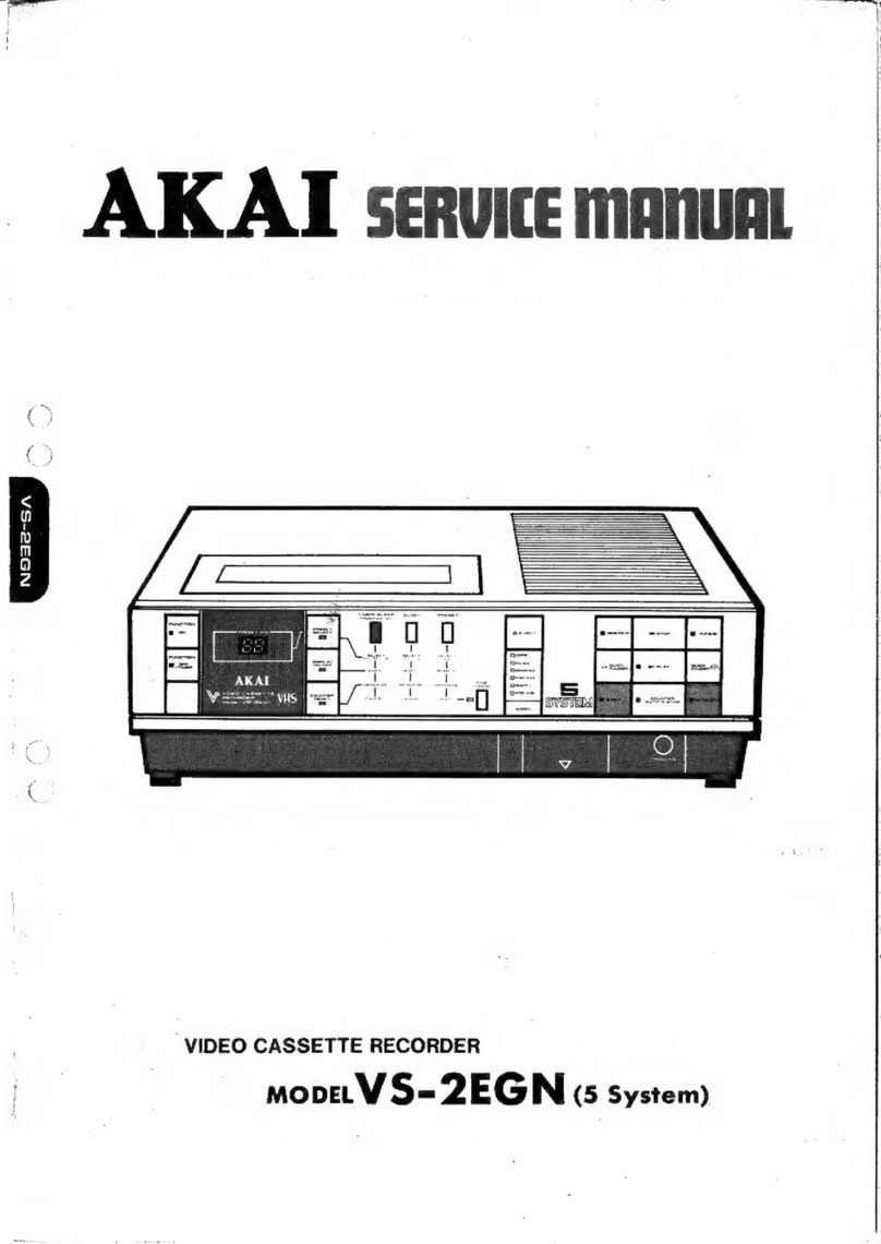
Akai VS-2EGN User manual

Akai

Akai VS-2EGN User manual

Akai AVR250 User manual

Akai

Akai AVR250 User manual
Akai VS-K606N-E3(S) User manual

Akai

Akai VS-K606N-E3(S) User manual

Akai VS-G415EA User manual

Akai

Akai VS-G415EA User manual
Akai SHOWVIEW VS-G245EDG User manual

Akai

Akai SHOWVIEW VS-G245EDG User manual

Akai VS-J4600 User manual

Akai

Akai VS-J4600 User manual

Akai VS-G242EA User manual

Akai

Akai VS-G242EA User manual

Akai VS-K203M-E7 User manual

Akai

Akai VS-K203M-E7 User manual
Popular VCR System manuals by other brands

RCA VR678HF user guide

RCA

RCA VR678HF user guide

Zenith VRL4270HF Operating guide & warranty

Zenith

Zenith VRL4270HF Operating guide & warranty

Panasonic NV-SJ412EE operating instructions

Panasonic

Panasonic NV-SJ412EE operating instructions

FUNAI 27C-450 Service manual

FUNAI

FUNAI 27C-450 Service manual

Sanyo VHR-M262EV Service manual

Sanyo

Sanyo VHR-M262EV Service manual

Sony SLV-X37 operating instructions

Sony

Sony SLV-X37 operating instructions

JVC SR-VS20U - Dual Format S-vhs/minidv Recorder instructions

JVC

JVC SR-VS20U - Dual Format S-vhs/minidv Recorder instructions

Grundig GV 7400 EURO Service manual

Grundig

Grundig GV 7400 EURO Service manual

Zenith VCM321 Installation and operating guide

Zenith

Zenith VCM321 Installation and operating guide

JVC HR-A43U, HR-A63U instructions

JVC

JVC HR-A43U, HR-A63U instructions

Aiwa VX-S135U operating instructions

Aiwa

Aiwa VX-S135U operating instructions

RCA VR725HF user guide

RCA

RCA VR725HF user guide

JVC 0703-AH-PJ-BJ instruction manual

JVC

JVC 0703-AH-PJ-BJ instruction manual

TruTech ZV450TT8 owner's manual

TruTech

TruTech ZV450TT8 owner's manual

JVC HR-DVS1EK instructions

JVC

JVC HR-DVS1EK instructions

Sensory Science DDV2120 user guide

Sensory Science

Sensory Science DDV2120 user guide

JVC HR-VP78U instructions

JVC

JVC HR-VP78U instructions

RCA VR611HF user guide

RCA

RCA VR611HF user guide

manuals.online logo
manuals.online logoBrands
  • About & Mission
  • Contact us
  • Privacy Policy
  • Terms and Conditions

Copyright 2025 Manuals.Online. All Rights Reserved.

AKAT
Service
manual
moan
vs
sven
DX
Abner
MULTI
SYSTEM
TYE
RECORDER
VIDEO
CASSE
INTERACTIVE
MONITOR
SYSTEM
VIDEO
CASSETTE
RECORDER
MODEL
VS-X9EGN
SPECIFICATIONS
ee
arr
ee
ae
VHS
standard
Audio
Video
recording
system
...
Rotary,
slant
azimuth
two-head
Line
input
level...
....
—8
dBm/50
K
ohms,
unbalanced
helical
scan
system
Line
output
level
......
—6
dBm/
1
K
ohms,
unbalanced
Rotary
heads
.........
DX4
video
heads
S/Nratio
..........
more
than
40
dB
RFinput
...........
System
B/G,
D/K,I,M
Frequency
response
....
70
—
10,000
Hz
(SP
mode)
(Europe
ch.)
........
VHF
ch
2
—
4,S1
—S10,5
—12,
|
Recording/playback
time
S11
—
820
NISC
|
2
8
cece
ee
eter
e
tne
160
min.
with
T-160
cassette
on
UHF
ch
21
—
69
SP
mode
(USA
ch.)
..........
VHF
ch
2
—
6,7
—
13
NTSC!
fuses
ee
ee
480
min.
with
T-160
cassette
on
UHF
ch
14
—
83
SLP
mode
CABLE
ch
A-1,A-2,A—-I,J
-W
COIRG
6
ghs
euro
doy
tisk
240
min.
with
E-240
cassette
on
(Japanch.)
.........
VHF
ch
1
—
3,4
—
12
SP
mode
UHF
ch
13
—
62
Tape
speed
RF
output...
.........
B/G,
I,
M,
D/K
type
modulation
NTSC
SP
mode.....
33.35
mm/sec.
(1-5/16
i.p.s.)
(BAL):
6-058
ashe
acse
ten
8
UHF
ch
30
—
39
SLP
mode
....
11.12
mm/sec.
(7/16
ip.s.)
adjustable
(preset
ch
36)
CCIR
SP
mode(only)
.
23.39
mm/sec.
(NTSC)
...........
UHF
ch
26
—
38
Quick
finder
adjustable
(preset
ch
34)
NTSC
SP
mode.....
approx.
3
times
normal
speed
Recording
(line
input)
.
.
.
.
PAL
(System
B,
G,
I)
SLP
mode
..
. .
approx.
9
times
normal
speed
SECAM
(SECAM
or
CCIR
SP
mode(only)
.
approx.
3
times
normal
speed
MESECAM
tape)
FF,REWtime
........
approx.
5
min.
with
E-240
NTSC
3.58
MHz
cassette
NTSC
4.43
MHz
Timer
Playback
(line
output)...
.
PAL
Program
...........
6
program/2
week
and
sleep
timer
SECAM
(SECAM
or
Clock
reference.......
Quartz
crystal
MESECAM
tape)
Display
............
TV
screen
(Tape
counter,
Timer
NTSC
3.58
etc.)
NTSC
4.43
Power
requirements
.....
110
—
250
V
AC,
50/60
Hz
Video
Power
consumption
.....
27W
Line
input
level...
....
0.5
—
2.0
Vp-p/75
ohms,
Operating
temperature.
.
.
.
5°C
—
40°C
unbalanced
Dimensions
..........
425
(W)
x
95
(H)
x
345(D)
mm
Line
output
level...
.
..
1.0
Vp-p/75
ohms,
unbalanced
(16.5
x
3.7
x
13.4
inches)
S/Nratio
..........
more
than
45
dB
Weight
............-.
5.9
Kg
(13.0
Ibs)
Horizontal
resolution
PADS
<-305.
ween’
4
more
than
250
lines
SECAM(MESECAM)
..
more
than
220
lines
NTSC(SP
MODE)
....
more
than
240
lines
*
For
improvement
purposes,
specifications
and
design
are
subject
to
change
without
notice.
rg
te
’
*
SAFETY
INSTRUCTIONS
PRECAUTIONS
DURING
SERVICING
1.
Parts
identified
by
the
A&A
symbol
parts
are
critical
for
safety.
Replace
only
with
parts
number
specified.
2.
In
addition
to
safety,
other
parts
and
assemblies
are
specified
for
conformance
with
such
regulations
as
those
applying
to
spurious
radiation.
These
must
also
be
replaced
only
with
specified
replacements.
Examples:
RF
converters,
tuner
units,
antenna
selector
switches,
RF
cables,
noise
blocking
capacitors,
noise
blocking
filters,
etc.
3.
Use
specified
internal
wiring.
Note
especially:
1)
Wires
covered
with
PVC
tubing
2)
Double
insulated
wires
3)
High
voltage
leads
4.
Use
specified
insulating
materials
for
hazardous
live
parts.
Note
especially:
1)
Insulation
Tape
2)
PVC
tubing
3)
Spacers
(Insulating
Barriers)
4)
Insulation
sheets
for
transistors
5)
Plastic
screws
for
fixing
microswitch
(especially
in
turntable)
5.
When
replacing
AC
primary
side
components
(trans-
formers,
power
cords,
noise
blocking
capacitors,
etc.),
wrap
ends
of
wires
securely
about
the
terminals
before
soldering.
‘te
fo
6.
Observe
that
wires
do
not
contact
heat
producing
parts
(heatsinks,
oxide
metal
film
resistors,
fusible
resistors,
etc.).
*
INFORMATION
7.
Check
that
replaced
wires
do
not
contact
sharp
edged
or
pointed
parts.
8.
Also
check
areas
surrounding
repaired
locatoins,
9.
Use
care
that
foreign
objects
(screws,
solder
droplets,
etc.)
do
not
remain
inside
the
set.
SAFETY
CHECK
AFTER
SERVICING
Confirm
the
specified
insulation
resistance
between
power
cord
plug
prongs
and
externally
exposed
parts
of
the
set
is
greater
than
10
M
ohms.
but
for
equipment
with
external
antenna
terminals
(tuner,
receiver,
etc.)
and
is
intended
for
[C]
or
[A],
specified
insulation
re-
sistance
should
be
headphone
jacks
line-in-out
jacks
etc.
more
than
2.2
M
ohms
(ground
terminals,
microphone
jacks).
PRECAUTIONS
FOR
LITHIUM
BATTERY
The
lithium
battery
may
explode
when
heated
exces-
sively.
[OBSERVE
THE
FOLLOWING
WHEN
REPLACING]
@
Replace
with
the
same
make
and
type
only.
Use
soldering
iron
in
“recommended
way”
only.
Place
battery
in
correct
polarity.
Do
not
short
the
terminals.
Do
not
recharge
battery.
Do
not
dispose
of
battery
in
fire.
(DANGER)
(RECOMMENDED
WAY)
SYMBOLS
FOR
PRIMARY
DESTINATION
Alphabet
indicates
the
destination
of
the
units
as
listed
below.
Symbols
Principal
Destinations
|
Usa
UK
Canada
Europe
(except
UK)
Japan
Australia
W.
Germany
only
Universal
Area
a
|
Custom
version
VOLTAGE
CONVERSION
A
switching
regulated
power
supply
has
been
employed
for
the
VS-X9EGN.
The
arrangement
has
enabled
to
operate
at
a
broad
range
of
mains
power
voltages
(110V
AC
to
240V
AC)
with-
out
any
voltage
switching
requirements.
SERVICE
MANUAL
I.
DISASSEMBLY
In
case
of
trouble
etc.
necessitating
dismantling,
please
dismantle
in
the
order
shown
in
the
photographs.
Reassemble
in
reverse
order.
1
Removal
of
Upper
Cover
5
Removal
of
Video
PCB
3.
Removal
of
Front
Panel
7
Removal
of
Ejector
Block
STOPPER
Disconnect
PilO
+
|
8
Removal
of
Main
PCB
STOPPER
SERVICE
MANUAL
Ww
laa
echiaiisit
oR SE
eat
It.
CONTROLS
2019
1817
16
#15
1.
Load
the
video
cassette
tape
here.
2.
Multisystem
selectors
and
indicators.
To
select
the
broadcast
system.
3.
Multisystem
AUTO
selector.
To
set
the
VCR
for
automatic
system
selection.
4.
TIMER
indicator.
5.
Tape
Speed
indicator
(For
NTSC
system
only).
6.
STAND-BY
indicator.
Tells
you
the
power
cord
is
plugged
in
and
the
power
switch
is
on.
7.
To
receive
the
remote
control
signal
from
the
Akai
Remote
Control
Unit.
*
Keep
this
window
clean
for
remote
control
Operation.
8.
CHANNEL
display.
9.
CHANNEL
selector.
To
select
a
preset
channel
with
the
built-in
tuner
of
the
VCR.
10.
Tape
transport
buttons.
To
run
the
tape
for
recording
or
playback.
1413
12
11
10
9
11.
12.
13.
14,
15.
16.
17.
18.
19.
20.
Fig.
2-1
EJECT
button.
To
eject
the
video
cassette
tape.
POWER
button.
To
turn
on
and
off
the
Akai
VCR.
TIMER
button.
To
stand
by
for
automatic
recording.
Tape
Speed
Selector.
(For
NTSC
system
only.)
Tuning
controls.
To
tune
in
preset
channels.
Tuning
control
cover
panel.
RF
MODE
selector.
To
select
B/G
or
D/K
RF
Output.
STILL
TRACKING
control
To
fine
tune
the
STILL
playback
picture.
TRACKING
control.
To
fine
tune
the
play
back
picture.
SHARP/SOFT
PICTURE
control.
To
soften
or
sharpen
the
video
picture.
vee
SERVICE
MANUAL
——___$—$$—$_—_$—$—_———————
4
The
remote
control
contains
operation
buttons
which
are
used
the
same
way
as
the
operation
buttons
on
the
front
panel
of
the
Akai
VCR,
and
many
which
appear
on
the
remote
control
only.
The
remote
control
can
be
used
from
a
distance
of
up
to
5
meters.
Channel
number
buttons.
(Hidden
under
cover.)
Use
these
buttons
for
immediate
access
to
any
station
without
scanning
the
whole
band.
For
single
digit
stations,
press‘“‘0”
and
the
number,
or
just
the
number
itself.
Transmitter
beam
POWER
button.
(Hidden
under
cover.)
TIMER
button.
To
stand-by
for
automatic
recording.
DISPLAY
button.
To
choose
the
CLOCK/COUNTER
and
display
it
on
the
TV
screen.
Counter
RESET
button.
To
reset
the
tape
counter
to
“0000”.
Channel
selector
Tape
transport
buttons
To
set
and
store
all
the
CLOCK
and
PROGRAM
settings.
SET
and
SHIFT
and
MEMORIZE
buttons.
PROGRAM
button.
CLOCK
button.
MEMO
and
CANCEL
buttons.
Fig,
2-2
Saftey
Lock
System
This
VCR
can
be
locked
to
prevent
access
by
small
children.
This
feature
can
be
operated
by
the
remote
control
only.
To
lock:
With
the
VCR
POWER
ON,
depress
and
hold
the
remote
control’s
STOP
button
for
about
4
seconds.
aa
“L”
will
momentarily
flash
on
the
CHANNEL
display.
Tape
play
will
not
function
unti!
the
VCR
is
unlocked.
To
unlock:
Depress
and
hold
the
remote
control’s
PLAY
button
for
about
4
seconds.
Even
if
the
POWER
is
turned
off,
the
VCR
will
remain
locked
until
released.
C—O
SERVICE
MANUAL
= =
lll.
PRINCIPAL
PARTS
LOCATION
BO
2
ON OO
OR
OOO
S
SW
POWER
PC
BOARD
PRE
AMP
PC
BOARD
IMPEDANCE
ROLLER
FULL
TRACK
ERASE
HEAD
SUPPLY
TAPE
GUIDE
HEAD
DRUM
BLOCK
LOADING
LEADER
(L)
TENSION
ARM
SYNCHRO
BELT
SUPPLY
REEL
TABLE
TAKE
UP
GEAR
BLOCK
12.
13.
14,
15.
16.
17.
18.
19.
20.
21.
22.
Fig.
3-1
Top
View
SENSOR
LED
TAKE
UP
REEL
TABLE
OPERATION
PC
BOARD
MAIN
PC
BOARD
VIDEO
PC
BOARD
CAPSTAN
SHAFT
CAPSTAN
MOTOR
PINCH
ROLLER
AUDIO/CONTROL
HEAD
LOADING
LEADER
(R}
LOADING
MOTOR
SERVICE
MANUAL
—————__—
$$$
_____________
HONOR
WN
CAPSTAN
MOTOR
CAPSTAN
BELT
CAPSTAN
FLYWHEEL
IDLER
BELT
REEL
SENSOR
PCB
TAKE-UP
GEAR
BLOCK
DRUM
MOTOR
BLOCK
SUPPLY
LOADING
GEAR
10.
11.
V2:
13.
14.
16.
SERVICE
MANUAL
Fig.
3-2.
Bottom
View
TAKE-UP
LOADING
GEAR
EJECT
CAM
GEAR
EJECT
SWITCH
ROTARY
ENCORDER
MAIN
GEAR
CAM
SYNCHRO
BELT
LOADING
MOTOR
2
i
j
IV.
MECHANICAL
ADJUSTMENT
4-1.
BACK
TENSION
ADJUSTMENT
2)
Depress
the
POWER
button
on
the
Front
Panel.
1)
Remove
the
EJECTOR
BLOCK
and
disconnect
P110
3).
Set
ane
unit
co
apeloaded:
mode
with
shou
pin
@
from
the
Main
PCB.
and
pin
(§)
of
P110
as
example
shown
in
Fig.
4-1.
Fig.
4-1
4)
Set
the
Back
Tension
jig
(AT-751181)
and
put
some
5)
Press
the
PLAY
button,
then
check
and
adjust
back
weight
on
the
Back
Tension
jig
as
a
stabilizer.
tension
as
30
~
35
g-cm
by
the
TENSION
HOLDER
ppsition.
TENSION
ARM
TENSION
HOLDER
SUPPLY
REEL
SLIGHTLY
TABLE
LOOSEN
THIS
SCREW
Fig.
4-2
Tes
F
;
g
SERVICE
MANUAL
——————_—$
|
8
4-2.
LOADING
LEADER
HEIGHT
ADJUSTMENT
1)
Slight
loosen
the
set
screw
at
the
lower
part
of
the
LOADING
LEADER
so
that
the
LOADING
LEADER
can
be
adjusted
with
reasonable
tightness.
Adjust
the
coarse
height
of
the
LOADING
LEADER
from
the
base
mount
as
0.6
to
0.8
mm.
2)
Set
the
reference
tape
AT-751775
(TF-530RFS)
and
depress
the
PLAY
button.
3)
Connect
the
Oscilloscope
to
pin
@)
RF
ENVELOPE
test
terminal
of
connector
P4
on
the
PRE-AMP
P.C.
BOARD
and
turn
the
LOADING
LEADER
height
adjustment
screw
heads
to
obtain
the
flat
envelope
as
Fig.
4-5
ideal
envelope.
4)
After
the
adjustments,
tighten
the
LOADING
LEADER
set
screw.
L
HEIGHT
TOO
HIGH
L
HEIGHT
TOO
LOW
LOADING
LEADER
(L)
n=
SERVICE
MANUAL
IDEAL
ENVELOPE
SWITCHING
PULSE
RF.
ENVELOPE
GND
QOD
PRE-AMP
PCB
Fig.
4-3
LOADING
LEADER
HEIGT
ADJUSTMENT
SCREW
HEAD
0.6
to
0.8mm
SET
SCREW
Fig.
4-4
R
HEIGHT
TOO
HIGH
R
HEIGHT
TOO
LOW
LOADING
LEADER
(R)
Fig.
4-5
Big
bial
deat
teh
asa
a
dE
tT
te
a
dt
Neg
cae
AORN
nA
nie
pine
nak
omactta
sins
cnee
vac
herb
kLxgfunne
fun?
4-3.
TAPE
CURL
AT
TAKE-UP
TAPE
GUIDE
ADJUSTMENT
Turn
the
screw
(@)
on
the
A/C
HEAD
BLK
so
that
the
down
edge
of
the
tape
touches
the
TAKE-UP
TAPE
GUIDE
lower
part
without
any
curl
or
waving.
SCREW
(@)
—
A/C
HEAD
BLOCK
©~
--
TAPE
GUIDE
New,
Fig.
4-6
O
to
O.!mm
(a)
NO
GOOD
(b)
GOOD
(¢)NO
GOOD
Fig.
4-7
4-4.
AUDIO
HEAD
AZIMUTH
ADJUSTMENT
1)
Turn
the
NUT
(a)
for
coarse
A/C
HEAD
BLOCK
height
adjustment
as
in
Fig.
4-7,
8.
0.2
to
0.3mm
a
\
AUDIO
HEAD
CONTROL
HEAD
savas
Fig.
4-8
NUT
G@)
A/C
HEAD
BLOCK
©-—
<
TAPE
GUIDE
ae,
©
Fig.
4-9
10
SERVICE
MANUAL
2)
Connect
an
oscilloscope
or
AC
voltmeter
to
the
AUDIO
LINE
OUT.
3)
Set
the
reference
tape
TF-530RFS
(AT-751775)
and
depress
the
PLAY
button.
4)
Turn
the
screw
(6)
to
obtain
the
maximum
audio
signal
output.
TAPE
GUIDE
Fig.
4-10
4-5.
RF
ENVELOPE
ADJUSTMENT
1)
Set
the
reference
tape
TF-530RFS
(AT-751775)
and
depress
the
PLAY
button.
2)
Slightly
turn
the
LOADING
LEADER
HEIGHT
ADJUSTMENT
SCREW
HEAD
(L)
(R)
to
obtain
the
IDEAL
ENVELOPE
as
shown
in
Fig.
4-5.
4-6.
TAPE
CURL
AT
SUPPLY
TAPE
GUIDE
ADJUSTMENT
1)
Check
the
tape
curl
at
Supply
Tape
Guide
slightly
turn
the
NUT
@)
if
the
tape
curl
exists.
F.E
HEAD
IMPEDANCE
NUT@)
a
ROLLER
/
/
LNG
GOOD
aoe
GOOD
Fig.
4-
12
Ft
a
Et