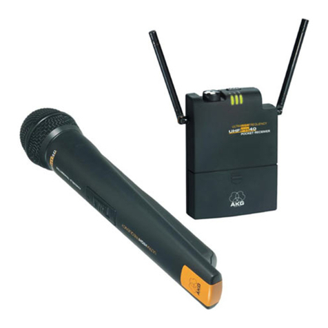
AKG PR 40 User manual

Bedienungshinweise . . . . . . . . . . . . . . . . . . . S. 2
Bitte vor Inbetriebnahme des Gerätes lesen!
User Instructions . . . . . . . . . . . . . . . . . . . . . p. 10
Please read the manual before using the equipment!
Mode d’emploi . . . . . . . . . . . . . . . . . . . . . . . p. 19
Veuillez lire cette notice avant d’utiliser le système!
Istruzioni per l’uso . . . . . . . . . . . . . . . . . . . . p. 27
Prima di utilizzare l’apparecchio, leggere il manuale!
Modo de empleo . . . . . . . . . . . . . . . . . . . . . p. 35
Antes de utilizar el equipo, sírvase leer el manual!
Instruções de uso . . . . . . . . . . . . . . . . . . . . p. 43
Favor leia este manual antes de usar o equipamen
to!
PR40 portablereceiver
WMS40
microtools
AKG.WIRELESS WIRELESS
MICROPHONE
SYSTEM

1 Sicherheit und
Umwelt
1.1 Sicherheit
1. Setzen Sie das Gerät nicht direkter
Sonneneinstrahlung, starker Staub-
und Feuchtigkeitseinwirkung, Regen,
Vibrationen oder Schlägen aus.
1.2 Umwelt
1. Entsorgen Sie verbrauchte Batterien
und Akkus immer gemäß den jeweils
geltenden Entsorgungsvorschriften.
Werfen Sie Batterien oder Akkus
weder ins Feuer (Explosionsgefahr)
noch in den Restmüll.
2. Wenn Sie das Gerät verschrotten,
entfernen Sie die Batterien bzw.
Akkus, trennen Sie Gehäuse,
Elektronik und Kabel und entsorgen
Sie alle Komponenten gemäß den
dafür geltenden Entsorgungs-
vorschriften.
2 Beschreibung
2.1 Einleitung
Vielen Dank, dass Sie sich für
ein Produkt aus dem Hause AKG ent-
schieden haben. Bitte lesen Sie die
Bedienungsanleitung aufmerksam
durch, bevor Sie das Gerät benützen,
und bewahren Sie die Bedienungs-
anleitung sorgfältig auf, damit Sie jeder-
zeit nachschlagen können. Wir wün-
schen Ihnen viel Spaß und Erfolg!
2.2 Lieferumfang
Kontrollieren Sie bitte, ob die
Verpackung alle oben ange-
führten Teile enthält. Falls
etwas fehlt, wenden Sie sich
bitte an Ihren AKG-Händler.
2.3 Empfohlenes Zubehör
• Ladestation CU 40
• Sonderausführungen ver-
schiedener AKG-Kopfhörer
mit 2,5 mm-Klinkenstecker
(auf Anfrage)
2.4 Beschreibung
Der PR 40 ist ein portabler Diversity-
Empfänger zur Verwendung mit allen
2
Empfänger
PR 40
1 Verbin-
dungskabel
mit freien
Enden
1 Gürtel-
spange
2 Batterien
1,5 V,
Größe AAA
Klett-
band

Sendern der Serie WMS 40 von AKG
(HT 40, PT 40, GB 40, MP 40, SO 40).
Mit dem mitgelieferten Klettband können
Sie den Empfänger an einem Mischpult,
Pedalboard (mehr Bewegungsfreiheit für
"effektvolle" Gitarristen mit GB 40) oder
einer Videokamera (für Reportage-
einsätze) befestigen.
Dank seiner kompakten Abmessungen
und der praktischen Gürtelspange eig-
net sich der PR 40 auch hervorragend
für Personenführungs- und kleinere
Dolmetschanlagen.
Eine fix eingestellte Rauschsperre
("Squelch") schaltet den Empfänger bei
zu schwachem Empfangssignal ab, so
dass die damit verbundenen Stör-
geräusche bzw. das Eigenrauschen des
Empfängers bei abgeschaltetem Sender
nicht hörbar werden.
Der PR 40 arbeitet auf einer fixen, quarz-
stabilisierten Empfangsfrequenz im UHF-
Bereich von 710 bis 865 MHz und ist mit
zwei drehbaren UHF-Antennen ausgestattet.
Die Farbe des Lautstärkereglers ent-
spricht der Empfangsfrequenz. Weitere
Informationen zur Empfangsfrequenz
finden Sie auch am Typenschild auf der
Geräterückseite.
2.5 Bedienelemente
2.5.1 Oberseite (siehe Abb. 1)
ON/OFF: Ein/Ausschalter
Ausgangsbuchse: Die 2,5 mm-
Stereo-Klinkenbuchse an der Ober-
seite des Empfängers bietet einen
Line-Ausgang mit fixem Pegel und
einen regelbaren Mono-Kopfhörer-
ausgang. Die Lautstärke des Kopf-
hörerausgangs können Sie mit dem
Lautstärkeregler (3) einstellen.
Die Ausgangsbuchse ist wie folgt
beschaltet:
Spitze: Line-Ausgang (fixer Pegel)
Ring: Kopfhörerausgang (regelbar)
Schaft: Masse
3
Abb. 1: Bedienelemente (Oberseite)

Wichtig: Um den Kopfhörerverstärker
nicht zu überlasten, schließen sie
an den Kopfhörerausgang nur
Kopfhörer mit einer Impedanz von
mindestens 16 Ωan.
Lautstärkeregler: Stellt die Laut-
stärke des Kopfhörerausgangs (2)
ein.
Die Farbe des Lautstärkereglers zeigt
die Empfangsfrequenz an.
RF-LED: Zeigt die Feldstärke des
Empfangssignals an.
LED leuchtet grün: optimale
Feldstärke.
LED leuchtet rot: Feldstärke = 0
(Sender ist ausgeschaltet oder
Empfänger auf einen anderen Kanal
als der Sender eingestellt) oder das
Empfangssignal ist stummgeschaltet,
weil der Squelch aktiv ist.
LED leuchtet nicht: Empfänger aus-
geschaltet, keine Batterien eingelegt
oder Batterien erschöpft.
AF-LED: Zeigt den empfangenen
Audiopegel an:
LED leuchtet grün und flackert an
den lautesten Stellen rot: optimaler
Audiopegel.
LED leuchtet rot: Übersteuerung.
LED leuchtet nicht: zu geringer
Audiopegel.
BATT: Diese LED zeigt den Lade-
zustand der Batterien an:
LED leuchtet grün: Batterien in
Ordnung.
LED leuchtet beim Einschalten
nicht auf: keine oder erschöpfte
Batterien eingelegt.
LED leuchtet rot: Batterien in ca.
60 Minuten erschöpft.
Antennen: Als Diversity-Empfänger
arbeitet der PR 40 mit zwei
Antennen, um das Sendersignal an
zwei verschiedenen Punkten emp-
fangen zu können. Die Diversity-
Elektronik aktiviert automatisch
immer jene Antenne, die das bessere
Signal liefert.
Batteriefach für die beiden mitgelie-
ferten 1,5 V-Batterien oder Akkus
derselben Größe (nicht mitgeliefert).
2.5.2 Rückseite (siehe Abb. 2)
Typenschild mit Zulassungssymbolen
und Frequenzinformationen
Gürtelspange zum Befestigen des
Empfängers am Gürtel.
2.5.3 Unterseite (siehe Abb. 2)
Ladekontakte zum Aufladen von
Akkus im Batteriefach mit Hilfe der
optionalen Ladestation CU 40.
4

3 Inbetriebnahme
3.1 Stromversorgung
Sie können den portablen Empfänger
PR 40 entweder mit den mitgelieferten
1,5 V-Batterien der Größe AAA oder
1,5 V-Akkus Größe AAA (nicht mitgelie-
fert) betreiben.
3.1 Batterien oder Akkus einlegen/
austauschen und testen (Abb. 3)
1. Drücken Sie den Schnapphaken am
Batteriefachdeckel (1) nach unten.
2. Ziehen Sie den Batteriefachdeckel (1)
nach unten vom Empfänger ab.
5
Abb. 2: Unterseite und Rückseite Abb. 3: Batterien einlegen

Wichtig: Der Schaumstoffpolster an
der Innenseite des Batteriefach-
deckels (1) fixiert die Batterien in
ihrer Position. Entfernen Sie den
Schaumstoffpolster nicht, da die
Batterien ansonsten nicht richtig
im Batteriefach fixiert sind und
Klappergeräusche verursachen
können.
3. Wenn sich leere oder defekte
Batterien im Batteriefach befinden,
nehmen Sie diese heraus.
4. Legen Sie die mitgelieferten bzw.
neue Batterien (2) wie in Abb. 3
gezeigt in das Batteriefach ein.
5. Stellen Sie den ON/OFF-Schalter (3)
auf ON.
Wenn die Batterien in gutem Zustand
sind, leuchtet die BATT-LED (4) grün.
Wenn die BATT-LED (4) rot zu leuch-
ten beginnt, sind die Batterien in ca.
60 Minuten erschöpft. Tauschen Sie
die Batterien möglichst bald gegen
frische aus.
Wenn die BATT-LED (4) nicht auf-
leuchtet, sind die Batterien erschöpft.
Legen Sie neue Batterien ein.
6. Schieben Sie den Batteriefachdeckel
(1) gegen die Pfeilrichtung auf den
Empfänger, bis der Batteriefach-
deckel (1) einrastet.
3.2 Betrieb mit Akkus (siehe Abb. 4)
Sie können den Empfänger anstelle nor-
maler Batterien auch mit zwei 1,5 V-
Akkus Größe AAA betreiben.
Wir empfehlen NiMH-Akkus des Typs
SANYO HR-4U (650 mAh) oder
Panasonic Rechargeable PRO+
(550 mAh).
Zum Aufladen der Akkus brauchen Sie
nur den Empfänger (1) wie in Abb. 4
gezeigt in die optionale Ladestation
CU 40 (2) zu stellen.
Wichtig: Bevor Sie den Empfänger in
die Ladestation stellen, schalten
Sie den Empfänger aus und klap-
pen Sie die Antennen ganz an die
Seitenwände des Empfängers her-
unter. Damit ist der Empfänger
leichter im Ladefach zu zentrieren
und Sie können die Ladestation
nicht mehr so leicht umstoßen wie
mit aufgestellten Antennen.
6
Abb. 4: Akkus aufladen mit optionaler
Ladestation CU 40

Nähere Hinweise zum Laden von Akkus
finden Sie in der Bedienungsanleitung
der Ladestation CU 40.
4 Anwendung
4.1 Montage an einem
Mischpult, einem Pedalboard
oder einer Videokamera
1. Drücken Sie die Enden der Gürtel-
spange wie in Abb. 5 gezeigt nach
innen und nehmen Sie die Gürtel-
spange heraus.
2. Schneiden Sie vom mitgelieferten
Klettband zwei Stücke ab, deren
Länge der Breite des Empfängers
entspricht.
3. Ziehen Sie die Schutzfolie von der
Rückseite des einen Stücks ab und
kleben Sie es auf die Rückseite des
Empfängers.
4. Kleben Sie das zweite Stück des
Klettbandes auf das Mischpult,
Pedalboard bzw. auf die Kamera.
Um einwandfreien Empfang zu
ermöglichen, positionieren Sie das
Klettband so, dass die Antennen des
Empfängers über das Mischpult,
Pedalboard bzw. die Kamera hinaus-
ragen (siehe Abb. 6).
4.1.1 Audio-Anschluss (siehe Abb. 7)
Das mitgelieferte Verbindungskabel
erlaubt Ihnen, den Line-Ausgang des
Empfängers mit einem Audioeingang an
einem Mischpult, Pedalboard oder
Camcorder zu verbinden.
1. Stellen Sie fest, welchen Steckertyp
Sie benötigen und löten Sie den
Stecker an das Verbindungskabel an.
Farbcode des Verbindungskabels:
Rote Ader: Line-Pegel
Weiße Ader: Kopfhörersignal
Abschirmung: Masse
7
Abb. 6: Optimale Antennenposition
Abb. 5: Gürtelspange abnehmen

Wichtig: Lesen Sie bitte in der
Bedienungsanleitung des Gerätes,
an das Sie den Empfänger ansch-
ließen möchten, nach, welche Ader
Sie an welchen Stift anschließen
müssen.
2. Wenn der gewählte Eingang mit
Phantomspeisung ausgestattet ist,
schalten Sie die Phantomspeisung ab.
Lesen sie dazu in der Bedienungs-
anleitung des Mischpults oder
Camcorders nach.
3. Stecken Sie den 2,5-mm-Klinken-
stecker (1) des Verbindungskabels an
die Ausgangsbuchse (2) des
Empfängers an.
Der 2,5-mm-Klinkenstecker ist dreh-
bar mit dem Kabel verbunden.
Dadurch können Sie das Kabel eng
am Empfänger anliegen lassen.
4. Stecken Sie den anderen Stecker (3)
des Verbindungskabels an die
gewünschte Eingangsbuchse (4) an.
4.2 Personenführungs- und
Dolmetschanlagen
Für diese Anwendungen können Sie bei
Ihrer lokalen AKG-Vertretung den
gewünschten AKG-Kopfhörer in einer
Sondervariante mit 2,5 mm-Stereo-
klinkenstecker bestellen.
Wichtig: Schließen Sie an den
Empfänger PR 40 nur Kopfhörer
mit einer Impedanz von minde-
stens 16 Ωan, da Kopfhörer mit
geringerer Impedanz die Aus-
gangsstufe des Empfängers über-
lasten würden.
8
Abb. 7: Audio-Anschluss Abb. 8: Kopfhörer anschließen
AB
,

1. Zur Entlastung der Steckverbindung
vom Zug des Kopfhörerkabels führen
Sie das Kopfhörerkabel unter der
Gürtelspange durch (siehe Abb. 8).
2. Stecken Sie den 2,5-mm-Klinken-
stecker (1) des Kopfhörerkabels an
die Ausgangsbuchse (2) des
Empfängers an.
3. Stellen Sie mit dem Lautstärkeregler
(3) die Lautstärke des Kopfhörers ein.
4.3 Antennen ausrichten (Abb. 9)
Optimale
Empfangssicherheit
erreichen Sie, in-
dem Sie beide
Antennen in einem
Winkel von je 45°
vom Empfänger
weg zeigen lassen.
Wenn Sie die
Antennen so aus-
richten, arbeitet die
Diversity-Funktion optimal und verhin-
dert Empfangsstörungen wie Rauschen
oder Dropouts am wirkungsvollsten.
Wenn Sie den Empfänger am Gürtel tra-
gen, spielt es keine Rolle, ob sie die
Antennen nach oben oder nach unten
zeigen lassen, vorausgesetzt, sie sind
wie oben beschrieben "V-förmig" ausge-
richtet.
Wenn Sie den Empfänger an einem
Camcorder befestigen, richten Sie die
Antennen genauso aus und achten Sie
darauf, dass die Antennen über das
Kameragehäuse hinausragen. Auf diese
Weise kann es zu keinen Dropouts infol-
ge von Abschattung der Antennen durch
das Kameragehäuse kommen.
5 Reinigung
Reinigen Sie das Gehäuse des
Empfängers mit einem mit
Wasser befeuchteten Tuch.
6 Technische Daten
Empfangsfrequenz: 710 - 865 MHz
Modulationsart: FM
Audioübertragungsbandbreite: 40 – 20.000 Hz
Klirrfaktor: <0,8 %
Signal / Rauschabstand: typ. 108 dB(A)
Stromaufnahme: typ. 120 mA
Betriebsdauer: >6 h mit 2 x 1,5 V-
Batterien Typ AAA
Audio-Ausgänge: Line, asymmetrisch
(Spitze): -6dBm (10 kΩ),
Kopfhörerausgang
(Ring): typ.
18 mW (15 Ω)
;
typ. 13 mW (100 Ω)
Abmessungen: 77 x 55 x 15 mm
Gewicht: ca. 60 g
Dieses Produkt entspricht den Normen
EN60065:1998, EN301 489-9 v.1.1.1
(09-2000) und EN300 422-2 v.1.1.1
(07-2000).
9
Abb. 9: Antennen-
ausrichtung

1 Safety and
Environment
1.1 Safety
1. Do not expose the equipment to
direct sunlight, excessive dust, moi-
sture, rain, mechanical vibrations, or
shock.
1.2 Environment
1. The AC adapter will draw a small
amount of current even when the
equipment is switched off. To save
energy, disconnect the AC adapter
from the power outlet if you will leave
the equipment unused for a long peri-
od of time.
2. When scrapping the equipment,
separate the case, circuit boards,
and cables, and dispose of all com-
ponents in accordance with local
waste disposal rules.
10
FCC Statement
This equipment has been tested and
found to comply with the limits for a Class
B digital device, pursuant to Parts 74, 15,
and 90 of the FCC Rules. These limits are
designed to provide reasonable protec-
tion against harmful interference in a resi-
dential installation. This equipment gene-
rates, uses, and can radiate radio fre-
quency energy and, if not installed and
used in accordance with the instructions,
may cause harmful interference to radio
communications. However, there is no
guarantee that interference will not occur
in a particular installation. If this equip-
ment does cause harmful interference to
radio or television reception, which can
be determined by turning the equipment
off and on, the user is encouraged to try
to correct the interference by one or more
of the following measures:
• Reorient or relocate the receiving
antenna.
• Increase the separation between the
equipment and the receiver.
• Connect the equipment into an outlet
on a circuit different from that to which
the receiver is connected.
• Consult the dealer or an experienced
radio/TV technician for help.
Shielded cables and I/O cords must be
used for this equipment to comply with
the relevant FCC regulations.
Changes or modifications not expressly
approved in writing by AKG Acoustics
may void the user’s authority to operate
this equipment.
This device complies with Part 15 of the
FCC Rules. Operation is subject to the
following two conditions: (1) this device
may not cause harmful interference, and
(2) this device must accept any interfe-
rence received, including interference
that may cause undesired operation.
2 Description
2.1 Introduction
Thank you for purchasing an
AKG product. This Manual contains
important instructions for setting up and
operating your equipment. Please take a
few minutes to read the instructions
below carefully before operating the
equipment. Please keep the Manual for
future reference. Have fun and impress
your audience!
2.2 Unpacking
Check that the packaging
contains all of the com-
ponents listed above. Should
anything be missing, please
contact your AKG dealer.
2.3 Optional Accessories
• CU 40 charger
• Custom versions of AKG
headphones with .1-in. jack
plug. (On request – K 10
shown.)
2.4 Description
The PR 40 is a portable diversity receiver
for use with all AKG WMS 40 Series
transmitters (HT 40, PT 40, GB 40, MP
40, SO 40). The supplied Velcro strip
allows you to mount the receiver on a
mixer, pedalboard (to give effect-loving
guitarists more room to move), or a
video camera for ENG use.
Thanks to its compact dimensions and
convenient belt clip, the PR 40 is an
excellent receiver for tour guide and
small interpretation systems.
A preset squelch will mute the receiver if
the received signal is too weak so the
related noise or the self-noise of the
receiver will not become audible when
the transmitter is switched OFF.
The PR 40 operates on one fixed, quartz
stabilized frequency in the 710 MHz to
865 MHz UHF carrier frequency range
and uses two folding UHF antennas. The
color of the volume control indicates the
receiving frequency. The type plate on
the receiver rear panel provides detailed
frequency information.
11
PR 40
receiver
1 connecting
cable with
unterminated
leads
1 belt
clip
2 AAA
size 1.5 V
batteries
Velcro
strip

2.5 Controls
2.5.1 Top Panel (Fig. 1)
ON/OFF: On/off switch.
Output jack: This .1-in. TRS jack on
the receiver top panel provides a
fixed-level line output and an adjusta-
ble mono headphone output. The
volume control (3) lets you adjust the
volume level of the headphone out-
put.
The output jack is wired as follows:
Tip: line output (fixed level)
Ring: headphone output (adjustable)
Sleeve: ground
Important: To avoid overloading the
headphone amplifier, do not con-
nect headphones with an imped-
ance lower than 16 Ωto the head-
phone output.
Volume control: Sets the volume
level of the headphone output (2).
The color of the volume control knob
indicates the receiving frequency of
your receiver.
RF LED: Indicates the field strength
of the received signal:
LED lighting green: optimum field
strength.
LED lighting red: field strength is
zero (the transmitter is OFF or the
receiver has been set to a different
channel than the transmitter) or the
received signal is muted because the
squelch is engaged.
LED does not light: power to the
receiver is OFF, no batteries are in the
battery compartment, or the batteries
are dead.
AF LED: Indicates the received audio
level:
LED lighting green and flashing red
on peaks: optimum audio level.
12
Fig. 1: Top panel controls.

LED lighting red: audio section is
overloaded.
LED does not light: audio level is too
low.
BATT: Indicates battery status:
LED lights green: batteries are O.K.
LED does not illuminate on switch-
ing the power ON: no or dead batte-
ries in the battery compartment.
LED lights red: batteries will be dead
in about 60 minutes.
Antennas: Being a diversity receiver,
the PR 40 uses two antennas to
receive the transmitter signals at two
different spots. The diversity circuit
will automatically activate the anten-
na that provides the better signal.
Battery compartment: Accepts the
supplied 1.5 V dry batteries or
rechargeable batteries of the same
size (not supplied).
2.5.2 Rear Panel (Fig. 2)
Type plate with approval marks and
frequency information (frequencies,
frequency sets, color code).
Belt clip for fixing the receiver on
your belt.
2.5.3 Bottom Panel (Fig. 2)
Charging contacts for charging
rechargeable batteries inside the bat-
tery compartment using the optional
CU 40 charger.
13
Fig. 2: Bottom and rear panels.

3 Setting Up
3.1 Powering
To power the PR 40 portable
receiver you can use the supplied 1.5 V
AAA size dry batteries or 1.5 V AAA size
rechargeable batteries (not supplied).
3.2 Inserting/Replacing and Testing
Batteries (Fig. 3)
1. Depress the snap hook on the battery
compartment lid (1).
2. Pull the battery compartment lid (1)
down to remove it from the receiver.
Important: The foam pad on the inside
of the battery compartment lid (1)
holds the batteries in place. Do not
remove the foam pad. If you do, the
batteries will not be held in place
securely and may cause a rattling
noise.
3. If there are dead or defective batte-
ries inside the battery compartment,
remove the batteries.
4. Insert the supplied or new batteries
(2) into the battery compartment as
shown in fig. 3.
5. Set the ON/ OFF switch (3) to ON.
If the batteries are in good condition,
the BATT LED (4) will light green. If
the BATT LED (4) illuminates red, the
batteries will be dead within about 60
minutes. Replace the batteries with
new ones as soon as possible.
If the BATT LED (4) fails to illuminate
the batteries are dead. Insert new
batteries.
6. Slide the battery compartment lid (1)
onto the receiver against the direc-
tion of the arrow to the point that the
lid (1) will click shut.
14
Fig. 3: Inserting batteries.

3.3 Using Rechargeable Batteries
(Fig. 4)
Instead of dry batteries, you can also
use two 1.5 V rechargeable batteries to
power the receiver. We recommend
SANYO HR-4U (650 mAh) or Panasonic
Rechargeable PRO+ (550 mAh) NiMH
rechargeable batteries.
To charge the batteries, insert the receiv-
er (1) into the optional CU 40 charger (2)
as shown in fig. 4.
Important: Before placing the receiver
in the charger, switch the receiver
OFF and fold the antennas all the
way down, against the side panels
of the receiver. With the antennas
folded down, it will be easier to
center the receiver inside the char-
ging compartment and the charger
will be less prone to be knocked
over.
For details on charging batteries, refer to
the CU 40 charger manual.
4 Applications
4.1 Mounting the Receiver
on a Mixer, Pedalboard, or
Video Camera
1. Press the ends of the belt clip inward
as shown in fig. 5 and remove the
belt clip.
2. Cut two 2-inch lengths off the sup-
plied Velcro strip.
3. Remove the backing from one of the
15
Fig. 4: Using the optional CU 40 charger.
Fig. 5: Removing the belt clip.

strips and attach it to the receiver
rear panel.
4. Remove the backing from the other
strip and attach it to the mixer, pedal-
board, or camera.
To ensure perfect reception, position
the Velcro strip so that the antennas
on the receiver will protrude above
the mixer, pedalboard, or camera.
(Refer to fig. 6).
4.1.1 Audio Connection (Fig. 7)
The supplied connecting cable lets you
connect the line output on the receiver
to an audio input on a mixing console,
pedalboard, or video camera.
1. Check what connector type you will
need for your equipment and solder
the connector to the cable.
Cable pinout:
Red wire: line level
White wire: headphone signal
Shield: ground
Important: Please refer to the instruc-
tion manual of the equipment to
which you will connect the receiver
to check which wire you should
connect to which pin on the
connector.
2. If the selected input provides phan-
tom power, switch the phantom
power OFF.
Refer to the manual of your equip-
ment.
3. Plug the .1-in. jack plug (1) on the
connecting cable into the output jack
(2) on the receiver.
16
Fig. 6: Optimum antenna position.
Fig. 7: Audio connection
AB
,

The connecting cable has a rotatable
.1-in. jack plug so you can route the
cable to rest snugly against the recei-
ver.
4. Plug the other connector (3) on the
connecting cable into the desired
input jack (4).
4.2 Tour Guide and Interpretation
Systems
Contact your local AKG Distributor to
order your preferred AKG headphones in
a custom version with a 0.1-in. TRS jack
plug.
Important: Do not connect head-
phones with an impedance of less
than 16 Ωto the PR 40 receiver.
Headphones with a lower im-
pedance would overload the
receiver output stage.
1. To relieve the connection of the strain
of the headphone cable, pass the
headphone cable under the belt clip
as shown in fig. 8 (left).
2. Plug the .1-in. jack plug (1) on the
headphone cable into the output jack
(2) on the receiver.
3. Use the volume control (3) to set the
desired volume level for the head-
phones.
4.3 Aligning the Antennas (Fig. 9)
For optimum recep-
tion, point each
antenna away from
the receiver at an
angle of 45 de-
grees. With the
antennas aligned
like this, the diversi-
ty function will
operate optimally
and prevent dis-
turbances such as
noise or dropouts most efficiently.
If you wear the receiver on the belt it
makes no difference whether you point
the antennas up or down as long as you
align them in a "V" as described above.
If you mount the receiver on a mixer or
other equipment, align the antennas in a
"V" and make sure the antennas will
17
Fig. 8: connecting headphones.
Fig. 9: Optimum
antenna alignment

protrude above the equipment case.
This will prevent dropouts due to
shadow effects of the case.
5 Cleaning
To clean the transmitter case,
use a soft cloth moistened with
water.
6 Specifications
Receiving frequency range: 710 to
865 MHz
Modulation: FM
Audio bandwidth: 40 to 20,000 Hz
T.H.D.: <0.8%
Signal/noise ratio: 108 dB(A) typ.
Current consumption: 120 mA typ.
Battery life: >6 hours (2 x 1.5 V
AAA size batteries)
Audio outputs: Unbal. line (tip): -6
dBm (10 kΩ)
Headphone output
(ring): 18 mW typ. into
15 Ω; 13 mW typ. into
100 Ω
Size: 77 x 55 x 15 mm
(3 x 2.2 x 0.6 in.)
Weight: approx. 60 g (2.1 oz.)
This product complies with the following
standards: EN60065:1998, EN301 489-9
v.1.1.1 (09-2000) and EN300 422-2 v.1.1.1
(07-2000).
18

1 Sécurité et
environnement
1.1 Sécurité
1. N’exposez jamais l’appareil directe-
ment aux rayons du soleil, à une
atmosphère poussiéreuse, à la pluie,
aux vibrations ou aux chocs.
1.2 Environnement
1. Pour l’élimination des piles ou des
accus usés conformez-vous toujours
aux règlements en vigueur. Ne jetez
jamais des piles ou des accus au feu
(risque d’explosion) ni avec les
déchets ordinaires.
2. Si vous devez mettre l’appareil au
rebut, enlevez les piles ou les accus,
séparez l’électronique, les câbles et
le boiter et conformez-vous aux
règlements en vigueur pour l’élimina-
tion des différents composants.
2 Description
2.1 Introduction
Nous vous félicitons d’avoir
choisi un produit AKG. Lisez attentive-
ment la présente notice avant d’utiliser
l’appareil et conservez-la soigneuse-
ment pour l’avoir sous la main lorsque
vous aurez besoin de la consulter. Nous
espérons que vous aurez du plaisir à uti-
liser cet appareil et vous souhaitons
beaucoup de succès !
2.2 Fournitures d’origine
Vérifiez si toutes les pièces
énumérées ci-dessus se
trouvent bien dans l’emballa-
ge. Si ce n’est pas le cas,
veuillez le signaler à votre
fournisseur AKG.
2.3 Accessoires recommandés
• Chargeur CU 40
• Différents casques AKG en
exécution spéciale avec
fiche jack de 2,5 mm (sur
demande)
2.4 Description
Le PR 40 est un récepteur Diversity por-
table s’utilisant avec tous les émetteurs
19
Récepteur
PR 40
1 câble de
raccorde-
ment à
extrémités
libres
1 clip de
ceinture
2 piles de
1,5 V,
dimension
AAA
Bande
auto-
agrip-
pante

de la gamme WMS 40 d’AKG (HT 40, PT
40, GB 40, MP 40, SO 40). La bande
autoagrippante fournie permet de fixer le
récepteur sur un pupitre de mixage, un
clavier à pédale (pour laisser une plus
grande liberté de mouvements aux gui-
taristes recherchant les effets et utilisant
un GB 40) ou une caméra vidéo (pour les
reportages).
Grâce à ses dimensions compactes et
au clip de ceinture pratique, le PR 40
convient aussi parfaitement pour les
systèmes de guides audio et les petits
équipements de traduction simultanée.
Un silencieux (squelch) à réglage fixe
coupe le récepteur lorsque le signal reçu
est trop faible, afin de rendre inaudibles
les bruits parasites qui en résultent ou le
bruit propre du récepteur lorsque l’émet-
teur est coupé.
Le PR 40 fonctionne sur une fréquence
porteuse fixe stabilisée par cristal sur la
plage de porteuses UHF de 710 MHz à
865 MHz ; il est équipé de deux anten-
nes UHF orientables.
La couleur du bouton de réglage de
volume correspond à la fréquence de
réception. Vous trouverez les informati-
ons nécessaires sur la fréquence de
réception sur la plaque d’identité au dos
de l’appareil.
2.5 Eléments de commande
2.5.1 Face supérieure (voir Fig. 1)
ON/OFF : Interrupteur marche-arrêt
Sortie audio : La prise jack stéréo de
2,5 mm sur la face supérieure du
récepteur a une sortie LINE à niveau
fixe et une sortie casque mono régla-
ble. Le volume du casque se règle à
l’aide du bouton de réglage de volu-
me (3).
Brochage de la prise de sortie :
Pointe : sortie ligne (niveau fixe)
Anneau : sortie casque (réglable)
Tige : masse
20
Fig. 1: Eléments de commande (face supérieure)
Other manuals for PR 40
1
Table of contents
Languages:
Other AKG Receiver manuals