Akw Arka 25421-2 User manual

Arka Thermostatic
TMV3 Mixer Shower
INSTALLATION INSTRUCTIONS
Please read all instructions before installation and leave this document
with the end user for future reference as it contains important warranty information
Stock Code
25421-2

General: 01905 823 298 | www.akw-ltd.co.uk2
2
COMPONENTS & DIMENSIONS
Components & Dimensions
Components
Dimensions
1/2” BSP Fitting
3/4” BSP Fitting
Inlet Cover
Flow Lever
Temperature Lever
Filter
Hot Inlet
Cold Inlet
Shower Outlet
Please check that all components are present from the
packaging box prior to installation of this product. If anything
is missing or damaged please contact General Enquiries - see
back page.
286 mm
150 15 mm
48 mm
76 mm
20 mm
47
41 mm
G 1/2”
60 mm
151 mm
55 mm
76 mm
G 1/2”
286 mm
150 15 mm
48 mm
76 mm
20 mm
47
41 mm
G 1/2”
60 mm
151 mm
55 mm
76 mm
G 1/2”

Technical Support: 01905 560 219 3Order: 01905 823 299 |orders.akw-ltd.co.uk
3
SPECIFICATIONS
Specications
Minimum Dynamic Pressure 0.2 Bar
Maximum Dynamic Pressure 5 Bar
Maximum Static Pressure 10 Bar
Dimensions for Fitting 150 mm, +/-15 mm
Concealed & Exposed Water Entry Back
Inlet Connectors 3/4” - 1/2” BSP
Valve Type Thermostatic Bar Shower Mixer with
Independent Flow & Temperature Control
Approvals TMV3, WRAS
Maximum Pre-Set Temperature 38 oC
Maximum Pressure Difference
(Between Hot & Cold Water Supply) 1 Bar
Maximum Flow (@ 3 Bar) 20 L/Min
Do not choose a position where the shower could become frozen. Do not connect this mixer
shower to any form of tap or fitting not recommended by the manufacturer. Do not allow the
inlet pressure or flow rates to operate outside the guidelines laid out in ‘site requirements’.
This product is precision-engineered and should give continued superior and safe performance,
provided that:
1. It’s installed, commissioned, operated and maintained in accordance with the
recommendations given in this manual and must be conducted by designated, qualied and
competent personnel.
2. Installation must comply with all local/national water supply authority regulations/by-laws
and building and plumbing regulations.
3. Periodic attention is given, as necessary, to maintain the product in good functional order.
This product is designed to deliver water consistently at a safe temperature. In keeping
with every other mechanism, the Vettora mixer cannot be considered as being functionally
infallible therefore the Vettora mixer cannot totally replace the vigilance of nursing/
supervisory staff where that is necessary.
Provided it is installed, commissioned, operated and maintained within these
recommendations, the risk of failure is not eliminated but can be reduced to a minimum.

General: 01905 823 298 | www.akw-ltd.co.uk4
4
INSTALLATION
Installation
Seal with PTFE tape
or liquid sealant
150 ± 15 mmHot
Cold
Filter
150 ± 15 mmHot
Cold
Filter
150 ± 15 mmHot
Cold
Filter
150 ± 15 mmHot
Cold
Filter
All pipe work must be flushed out and routed as protruding before installing the shower mixer.
The hot and cold supply pipes must be anchored rigidly and must be mounted to a solid wall
type to support the valve and stop any movement after installation. The inlet centres on the
shower valves are 150mm. Minimise pipework wherever possible. Recommended minimum
supply line pipe diameter is 1/2” or 15mm.
If it is intended to operate the shower in areas of hard water (above 200-ppm temporary
hardness), a scale inhibitor may have to be tted. For best performance the shower-handset
MUST be regularly cleaned to remove scale and debris.
1. Mark out and drill two holes 150 ± 15 mm away from each other for the inlet pipes to feed
through. Make sure that the holes are levelled.
2. The inlet threaded connection should be made only with a PTFE tape or liquid sealant.
Do not use oil-based, non-setting jointing compounds.
3. Assemble the inlet cover, lter and 1/2” - 3/4” BSP tting, and check valve (remove with a 9 mm
hex key) and then nally the bar mixer itself.
4. Clean with a cloth and warm soapy water when everything is secure.

Technical Support: 01905 560 219 5Order: 01905 823 299 |orders.akw-ltd.co.uk
5
OPERATION
Operation
The maximum temperature is factory pre-set to approximately 41 °C under ideal installation
conditions at the factory.
To check or change this setting, refer to Adjust temperature setting information given on page
8 in section: “Commissioning”.
Adjusting the Temperature
The temperature is controlled by rotating the temperature lever on the right side of the mixer.
The temperature is limited to a comfortable showering level of 38 °C. To obtain a higher
temperature, press the override button on the temperature lever and continue to rotate the
lever. The maximum override temperature must be set to 41 °C.
Adjusting the Flow
The ow is controlled by rotating the ow lever on the left side of the mixer.
For water economy reasons, the ow is limited by a stop. To obtain a higher ow, press the
override button on the ow lever and continue to rotate the lever.
Flow Lever
Temperature Lever
On/Increase/Decrease Temperature
On/Increase/
Decrease
Flow
Override Buttons

General: 01905 823 298 | www.akw-ltd.co.uk6
6
COMMISSIONING
Commissioning
Application Abbreviated Designation Mixed Water Temperature (°C)
Shower -HP-S, LP-SE 41 Maximum
Purpose
Since the installed supply conditions are likely to be different from those applied in the
laboratory tests, it is appropriate, to carry some simple checks and tests out on each mixing
valve at commissioning to provide a performance reference point for future in-service tests.
Procedure
Check that:
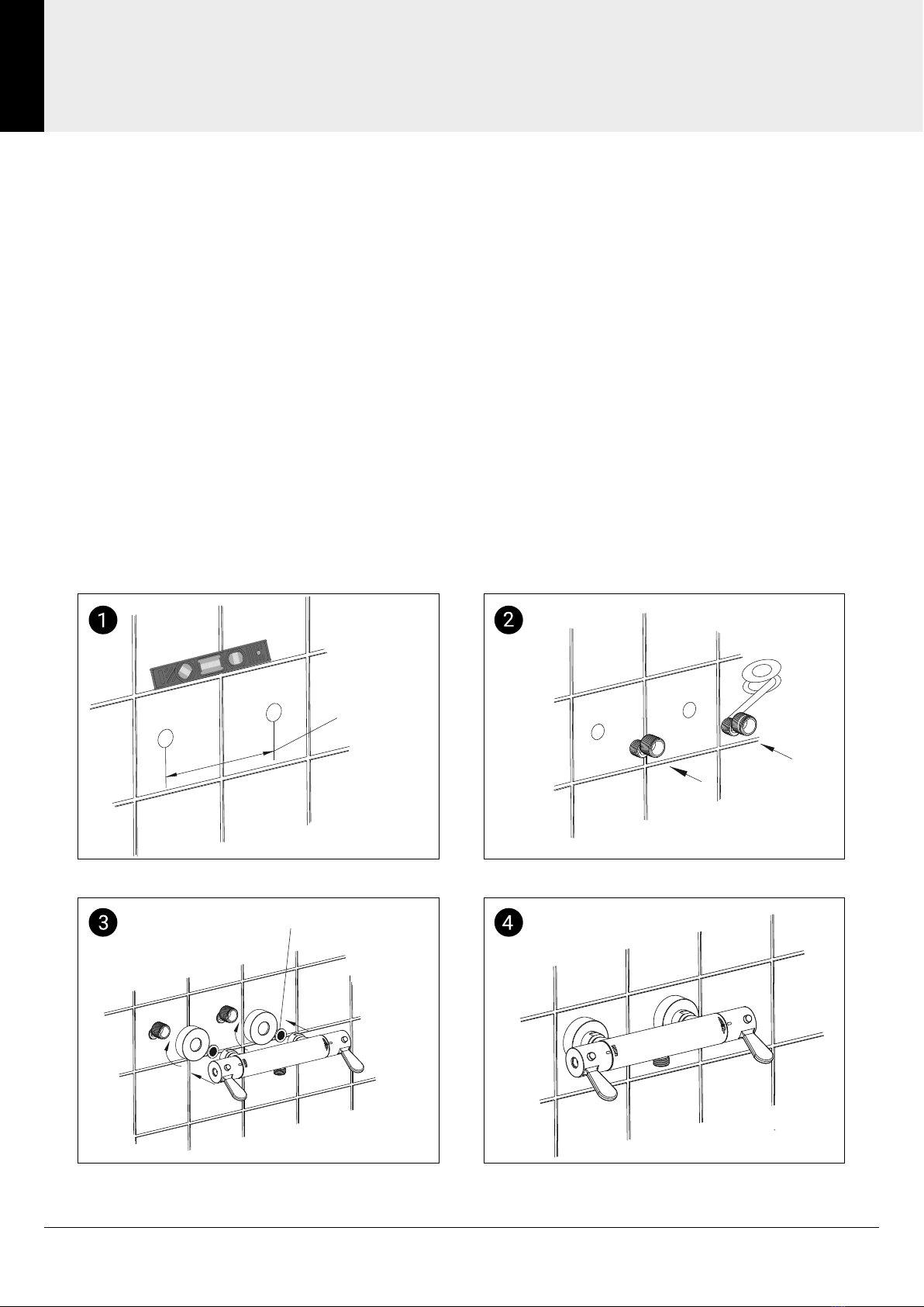
a. The designation of the SMV-001 mixing valve matches the intended application.
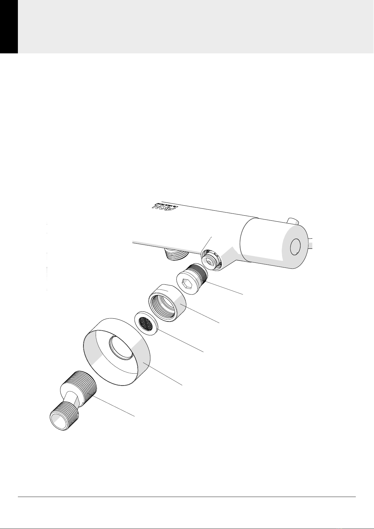
b. The supply pressures are balanced and within the range of operating pressures for the
designation of the valve.
c. The supply temperatures are within the range permitted for the valve.
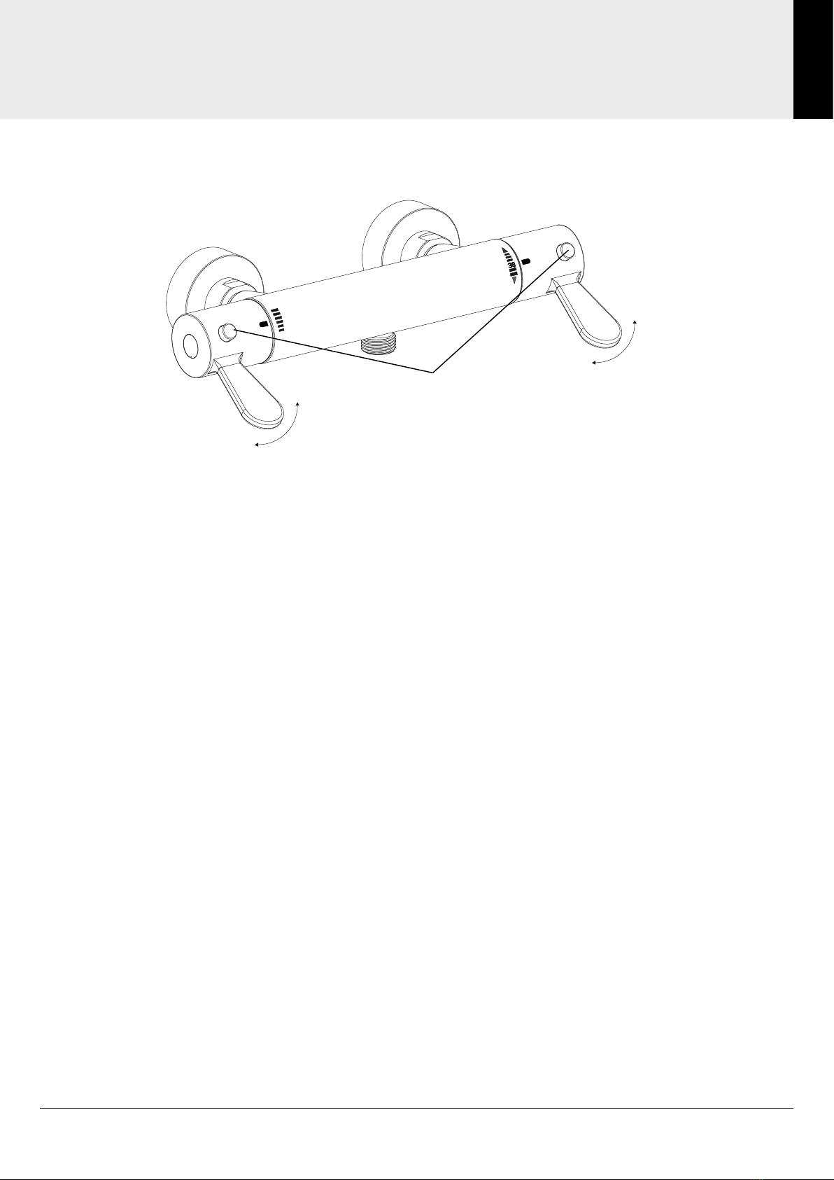
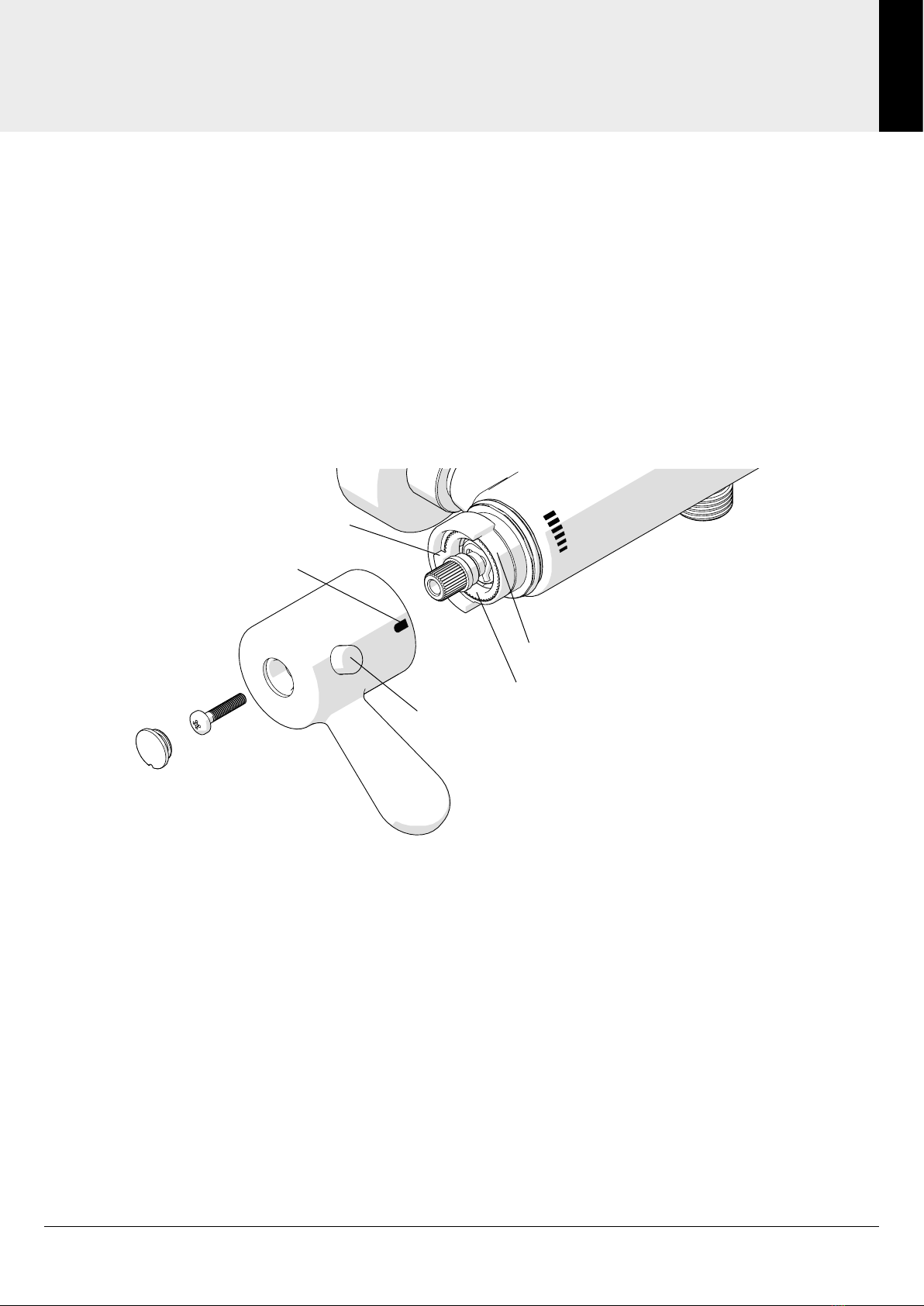
To adjust the temperature of the mixed water see page 8 and then carry the following
sequence out:
a. Record the temperature of the hot and cold water supplies (see page 13).
b. Record the temperature of the mixed water at the largest draw-off ow rate.
c. Record the temperature of the mixed water at a smaller draw-off ow rate.
d. Isolate the cold water supply to the mixing valve and monitor the mixed water temperature.
e. Record the maximum temperature achieved as a result of (d) and the nal stabilised temperature.
f. Record the equipment, thermometer etc. used for these measurements.
Maximum Temperature
The maximum blend temperature obtainable by the user should be limited to prevent
accidental selection of a temperature that is too hot.
The SMV-001 mixer valve is fully performance tested and the maximum override temperature
is pre-set to 41°C under ideal installation conditions at the factory. Site conditions and
personal preference may dictate that the maximum temperature be reset following
installation.
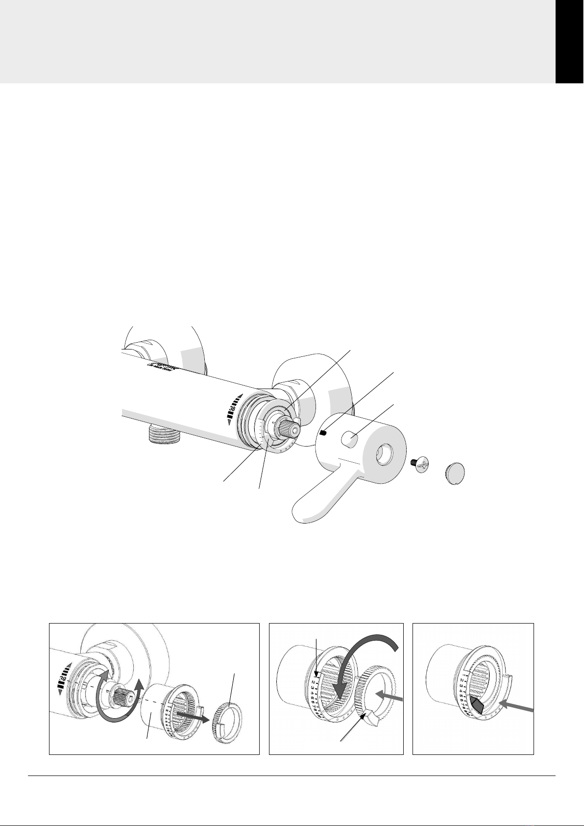
Maximum Temperature Setting
Make sure that an adequate supply of hot water is available at the hot inlet of the SMV-001
Mixer. The minimum temperature of the hot water must be at least 10°C above the desired
blend temperature. However, during resetting, this should be close to the typical storage
maximum to offset the possibility of any blend shift due to uctuating supply temperatures.
Make sure that both inlet isolating valves are fully open.
Temperatures should always be measured using a thermometer with proven accuracy.

Technical Support: 01905 560 219 7Order: 01905 823 299 |orders.akw-ltd.co.uk
7
COMMISSIONING
Commissioning
Step 1: Adjusting the temperature setting
For a TMV3 installation, the maximum blended temperature should be set to 41 °C.
For a non-TMV3 installation, the maximum blended temperature can be set to above 41 °C.
1. Turn the temperature lever to the 38 °C mark and test that the temperature of the water from
the shower outlet is 38 °C. If the water is not 38 °C, proceed with the following procedure.
2. Turn the temperature lever to the fully cold position.
3. Hold the temperature override button down and slowly turn the lever until the output water
reaches 38 °C.
4. Wait for the water temperature to stabilise. Turn the ow lever to the off position.
5. Without turning the temperature lever, unscrew the screw and remove the paddle lever.
6. Remove and rotate the Limit Ring until the 38 °C step is in line with the notch on the valve
and the 38 °C number mark on the shower mixer body.
Replace the lever with the temperature mark aligned with the 38°C position on the shower mixer.
7. Hold the temperature override button down and turn the lever to maximum temperature.
Measure the stabilised water temperature. If the temperature is not 41 °C, set the lever with
the temperature mark aligned back in the 38 °C position and remove the lever.
Remove and rotate the Override Limit Ring accordingly to the steps in the table below and
repeat this process until the maximum override temperature is set at 41 °C.
1
2
3
4
56
Temperature Mark
Override Button
Override Limit Ring
41 °C Step
Limit Ring
Temperature Lever
Step 3::See the arrow below, the step side of override limit ring to get align with the different
scales marked on limit ring. After that, push the override limit ring in place.
((Different scale reflects different temperature))
Step 2::Pull out the limit ring and override limit ring, get them apart.
Step 3::See the arrow below, the step side of override limit ring to get align with the different
scales marked on limit ring. After that, push the override limit ring in place.
((Different scale reflects different temperature))
Override
Limit Ring
41°C Step
Limit Ring
38°C Step

General: 01905 823 298 | www.akw-ltd.co.uk8
8
COMMISSIONING
Commissioning
Step No. Temperature °C
1 40
2 41
3 41
4 42
5 43
6 44
7 45
8 46
Note: for non-TMV3 applications, the Override Limit Ring may be adjusted beyond 41 °C.
8. Finally, replace the lever without turning it, in-line with the 38 °C mark and tighten the screw.
Test that the temperature of the water from the shower outlet is now set at 38 °C without
using the override button.
Test the maximum temperature by pressing the override button and turning the lever to
hottest position. This must be set to 41 °C. If the temperature is not 41 °C, re-adjust the
Override Limit Ring accordingly by removing the lever again. Only when then temperatures
are set, then replace the cover cap.
Override Limit Ring
Step
Limit Ring
1
2
3
4
56

Technical Support: 01905 560 219 9Order: 01905 823 299 |orders.akw-ltd.co.uk
9
COMMISSIONING
Commissioning
3. Remove the Flow Lever and adjust the Limit Ring so that it is aligned with the ow mark
position. This will set the maximum normal ow rate position before the override button
is depressed.
4. Replace the Flow Lever and turn the lever to the desired maximum override ow rate
position whilst holding down the Override Button. Record the ow mark position on the
shower mixer. Remove the Flow Lever and adjust the Override Limit Ring so that the step is
aligned with the ow mark position. This will set the maximum override ow rate position
when the override button is depressed.
5. Replace the Flow Lever without turning it so that the ow mark is aligned with the
maximum override mark position recorded on the shower mixer.
If the normal or maximum override ow rates are incorrect, then re-adjust accordingly.
Finally replace, tighten the screw, and replace cap.
Note: record the commissioning tests on page 13
Override Limit Ring
Step
Limit Ring
Override Button
Flow Lever
Flow Mark
Adjusting the ow rate setting
If the pre-set ow rate is not appropriate, you may choose to adjust it.
For example, you may choose to lower the ow rate to save water.
Both Normal and Maximum Override ow rate positions may be adjusted.
1. Turn the Flow Lever to the fully off position. Unscrew and remove the ow lever without
turning it. Replace the Flow Lever at the desired off position.
2. Hold the Override Button down and slowly turn the Lever until the output water reaches the
desired normal ow rate position. Record the ow mark position on the shower mixer.

General: 01905 823 298 | www.akw-ltd.co.uk10
10
MAINTENANCE & SERVICING
Maintenance & Servicing
SMV-001
Connections:
1. Turn the hot and cold water supplies off.
2. Disassemble the shower mixer, clean the lter thoroughly
3. After re-assembling the shower mixer, clean the surface with a cloth and warm soapy
water only.
Note:
Do not use scourers or abrasive cleaners which may affect the surface nish.
Never use corrosive acidic or alkaline cleaning materials on ttings or surfaces.
Always ush cleaning materials away with copious amounts of water and wipe down.
1/2” - 3/4” BSP Fitting
Inlet Cover
Filter
Inlet Connector
Check Valve
(Remove with 9 mm hex key)

Technical Support: 01905 560 219 11Order: 01905 823 299 |orders.akw-ltd.co.uk
11
IN-SERVICE TESTING & TROUBLESHOOTING
In-Service Testing & Troubleshooting
The purpose of in-service testing is to regularly monitor the thermal performance of the
SMV-001 mixer valve. Deterioration in performance can indicate the need for service work
to be carried out on the system.
At intervals of 6-8 weeks and 12-15 weeks after commissioning:
1. Check that supply parameters are still within the expected values and check system for faults.
2. Carry commissioning procedures out using the same test equipment. If the mixed water
temperature has changed by a signicant amount (more than 1 °C), ensure that the in line
lters are clean and that the check valves are working and all isolation valves are fully open.
If no fault can be found, check and record the mixed water temperatures and re-adjust the
mixed water temperature to the values in table 3. Complete the commissioning procedure. If
the mixed water temperature exceeds the values of the maximum recorded temperature by
more than 2 °C, the need for service work is indicated.
Depending on the results of these two tests, the following should be adopted:
a. If a small change (e.g. 1 °C to 2 °C) occurs in one of these tests or there is no signicant change
(e.g. 1 °C maximum), the next service test should be 24-28 weeks after commissioning.
b. If small changes occur in both tests or a larger change occurs in one test (exceeding 2 °C),
the next service test should be carried out 18 to 21 weeks after commissioning.
Fault Diagnosis
Water temperature
is too hot or cold
No hot water reaching the SMV-001 check supply.
Inlet tails are reversed - Check connections.
Filters are blocked - Check lters
Conditions are outside of the specications.
Isolation valve is closed - Check valves.
Temperature set too high during commissioning - Check setting.
Airlock in the inlet pipework - check for airlocks.
Water supply is unbalanced - check that the supply pressure is balanced
Low Flow
Filters are blocked - check lters
Isolation valves are closed - check valves.
Conditions are outside of the specications.
Supply pressure too low - check the supply is above 0.5 bar
No Flow
No hot water is reaching the SMV-001 - check supply.
Filters are blocked - check lters.
Isolation valve is closed - check valves
Water goes cold in use No hot water is reaching the SMV-001 - check the boiler or water tank that is
supplying the hot water.
Water is leaking
from the SMV-001 Seals worn or damaged - request service.

General: 01905 823 298 | www.akw-ltd.co.uk12
12
PRODUCT IDENTIFICATION
Product Identication
To be completed be installer.
Product identication label can be found on the outer box packaging.
Model/Part Number
SMV-001 Serial Number (SN)
Batch Number (BN)
Installed on
Installed by:
Address:
Contact:

Technical Support: 01905 560 219 13Order: 01905 823 299 |orders.akw-ltd.co.uk
13
RECORDED COMMISSIONING
Recorded Commissioning
Cleaning and User Care
To preserve the quality surfaces, clean using warm, soapy water only. All surfaces will wear if
not cleaned correctly, the only safe way to clean is to use an E-cloth for cleaning all bathroom
and kitchen products. Using just water, E-cloth gives a smear free, deep clean by breaking up
and holding dirt, which normal cloths leave behind.
Do not use scourers or abrasive cleaners which may affect the surface nish and invalidate
your guarantee. Never use corrosive acidic or alkaline cleaning materials on ttings or
surfaces. Bathroom cleaning powders and liquids will damage the surface. Always ush
cleaning materials away with copious amounts of water and wipe down. For further details
see warranty information.
Note: all installation, commissioning and in-service testing must be undertaken by a suitably
qualied engineer.
Record Commissioning Tests
Record the following information to provide a performance reference point for future in-service tests.
Date of Commissioning .......... / .......... / ..........
Max temperature is set to (factory setting 41 °C) ...........°C
Temperature of hot water supply ...........°C
Temperature of cold water supply ...........°C
Temperature of mixed water at the largest draw-off ow rate ...........°C
Temperature of mixed water at the smallest draw-off ow rate ...........°C
Mains water supply running pressure (within range 0.5-10 bar) .........Bar
With SMV-001 turned on at a maximum ow and maximum temperature setting,
record the water temperature when it has stabilized ...........°C
Record details of test equipment (brand, model, serial number and calibration information)
used to provide the above information, record on next page if necessary:
.................................................................................................................................................
.................................................................................................................................................
.................................................................................................................................................
Please use same test equipment as previously used for commissioning test.
Record Commissioning Tests
Date of future servicing
Record Max Temperature
Serviced by

General: 01905 823 298 | www.akw-ltd.co.uk14
14
NOTES
Notes

Technical Support: 01905 560 219 15Order: 01905 823 299 |orders.akw-ltd.co.uk
15
NOTES
Notes

© AKW Medi-Care Limited 2022 17-011-003-03
Contact Us
Orders & Quotes
01905 823 299
General Enquiries
01905 823 298
Technical Enquiries
01905 560 219
Kitchen Enquiries
01905 823 262
Fax
01905 823 297
AKW
Pointon Way, Hampton Lovett
Droitwich Spa, WR9 0LR
www.akw-ltd.co.uk
orders.akw-ltd.co.uk
Follow us on Social:
Warranty
Warranty applies only to manufacturing or material
defects, conditional on the one-time correct installation of
the product. It does not apply to:
• Inappropriate use or accidental damage.
• Damage or defects that result from incorrect installation.
• Lack of maintenance including the build up of grime or
damage resulting from inappropriate cleaning.
• Damage or defects that result from repairs or
modications undertaken by unauthorised persons.
• General wear and tear through usage and does not
apply to surface nishes.
Warranty period starts from the date of installation.
To activate your warranty, you must register your product
within 30 days of installation. See the T&Cs on our website
for further information.
Select 1 of 3 ways to activate your warranty
1. Scan using your Smart Device
2. Visit Online
akw-ltd.co.uk/warranty-information
3. Warranty Card
Fill and complete warranty card and post
using the prepaid envelope supplied
What to do if something goes wrong?
In the event that you encounter a problem with this
product, follow the trouble shooting guide if applicable,
then contact your local installer. If the issue is still
unresolved, contact AKW Technical Enquiries who will
provide further advice and arrange for a maintenance
engineer to visit if necessary. None of the foregoing
affects your statutory rights.
Table of contents
Other Akw Bathroom Fixture manuals

Akw
Akw Onyx Duo AKW23684 User manual

Akw
Akw Option TT User manual

Akw
Akw iSure Quick guide

Akw
Akw iSure 2 Quick guide

Akw
Akw Onyx Exclusif User manual

Akw
Akw Navlin 23548 User manual

Akw
Akw Onyx 25436L-LS User manual

Akw
Akw SmartCare Plus Quick guide

Akw
Akw TF75 Installation guide

Akw
Akw SmartCare Plus User manual
Popular Bathroom Fixture manuals by other brands

DURAVIT
DURAVIT Sundeck 700066 Mounting instructions

Kohler
Kohler NEW PURIST K-701574T installation instructions

Zenith
Zenith 35601BN06 installation instructions

KEUCO
KEUCO Axess 35015 0301 Series Mounting instruction

Mirabelle
Mirabelle MIRPR8020 quick start guide

Triton
Triton Topaz T100si Installation and operating instructions