Akw iSure 2 Quick guide
Installer - please read all instructions carefully before installation
and leave this manual with the end user for future reference
Warranty
3yr
8
Water Inlet
Entry Points
8
Water Inlet
Entry Points
8
Electrical Cable
Entry Points
8
Electrical Cable
Entry Points
Electric Shower
Installation and Instruction Manual
Patented Design, Registered DesignPatented Design, Registered Design
2
© 2021 AKW 14-009-105-01
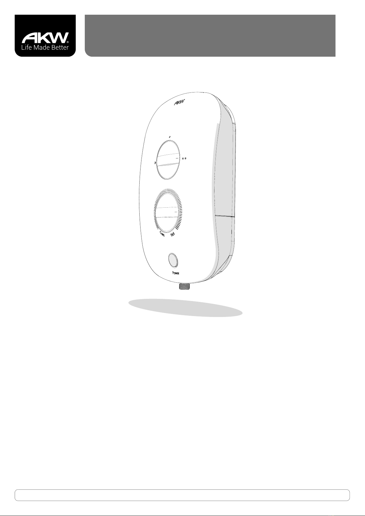
Product Features
Introduction
The iSure 2 Electric Shower has been specifically designed to allow for easy installation.
Advanced fitting innovations mean it’s quick and easy to install over most manufacturers’
footprints.
Flexible Installation
8 Water Inlet Points
8 Cable Inlet Points
Dual power blocks for left or right wiring
Over temperature Thermostatic cut-out
Retro-fit footprint
3 year warranty
8.5kW or 9.5kW options available

3
© 2021 AKW 14-009-105-01
Contents
Introduction
These instructions are provided to advise the minimum standards of installation and recommends the best practice for the installation.
Due to the very wide variability of possible installation conditions AKW cannot provide all circumstances for the installation. AKW cannot
accept any liability in connection with this information or its use. This information is provided on the condition that the person receiving
it shall make their own tests to determine the suitability for their particular purpose. None of the foregoing affects your statutory rights.
Failure to install this AKW product in accordance with supplied instructions or the making
of unauthorised modifications will invalidate any warranty and may affect product safety.
Introduction 2-3
Product Features 2
Contents 3
User 4-8
Safety Information 4
Operating Instructions 5
Maintenance and Cleaning 6
Troubleshooting 7
Warranty 8
Installer 9-16
Main Components 9
Specifications 10
Installation Requirements 11
Positioning of the Shower 12
Disassembly 13
Fitting to wall 14
Reassembly- Bottom Cover 15
Reassembly- Front Cover 16
Plumbing 17-20
Water Requirements 17
Plumbing Connections 18
Plumbing Entry Points 19
Check List 20
Electricals 21-24
Electrical Requirements 21-22
Electrical Entry Points 23
Check List 24
Commissioning 25-27
Cold Water Flushing & Priming 25
Functional Checks & Testing 26
Commissioning Record 27
General
Contact Us 31

4
© 2021 AKW 14-009-105-01
Safety InformationSafety Information
User
This appliance can be used by any persons (including children from 8 years and
above) with reduced physical, sensory, mental or intuitive capabilities or by any
persons with a lack of experience and knowledge of showering, only if they are
supervised or have had the correct instructions on how to operate the appliance
correctly.
Use it correctly and do not let children play with the appliance. Ensure that
the temperature is not set to maximum before showering. Sunburn or skin
conditions can increase your sensitivity to hot water. Make sure that you set the
shower to a cooler temperature.
Do not operate shower if you suspect the water in the heater tank is frozen or
the appliance has been susceptible to freezing conditions.
Do not operate the shower if the spray handset or hose is damaged, twisted or
blocked in anyway.
Do not restrict flow out of the shower by blocking or obstructing the hose or
spray handset.
Do not use other shower hoses and handsets with this shower. Only use AKW
approved products.
5
© 2021 AKW 14-009-105-01
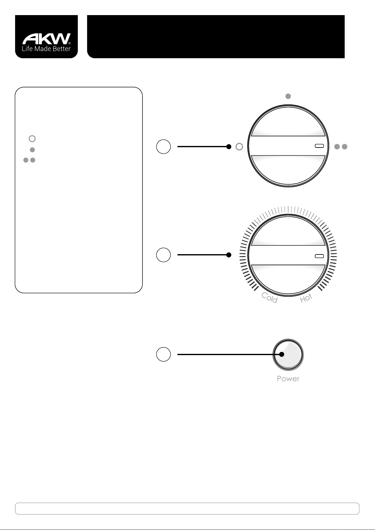
Operating InstructionsOperating Instructions
User
1. Power Level Control
Adjustable power setting:
Zero
One
Two
2.Temperature Control
Adjustable temperature control
3. Power Button
Push button to power on/off
the shower
1
2
3
Starting and stopping the shower
Switch on the mains power at the isolating switch.
When the power is first turned on, the shower is in standby mode.
To switch on, press and release the power button, the Temperature and Power Level will
be indicated on the two controls.
To switch off, press and release the power button to the stop water flowing.

6
© 2021 AKW 14-009-105-01
7
© 2019 AKW 13-012-085-17
7
User
Maintenance and Cleaning
Always isolate power supply before cleaning. Do not operate if the shower
unit is frozen. Clean and descale the shower head regularly.
The shower unit and surrounding areas should be cleaned periodically to
remove any accumulation of dirt or other waste materials, using domestic
bathroom and kitchen cleaning materials with a soft cloth.
Do not use abrasive pads or cloths. Do not use strong or concentrated
acidic, alkaline or other cleaning materials as these may damage or
discolour the product.
After cleaning always wash down with water then wipe thoroughly with a
damp soft cloth to remove any cleaning material residue.
DO NOT position the handset to spray water directly on to the appliance.
Children should be supervised at all times if they use the shower appliance
or attempt to clean it.
7
© 2021 AKW 14-009-105-01
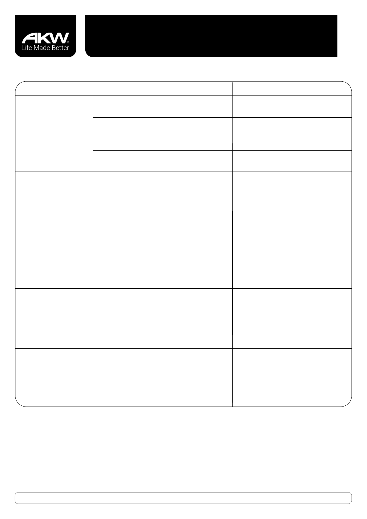
TroubleshootingTroubleshooting
User
Fault Cause Remedy
No Water Flow
Shower runs hot
and cold during use
Shower
temperature cycles
between hot and
cold
Water from
coming from back
face of shower
Water isolating valve in off position
Filter blocked
Power supply not on
Pressure Relief Device (PRD)
activated Call AKW Technical Enquiries
Clean the handset
Increase the flow by adjusting
the temperature control knob
to cooler setting.
Reduce the power setting
Water temperature
too hot
Shower temperature is set too high
causing the thermal cut out to turn
off the heating elements to reduce
the water temperature
Turn shower temperature
control anticlockwise
to reduce the water
temperature
Check running pressure
(minimum of 0.5bar)
Wait until pressure increases
Turn on water supply
Turn off water supply, remove
filter and clean
Turn on power supply
Insufficient water flowing
through the shower
Water pressure is below minimum
requirement. This may be caused
by other appliances on the same
pipework drawing water

8
© 2021 AKW 14-009-105-01
WarrantyWarranty
User
AKW guarantee your shower against any defects in manufacturing or materials for
3 years from the date of installation. Please ensure you have completed the warranty
card enclosed and return to AKW within 30 days to activate this warranty offer.
Alternatively visit www.akw-ltd.co.uk/warranty and complete the online registration
form. Within this period AKW will decide to repair or replace as we may choose.
Failure to activate warranty in set period will mean potential charges should a visit to
site be required by an AKW Maintenance Engineer. Any action taken under this
warranty does not extend the stated 3-year expiry date. Contact information can be
located on the back page. This guarantee is in addition to your statutory and other
legal rights. None of the foregoing affects your statutory rights.
Not covered by this warranty:
• Damage or defects that result from inappropriate use or accidental damage,
incorrect installation, or lack of maintenance including but not limited to the build
up of limescale, system debris or pipe scaling, grime, dirt or water-borne debris.
• Damage resulting from inappropriate cleaning or water ingress.
• Damage resulting from water freezing.
• Damage resulting from PRD activation from either a blocked hose or a blocked
shower handset.
• If the product is taken apart.
• Damage or defects that result from repairs or modifications undertaken by
persons who are not installers or AKW service engineers.
• Malfunction resulting from incorrect use.
• Failure to install in accordance with the installation instructions or performance
issues arising from incorrect installation.
• Claim for a defect identified at the point of delivery, once the product is fitted
(unless authorisation from AKW Medi-Care Limited has been granted).
• In-situ impact damage.
• Water, electrical, pressure or isolation issues.
• Wear and tear from routine maintenance, cleaning, adjustments, corrosion or
erosion.
If you need any advice or if you have any questions please contact the Technical
enquiries helpdesk with your model number and date of purchase.
For technical faults always refer to the trouble shooting guide before contacting your
local installer for assistance. If your installer should need further assistance then
contact the technical helpline on 01905 560219.
Warranty
3yr
9
© 2021 AKW 14-009-105-01
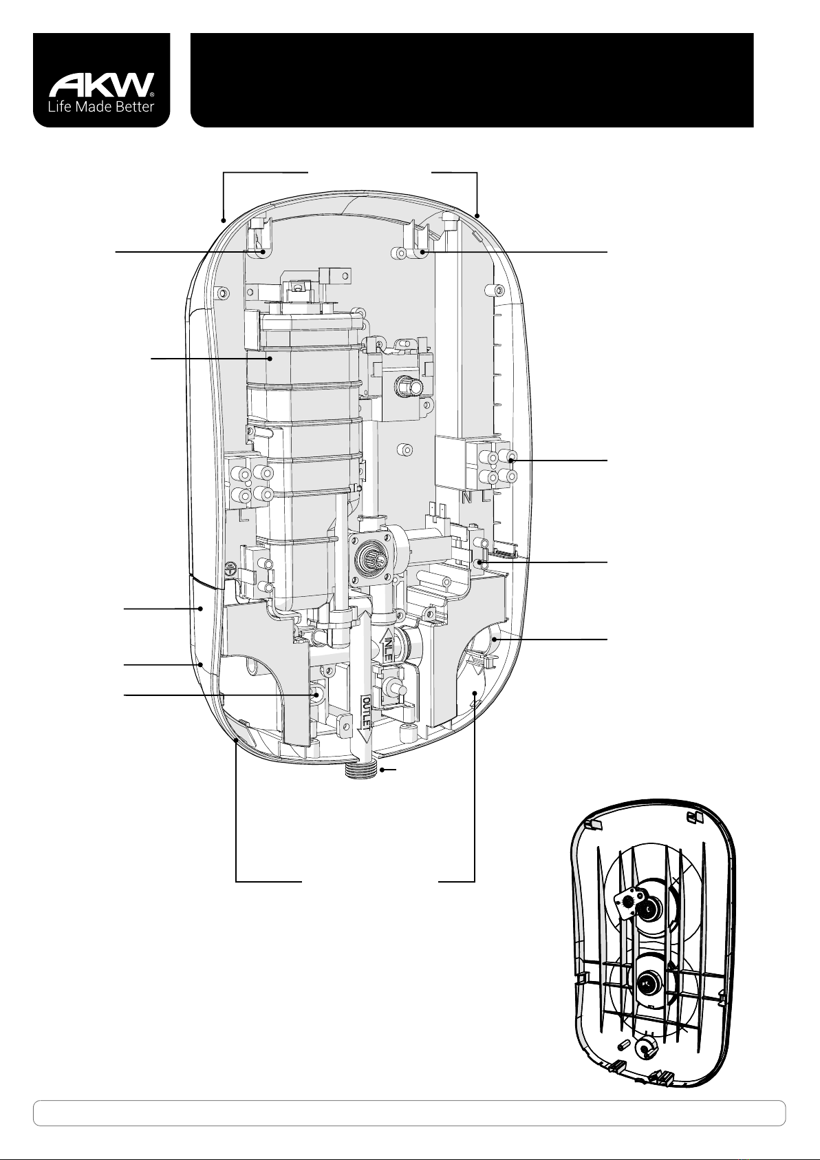
Installer
Main Components
Removable
Bottom Case
Side Pipe & Cable
Cut-out Entry
Side Pipe & Cable
Cut-out Entry
Shower Hose
Outlet
Water Heater Can
Live & Neutral Terminal
Block
Earth Terminal Block
Fixing Hole
Fixing Hole
Fixing Hole
Rear of
Front Cover
Top Pipe Inlet and
Cable Entry Cover
Bottom Pipe Inlet and
Cable Entry Cover

10
© 2021 AKW 14-009-105-01
Installer
Specifications
Supply Source Mains pressure cold water only
Minimum Dynamic Pressure 50kPa (0.5 Bar)
Maximum Static Pressure 1000 kPa (10 Bar)
Optimal Minimum Dynamic Pressure*100 kPa (1 Bar) (Recommended to ensure high performance)
Maximum Inlet Temperature 28°C
Minimum Inlet Temperature 2°C
Inlet Connection 15mm pipe
Outlet Connection 1/2” BSP Male Thread Fitting
Nominal Rating at 240 V 9.5kW & 8.5kW
Supply Fuse / Circuit Breaker (9.5kW 40/45A) & (8.5kW 35/40A)
Residual Current Device (RCD) 30 mA (must be fitted)
Supply Cable Refer to current wiring regulations
and BS 7671 to determine minimum
cable size. No larger than 10mm2
Isolation Switch (e.g. Pull Cord) 45 Amp Double pole with 3mm
contact separation.
Height (H) 380 mm
Width (W) 230 mm
Depth (D) 85 mm
Footprint Height (H2) 345 mm
Footprint Width (W2) 210 mm
Water Ingress Rating IPX4
Water and Cable Entry Points Top, bottom, side or back.
ELECTRICITY SUPPLY PLUMBING SUPPLY
PHYSICAL
(D)
(H) (H2)
(W)
(W2)
Table of contents
Other Akw Bathroom Fixture manuals

Akw
Akw TF75 Installation guide

Akw
Akw Option TT User manual

Akw
Akw SmartCare Plus User manual

Akw
Akw iSure Quick guide

Akw
Akw Arka 25421-2 User manual

Akw
Akw Onyx Exclusif User manual

Akw
Akw Onyx Duo AKW23684 User manual

Akw
Akw 30501 User manual

Akw
Akw Onyx 25436L-LS User manual

Akw
Akw Navlin 23548 User manual


