AL Guardian G9 RX User manual

USER GUIDE
AL G9 RX
www.alg9.com

Package Contents
A. Sensor Unit
B. Control Unit
A1
B2
A2
A5
B3 B4 B5
A4
A1 Outer Sensor
A2 Bracket
A3 Screws
A4 Cable ties
A5 Shrinking tube
A6 Adhesive tape
B1 Control Box
B2 Control Set
B3 Level
B4 Wire taps
B5 LED holder
B6 User Guide
A3
A6
B1
AL G9 User Guide, ed. 2009-09-28
COPYRIGHT © 2009 A-ELEKTRONIK

ImportantSafetyInstructions
READBEFOREOPERATING
This product was designed and manufactured to meet strict quality and safety standards. There are,
however, some installation and operation precautions which you should be particularly aware of.
Thereforeread,keepandfollowtheseguidelinesduringinstallationanduse:
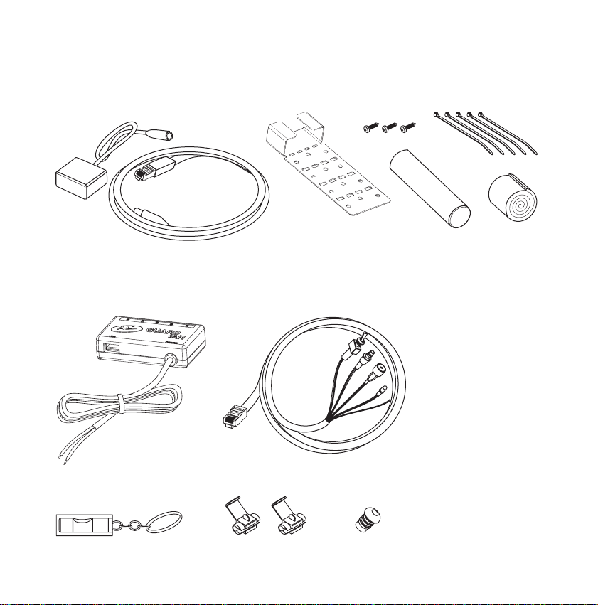
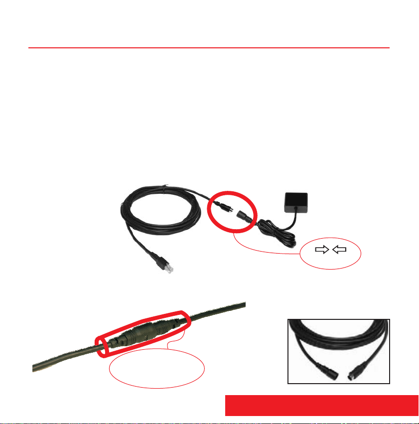
Take special care while installing the sensor head. Damaging the cable or the factory installed
connectoronthecablemaycausemalfunctionandwillvoidwarranty.
Whilethesensoriswaterresistantandintendedtobeinstalledontheoutsideofthevehicle,thecontrol
box and it’s connections must be made and kept in a dry area, preferably the passenger cabin.
Warrantywillbedeemedinvalidiffailuresarecausedbyimproperinstallation.
Do not plug more than four outer sensors into the control box. Do not plug any third party equipment
into any of the sockets in the control box. Do not plug any part of theAL G9 into third party equipment.
Doingsomaycausefireordamagetotheunitandvoidswarranty. Doing so
wouldcausecharacteristicfailureoftheunitandvoidswarranty.
It will take time to get acquainted with the range of the parking sensor, which can vary from 0 to 3
meters,fromyourcartotheobstruction.Thereforerelyonyourpersonaljudgment.
ALG9canNOTdetectglassorothertransparentobjects.
Duringwarm-upmode(first60secondsofoperation)ALG9functionsarelimited.
Whiledriving,especiallyinwintermonths,dirtandfilthcanaccumulateontheoutersensorlens,which
can affect the sensor's performance. Wipe the lens periodically with a dry or moist cloth. Do not use
cleaningsolventsotherthanwater.
Laser signals emitted from AL G9 can cause interference to other laser equipment. If such a case is
detectedbytheunitthesystemwillresetwithinfewseconds.
If the vehicle where AL system is to be installed is already using another laser system (for instance
laser cruise control, or similar) two systems could interfere with each other. Such vehicles may not be
suitableforuseofALsystem.
Use of laser products may be regulated by your local laws. Check your local laws before using this
product.
SinceAL G9 operates on a different voltage it is NOT to be mixed withAL G8 components.
Special caution
AL G9 laser sensor emits an invisible laser beam that can be harmful to sight. Never, under any
circumstanceslookatthesensorwhileitisoperating.

SafetyandConformity
Electromagneticcompatibility
Lasersafety
The AL G9 Guardian is fully in conformity with the requirements of Council Directive 2004/108/EC
Electromagnetic Compatibility (EMC), based on the full compliance of the product with the following
European/International Standards:
Emissions:EN61000-6-3(IEC61000-6-3)
Immunity:EN61000-6-1(IEC61000-6-1)
The labelling of the AL G9 which is affixed on the top of the Outer Sensor and the Control Box housing
meetstherequirementsoftheguideline2004/108/EC:
The AL G9 Guardian is fully in conformity with the requirements of Automotive EMC Directive
2004/104/EC amended by directives 2005/49/EC, 2005/83/EC, 2006/28/EC and approved by State
OfficeforMetrologyofRepublicofCroatiawithapprovalnumber10R-020004.
The AL G9 is tested and classified as Class 1M laser product in accordance to European and
InternationalEyesafetyregulationsEN60825-1andIEC60825-1.
Definition: Class 1M-laser products are safe under reasonably foreseeable conditions of operation, but
maybehazardousiftheuseremploysopticswithinthebeam.
AnOuterSensorunitoftheALG9systemislabelledinaccordanceto regulations:
ForproductsdeliveredintotheUnitedStatesthefollowingclauseapplies:
Complieswith21 CFR1040.10and1040.11exceptfordeviations pursuanttoLaserNoticeNo.50,dated
July26,2001.

Table of Contents
1. Introduction 1
2. Main Parts of the Product 3
4. Usage 9
5. Specifications 13
6. Operation description 14
4.1 Operating modes 9
4.2 Additional features 12
4.1.1 Detection range adjustment 9
4.1.2 Silent power-up 10
4.1.6 Parking sensor mute 11
4.2.1 Speaker mute 12
4.2.2 Restore factory default settings 12
4.2.3 Manual sensor check 12
7. Registration, warranty and service 15
Revision X Improvements 2
Installation diagram 7
4.1.3 Laser interference defense (LID) adjustment 10
4.1.4 LED Dark mode 10
4.1.5 Laser Power Output 11
3. Installation 4

Thank you for purchasing AL G9 GUARDIAN, designed for
yourdrivingcomfortby A-ELEKTRONIK,Croatia.
The G9 comprises and was designed to keep you and
your vehicle safe by ing g. As
opposed to classic infra-red sensors that use light emitting diodes AL G9 is equipped with a
laser diode that is used in military range-finders and police speed detectors, the power of
which is one hundred times greater than that of a LED diode. In addition, it incorporates the
newlaserdetectiontechnologythatisasignificantimprovementintheindustryandwillensure
higherprecision,morereliabilitywith highresistanceto temperaturechangesand foreignlight
interferences,specificallySunrays.
The G9 works on the 905 nm light frequency. It constantly emits laser signals and recognizes
them if they return reflected from an obstacle, consequently warning the user. Thanks to the
advanced program code the G9 will differentiate the laser signals coming from other laser
sources.
If an AL Driveway Unit (an option) is installed in your driveway or garage the G9 becomes a
drivewaylightactivatorand/oragaragedooropener.
a multipurpose parking sensor
parts fabricated to military standards
enabl effortless parking and greater confidence while drivin
Aswecontinuetoworkondevelopingnewproductsandsupplyconstant improvementstoour
existingproductswethankyouforthesupportgivenbythispurchase.
ALG9ispatentpendingaccordingtoPCT/HR2008/000015.
1. Introduction
1 AL G9 User Guide

Revision X Improvements
AL G9 superior laser detection is achieved by completely new electronic and computing
design of the reception system. The unit's memory has been doubled enabling new program
featurestobeadded.
Thelatesthardwarerevisionbringsmoreadvancements:
-waterproofconnector1meterfromthesensorforeasierinstallation
-thickshieldedcablepreventsengineinterferenceandmechanical damage
-cablestressreliefisnowinsidethesensormakingitsmaller
-optionalextensioncablesavailabletofittoanylength
-improvedlasersensitivity(+15%)
- improved power filtering against power line noise
- fully effective from 10V to 17V power supply
- improved parking assistance performance
- even wider angle protection (up to ±12°H ±12°V)
- Control Box now comes with plug in Memocard enabling quick upgrades by end users
IMPORTANT NOTE: The G9 uses lower voltage and less current
consumption and is NOT compatible with AL G8 components.
2AL G9 User Guide

1) 4 S sockets for front/rear sensor connection
2) C socket for control set connection
3) USB socket for AL G9 additional feature modules
s
Outer Sensor
Incorporatesemittinganddetectioncircuits:includesoneemittingandfourreceptiondiodes.
As this unit is installed on the outside of the vehicle, it is specially
protected from water and mechanical damage. Sensor cable is 1 meter
long ending with a waterproof connector. The product set can consist of
onetofouroutersensors.
Control Set
Acable with a C connector on oneend which should be connected to the C socket of the Control Box.
Theotherendofthecableconsistsofcontrolsthatinclude:
speaker,
two-colorlightdiode,
programmingkeybutton,
mutewireforcarstereo.
on&offswitch,
2. Main parts of the Product
Control Box
The central part and the brain unit of the AL G9. It
includes a processor, a removable Memocard with
, a complex power
supplyunitandthefollowingsockets:
upgradeable flash memory
3 AL G9 User Guide

To obtain the best performance of yourALG9 and insure long service life, seek a professional installer to
mounttheproduct.TobegininstallationfollowthesestepsandrefertotheInstallationdiagram.
OUTER SENSOR
Can be mounted between the front grill partitions or above the rear bumper. Take care not to damage the
cable or the factory installed connector on the cable during installation (cutting the cable or removing the
factoryinstalledconnectorvoidswarrantyandmaycausemalfunction).
Checkifthecableislongenoughtoreachthedesiredposition.TheRXs
otal of 5 meters in lenght can be reached. Longer
rangecanbeachievedbyaddinganExtensioncable(2,5meters,purchasedseparately).
To achieve maximum water resistance put a heat shrink tube (included) on the connector. Use a
strong heater for the tube to shrink and conform to connector size.
jensorcable(1meter)istobe
connected with a connecting cable (4 meters). At
The tube can be torn apart when
thesensorrequiresdisconnection. OPTION: 2,5 m Extension cable
Heat shrink tube provides
total humidity protection.
We strongly advise you
to use it.
3. Installation
arrow to arrow
4AL G9 User Guide

k
l
Attachtheunitusingdouble-sided adhesivetape andamountingbrackettoaposition thatoffers
a clear front (back) view. The mounting bracket can be bent as needed. Make sure the sensor is
installed firmly in order to absorb vibrations that occur while driving, especially if mounted on a
motorbike.Formaximumgripuseanadhesivetapeincombinationwiththemountingbracket.
If installing sensors behind flat surfaces (plastic bumpers, dens grills) it will be necessary to drill
holes through which the sensor will have unobstructed view of the road. Two circles on the
sketchofthesensorlensrepresentarea
wherereceivingandemittingdiodesare
positioned. These circles must be clear
of obstruction while the rest of the lens
can be covered if needed. Obstructing
surface should not be more than 1 cm
away from the sensor lens, or larger
holes should be drilled to maintain
angleprotection.
Makesurethesensorislevelled(usealeveltocheck).
5 AL G9 User Guide

CONTROL BOX
The Control Box is to be mounted in the interior of the vehicle at the place of your choice and it should not
beexposedtowater.
4 Locateaccesstothepowersupplyofthevehicle(+12V)
5 Connect the Control Box wire to the positive battery lead and Control Box wire to the
ground lead or the car chassis. If using the supplied wire taps (to be used only on a wire of the
appropriate size) insure that they are properly locked and preferably wrap them with insulation tape
afterwards.
6 Afterthecontrolboxisconnectedtothebattery,connectthesensorintooneoftheSsockets.Ifhaving
morethan1sensorconnectallofthem,theirorderisnotrelevant.
BLACK
(1A fuse is factory installed inside the Control Box but if required additional fuses can be installed externally in the
wiring.)
RED
RED
To avoid the possibility of draining your car battery by accidentally leaving your AL G9
system on for prolonged time, use the following connection method instead of the one
describedabove:
7 Define where to install each control in the vehicle interior while keeping in mind that the on&off switch
andprogrammingkeybuttonshouldbeclose
athandandthatthetwo-colorlight diodeisin
sight while the speaker should remain within
rangeofthedriver.UseaLEDholder
supplied with the installation accessories
wheninstallingatwocolorLEDdiode.
8 ConnecttheCconnectortotheCsocketoftheControlBox.
9 Connect the blue car radio mute wire to the corresponding audio mute input on the car radio, if it has
one.
Connect the BLACK Control Box wire to the car chassis or to the negative ground power
supply wire of your vehicle's system and connect the Control Box wire to the SWITCHED
positive power supply wire usually found in the car radio power supply.
CONTROL SET
hearing
OPTIONAL: If using a Control
Set in a Box instead of
installing each control
separately mount the box in a
clearlyseenposition.
6AL G9 User Guide

Installation diagram on & off switch
programming key button
speaker
two color LED
mute wire
black red
a battery

Turn on yourAL G9 set. The activation isfollowed by an intermittent sound coming from the speaker and
alternating red and green flashing diode lights. While active the green light will flash once every second.
With every activation the set runs a self-test; if the set has not been connected properly or has a
malfunction,thereddiodewilllightupaccompanied byawarningtone.Whenanobstacleisdetectedyour
ALG9 willwarnyouwithred diodeflashesandaudiblesignals thatwillbecomefasteras theobstaclegets
closertotheoutersensor.Youwill also be warned with fast red flashes and speakertonesincaseoflaser
interferencedetection.Moreonoperationmodesandaudio-visualsignalscanbefoundonpage14.
ALG9 has 6 user selectable operating modes which are set to optimal default values but can be modified
by using the programming key button at any time during the operation of AL G9. After been modified
operatingmode willremain permanentlywritteninthememory ofthe processor.Someadditionalfeatures
willbeintroducesfurtheron.
4.1.1Detectionrangeadjustment(DEFAULT:LEVEL2)
Before using the parking sensor in driving conditions it should be tested with a piece of paper or another
object.Awarningtone willbeheard,accompaniedbytheredflashinglightasyoubringthepaperorobject
closertothe sensor. Ifneeded,the detection range(whichcanvary from 0to3meters) can beadjustedto
fourdifferentlevelsbyusingtheprogrammingkeybutton.Usethefollowingsequenceforreprogramming:
Pressandholdthekeybuttonwhilecountingtheflashinggreenlight.
Releasethekeybuttonafterthethird(3)flash.
AL G9 will reprogram accompanied by red and green flashing lights and speaker tones. Long
tonescomingfromthespeakerduringreprogrammingsymbolize fourdifferentdetectionlevels:
1toneforLEVEL1(shortmode);
2tonesforLEVEL2(mediummode);
3tonesforLEVEL3(longmode);
4tonesforLEVEL4(extralongmode).
Thedetection range levelsalternateand you willneedto reprogram thesetseveral timesbeforereaching
thedesiredsetting.
4.1 Operating modes
3
4. Usage
9 AL G9 User Guide

4.1.2Silentpower-up(DEFAULT:OFF)
Duringactivation,only redandgreenindicatorlightswillflashwithoutsounds.Usethefollowingsequence
toactivate/deactivatethisfeature:
Pressandholdthekeybuttonwhilecountingtheflashinggreenlight.
Releasethekeybuttonafterthefifth(5)flash.
ALG9willreprogramandthiswillbesignalledbyredandgreenflashinglightsandspeakertones.
4.1.3Laserinterferencedefense(LID)adjustment(DEFAULT:4SEC)
AL G9 possesses an advanced program code for detecting and deflecting possible interference signals
fromothersources of laser emissionsonthe905 nm frequency.When a constantinterferenceisdetected
and recognized as an aggressive disturbance for the parking sensor operation, AL G9 will try to ensure
maintaining its reliable performance. During this time the user will be warned by a four second tone from
the speaker and a red flashing light that a parking sensor operation has become unreliable. If the parking
sensor operation is not recovered within 4 seconds and the interference continues the unit will
automaticallyreset.
To prevent the green light from flashing every second during normal operation, you can activate the LED
Dark mode. The green light will stop flashing after the warm-up period (60 seconds after the power-up) if
thismodeisactivated.
You can choose between 4 seconds and 8 seconds duration of eventual interference detection and
deflection.Thismodecanbeprogrammedwiththefollowingsequenceonthekey button:
Pressandholdthekeybuttonwhilecountingtheflashinggreenlight.
Releasethekeybuttonaftertheeighth(8)flash.
AL G9 will reprogram accompanied by red and green flashing lights and speaker tones. Ashort
tone coming from the speaker during reprogramming indicates the 4 sec mode being selected while the
longtoneindicatesthe8 sec mode.Thelimitdurationsettingsalternate so please repeat the sequence to
returntothepreviousstate.
4.1.4LEDDarkmode(DEFAULT:OFF)
5
8
10AL G9 User Guide

Usethefollowingsequencetoactivate/deactivatetheLEDDarkMode:
Pressandholdthekeybuttonwhilecountingtheflashinggreenlight.
Releasethekeybuttonafterthetenth(10)flash.
ALG9willreprogramandthiswillbesignaledbyredandgreenflashinglightsandspeakertones.
Choose between the optimal and maximum laser power output modes. Using optimal setting
(recommended) will reduce the possibility of error detection while maximum power insures maximum
rangeandenergy.Toreprogramthismodeusethefollowingsequence:
Pressandholdthekeybuttonwhilecountingtheflashinggreenlight.
Releasethekeybuttonafterthethirteenth(13)flash.
Tone with LED flashing red indicates MAXIMUM setting selected while tone with LED flashing
greenindicatesOPTIMALsettingbeingselected.
4.1.5LaserPowerOutput(DEFAULT:OPTIMAL)
4.1.6Parkingsensormute(DEFAULT:OFF)
With this mode activated the parking sensor will warn you of an obstacle detected only with red flashing
lights, while in default setting the light would be accompanied by warning tones from the speaker. To
activate/deactivatethismodeusethefollowingsequence:
Pressandholdthekeybuttonwhilecountingtheflashinggreenlight.
Releasethekeybuttonaftertheeighteenth(18)flash.
ALG9willreprogramaccompaniedbythreeshortredflashes.
10
13
18
11 AL G9 User Guide

4.2 Additional features
4.2.1Speakermute
4.2.2Restorefactorydefaultsettings
4.2.3Manualsensorcheck
The key button is useful in city driving as a single 1 second press will switch the speaker off
andfurtherparkingsensorwarningswillbegivenjustbyredflashinglights.
Thissettinglastsuntilthesetisturnedoff.
Didyouforgetwhichfeaturesyouprogrammedintoyoursystem?Usethissimpleprogrammingsequence
torestorefactorydefaultsettings:
Pressandholdthekeybuttonwhilecountingtheflashinggreenlight.
Releasethekeybuttonafterthefifteenth(15)flash.
ALG9willreprogramaccompaniedbyconstantgreenlightandlongerspeakertone.
While restoring factory default settings the unit will count and memorize the number of
sensors connected to the system. On each subsequent power-up during the self-test
process the unit will check if all memorized sensors are present and operational. If one or
more of them is disconnected or not operational you will be warned by five 2 seconds long
tonesandredflashesduringfirst15secondsofoperation.
NOTE: In order to memorize the new setup initiate this setting after installation of every new
sensor.
To manually check the number of sensors connected and operating in the system use the following
programmingsequence:
Pressandholdthekeybuttonwhilecountingtheflashinggreenlight.
Releasethekeybuttonafterthetwentieth(20)flash.
The number of long tones coming from the speaker shows how many sensors are found
connected.
Automatic sensors check
1
15
20
12 AL G9 User Guide

Dimensions:
Outer Sensor (LxHxW)
Control Box (LxHxW)
Control Set (L)
Weight:
Outer Sensor
Control Box
43x20x50 mm (1,7x0.8x2.0 in)
Cable length:1m+4m(16.4 ft)
85x22x40 mm (3.3x0.8x1.6 in)
Power supply cable: 1 m (3.3 ft)
1,5 m (4.9 ft)
105 g + 160 g (0.26 lb + 0.4 lb)
110 g (0.27 lb)
Working temperature:
Power:
Operational power supply
Current consumption
Speaker loudness:
Laser class:
Laser wavelength:
-20 °C to +60 °C (-4 °F to 140 °F)
10Vto17V
600 mA max.
90 dB
1M
905 nm
13 AL G9 User Guide
5. Specifications
Specifications are subject to change without notice.

Operation :
Activation mode
Warm-up mode
Search mode
1secondfollowingpower-up;self-test
60secondsfollowingtheActivationmode;duringwarm-upmodeALG9functionsarelimited.
Theendofawarm-upmodeissignaledwithagreenLEDflashandatonefromthespeaker.
Searchingforobstacles;Otherfunctions
LED & sound signals:
LED flashing green
LED flashing red + tone
LED constant red + tone
LED constant red + 1 beep
LED constant red + 2 beeps
LED constant red + 3 beeps
LED flashing red + beeps during first 15 seconds of operation
Normaloperation,LEDflashesgreeneverysecond
Obstaclefound
Interferencedetected;LIDactivated
Faultyoperation;lowvoltage,checkvehiclepowersupply
Faultyoperation,cablesunpluggedordefectiveunit,checkcables
Warning sensor unplugged, not properly mounted or a defective sensor, check sensor
Automatic sensor check failed, check sensor connections. If adding or removing sensors
perform code 15 (restore factory defaults).
6. Operation description
14AL G9 User Guide

Registration
To become a Registered owner o
Phone:+38513643890
www.a-elektronik.hr
Wholesales:
Radikald.o.o.(ltd.)
Sesvete-Croatia
www.alg9.com
f theALG9 please send a registration inquiry no later than 30 days from
thedateofpurchaseto .
Whytoregister?
If you register, you get once a year free Memocard with the latest firmware sent to your address directly
fromthefactoryonyourrequest.
Onlyregistereduserswillreceivenewslettersandgetspecialdiscounts.
To find out if there is a program code upgrade available for your system, send an inquiry to
orcontactyourlocaldealer.
The manufacturer guarantees that the product is fully functional. During production and before delivery it
undergoes numerous quality checks. Nevertheless, a limited two years warranty will apply, valid from the
date of the first purchase. If you have not registered your product in case of warranty claim you are
required to show an original receipt with a visible date of the purchase and a warranty card authorized by
thedealer.Thewarrantytermsaredefinedinthewarrantycard,hereincluded.
If uncertain whether yourAL G9 is working correctly please check Operation description, page 14 of this
manual. If it does not give you a solution to your problem contact your local dealer or our Service and
Supportcenterat .
Serviceandsupportprovidedbythemanufacturer:
A-ELEKTRONIK,Zagreb,Croatia
Warranty
ServicingandSupport
7. Registration, warranty and service
15 AL G9 User Guide

RX Control Box with plug in Memocard
SN: XXXXX
Memocard
plug in spot
Remove Control Box protective
label but do not remove small
serial number label
Unscrew 5 screws and open the box
Unplug the old Memocard and plug
in the new one
Close the Control box and stick a new label over the 5th screw
IMPORTANT NOTE: 1 protective label is delivered with every Memocard. Do not
remove the original label unless you have a spare one. Control boxes without
protective labels over the 5th screw will be considered warranty void.
Upgrade by exchanging the Memocard
Table of contents
Popular Automobile Electronic manuals by other brands

Connects2
Connects2 CTUKI01 instruction manual

Radio Shack
Radio Shack 63-1007 - Ultrasonic Parking Alert System owner's manual

Audicom
Audicom C100 Service guide

BENDIX
BENDIX Wingman Fusion Operator's manual

Directed Electronics
Directed Electronics VIPER 4103XV owner's guide

BMW
BMW Apollo 84 61 0 143 955 installation instructions

Toyota
Toyota PW501-02010 installation instructions

Dynojet
Dynojet SFM-10 installation instructions

Renault
Renault 8201373014 installation instructions

Jacob Jensen
Jacob Jensen Electronic Parking Disc 3 quick guide

Murphy
Murphy PowerView PV1000 Hardware installation manual

sametech
sametech park solar DIGITAL user manual