Movon MDAS-3LFFHD User manual

(Movon Driver Assistance System –3LF)
MDAS-3LFFHD
User Manual
1

2
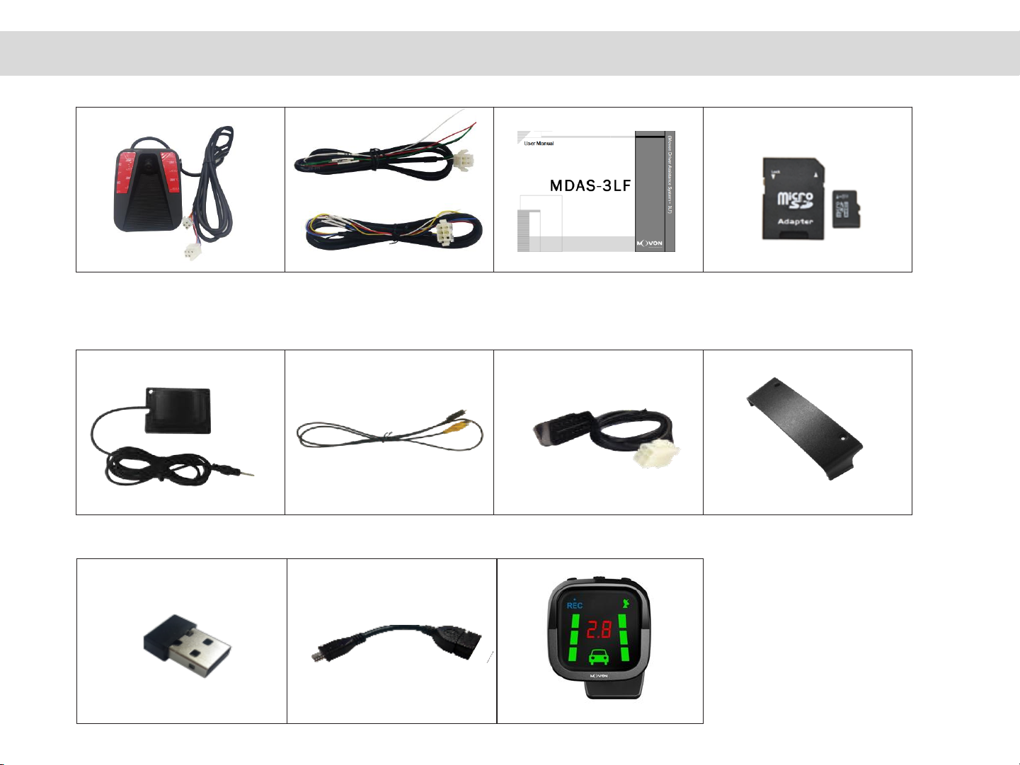
Thank you for purchasing Movon Advanced Driver Assistance System –3LF (MDAS-3LFFHD).
Please read the manual carefully before installing and using MDAS-3LFFHD.
•Any inappropriate or illegal activities or violation of traffic rules on the roads are drivers’ responsibility. Movon Corp. will not compensate any damage
nor accept responsibility related to behaviors mentioned.
•Please be aware of Movon’s policy that private information and traffic related laws are users’ responsibility.
MDAS-3LFFHD only gives warnings to drivers. The final decision to maneuver / control shall be made by rivers themselves.
•The safety function performance might be affected by road environments, weather conditions and installations.
•Customer service incurred by controlling while driving or damaging / revamping will not be guaranteed by Movon’s policy.
•The information may not be up-to-date on the user manual for upgrading or editing purposes. The manual can be modified at any time without
notification in order to enhance software.
•The product software is able to be modified for upgrading for better performance without informing in advanced. Please refer to the
httyp://www.movon.co.kr or http://www.mdas.co.kr for latest updated information.
* Warning s / Cautions : Violating the following precautions may result in personal injury, death, or property damage.
•Do not install in disregard of installation instruction. It is recommended to go to authorized workshop or professional installation shop.
•Do not use damaged/modified cables or voltage out of the rated voltage. It may cause injury, death, or property damage.
•Do not attach MDAS-3LFFHD in which it can obstruct the driver’s view.
•Do not operate while driving, it is prohibited by law. If it is necessary, operate after stopping at a secure area.
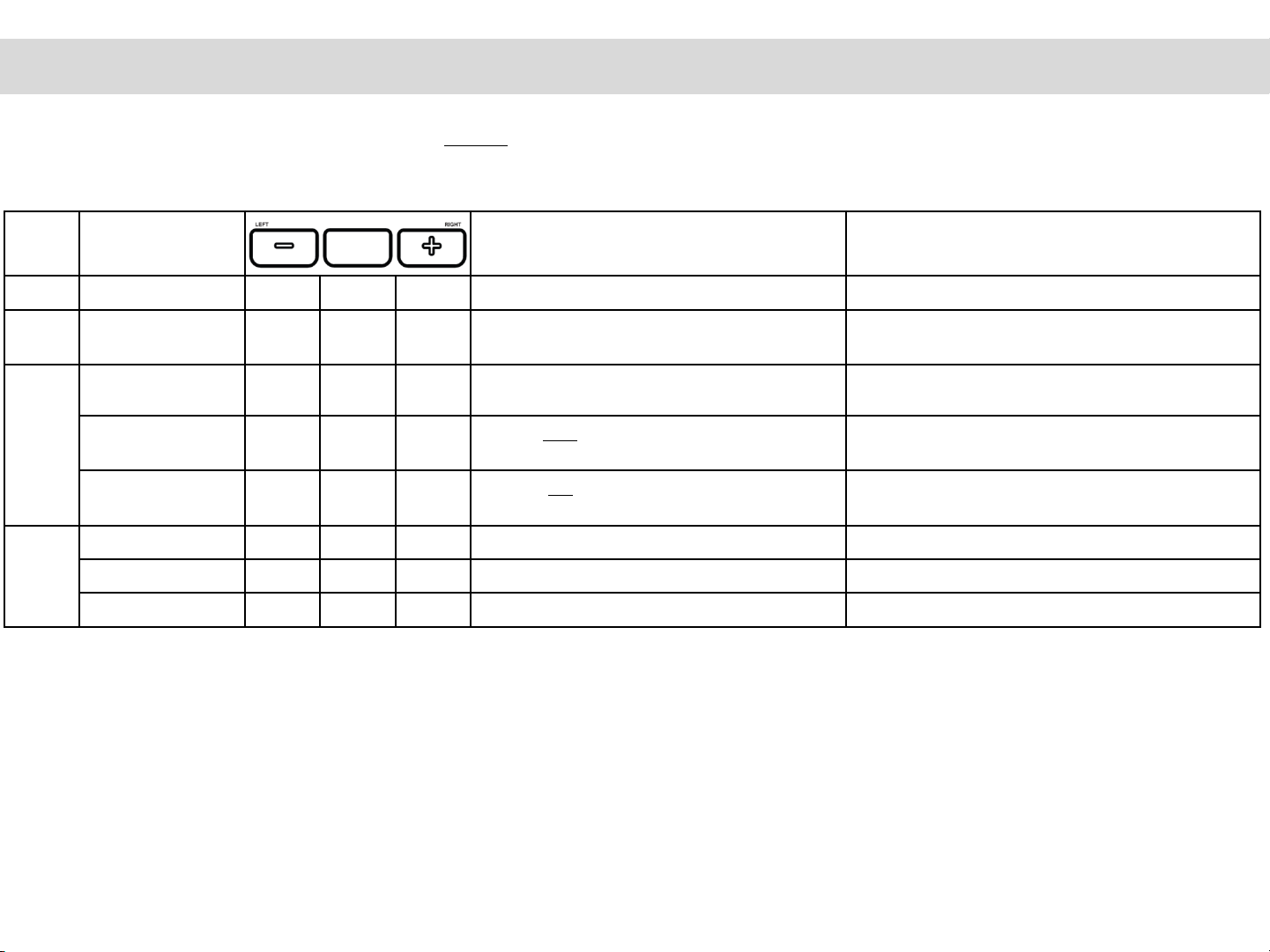
•Do not apply excessive force when pushing the buttons on the device.
•Do not leave the product where infants, children, or pets can reach it.
•Do not use chemical on the device. It can cause fire or electric short, or malfunction of the device.
•Do not separate micro SD card from MDAS-3LFFHD while the power is on. Separate after turning off MDAS-3LFFHD if it is necessary.
•Do not modify nor disassemble the product and cables. It can cause explosion or fire resulted in injury or property damages.
•Operating temperature is 4 ℉~ 158℉(-20 ℃~ 70℃). MDAS-3LFFHD may not operate properly and be damaged in excess of the temperature.
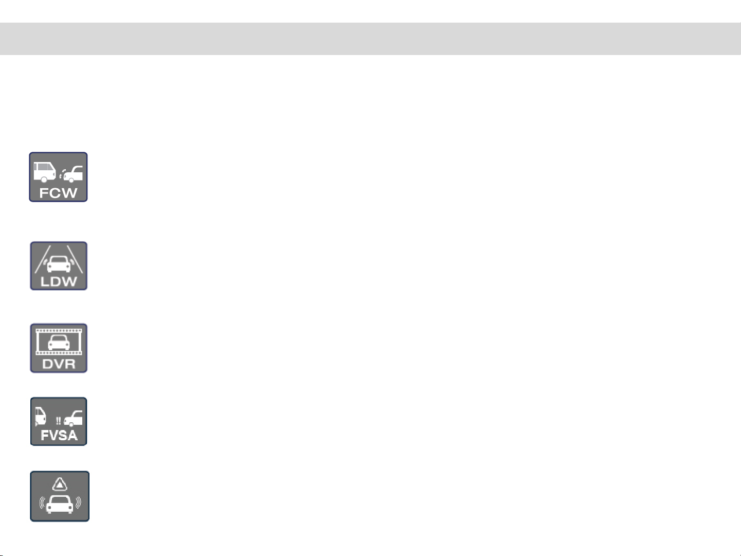
•Forward collision warning, Lane departure warning may not work properly due to camera location and angle, excessive tint, weather conditions.
•Recorded videos are only for personal use purpose. The video quality is not guaranteed to prove plate numbers or specific images.
•If the product is damaged or the power supply is cut due to an accident, video may not be recorded.
•While entering or exiting a tunnel, during daytime in the face of bright sunlight, or at night with no lights, the quality of recorded video can deteriorate.
•Foreign substance or finger print on the lens may cause improper safety function performance.
If recorded videos are broken due to users mishandling, the damaged video is not guaranteed to recover.
Copyright 2013 by Movon Corporation. All Rights Reserved.

Contents
3
1. About MDAS-3LFFHD …………………….…
2. Specification …………………………….……..
3. Components …………………………….……..
4. Part description ……………………….…….
5. Button description …………………….……
6. Operating LED status ……………………….
7. Indicator ………………………………………….
1. Cabling overview ………………………..….
2. Installing ………………………………...……
1. OBD-II Adaptor
2. Analog hard wire
1. PC calibration………………………….……….
1. Menu description ……………………………
1. Forward collision warning …….………
2. Lane departure warning
3. Dashcam
4. Tachograph
5. Video out description
……………………………………………………….……
7
8
9
10
11
12
13
16
17
21
30
35
41
1) About Product
2) Installation
3) PC calibration
4) Setting modification
5) Function
6) Warranty information

Forward Collision Warning (FCW)
Assists the driver to keep the safe distance from the front vehicle as the driver’s preset distance as
well as It warns the driver of an impending crash with audio and visual warnings.
(Active from 18mph, 30km/h)
Lane Departure Warning (LDW)
Provides lane departure warning for safe driving. It alerts the driver of sound and visual warnings
and helps to regain direction if the driver departs lanes unintentionally.
(Active from 35mph, 45km/h)
Digital Video Recording (DVR) - Parking recording is not supported
Records scenes before and after an accident along with imminent crash situations. DVR function
records data into micro SD card every minute in a loop
Front Vehicle Start Alarm (FVSA)
Notifies the driver if the front vehicle starts to move forward from 0 speed (complete stopped
status) and the driver’s car is not moving within 2 seconds.
Forward Proximity Warning (FPW)
Notifies the drive when there is a vehicle existing in the detection range and the driver’s car moves
forward. Detection range can be setup as 1.2m / 2.0m / 3.0m (Active from 0 ~ 18 mph or 30km/h )
* Configuration settings can be modified for better performance without notifications.
1.About Product
1.1 Product Overview
Movon Advanced Driver Assistance System ( MDAS ) helps to drive safely by using a machine vision recognition
technology to prevent drowsy or reckless driving.
[ Main functions ]
4

1.About Product
CPU
Cortex A7 Dual-Core
Audio Out
Speaker
Camera
1080p ( Sony IMX322 )
Power
Input Range
DC 10V ~ 36V
Power
Consumption
200mA @ 12V Max
0.3mA @ 12V Idle State
Format
Video
AVI (h.264 codec: VGA / 30fps)
Audio
PCM
Storage
4~32GB Micro SD card support
Input /
Output
USB 2.0 Device Host ( for PC Calibration, supported accessory)
Analog Video Out, GPS port, Micro SD Card, GPIO(Cable)
Size
Body
120 x 88 x 50 mm
Operating
Temperature
Optimal
-20℃~ 70℃( 4℉~158℉)
Max.
-40℃~ 85℃( -40℉~185℉)
5

[ Main Unit ] [ 6pin Power cable ]
[ Analog Cable ] [ User Manual ] [ Micro SD card ]
■Option Accessory
[ Video Out cable ] [ OBD-II Adapter ]
[ GPS Module ] [ Anti Temper Cover]
[ Wi-Fi dongle OTG cable ]
[ Wi-Fi Dongle ]
1.About Product
1.3 components
6
[ indicator ]

1.About Product
1.4 Part names
Double side sticker Speaker Main cable
Panic Recording
FCW sensitivity setting
Volume down
Camera lens
Micro SD
card slot
GPS port
Video out port
5pin USB port
Angle adjustment lever
Left LDW sensitivity setting
7
Volume up
Right LDW sensitivity setting

1.About Product
1.4 Main Cable Port
8
6pin CAN/Power connecter
4pin Analog connecter
Indicator connecter
Or RS232 for FMS

Mode
Function
Description
Voice Guidance
DVR
Panic Recording
○
Start Video Recording.
Recording
FCW
FCW
Sensitivity Change
◎
Change “Forward Collision Warning” sensitivity.
(Level 1~5)
FCW setting.
LDW
LDW On/Off
○
○
Turn on/off “Lane Departure Warning” function.
On: Starting LDW system.
Off: Ending LDW system.
Right LDW
Sensitivity Change
◎
Change Right “Lane Departure Warning” sensitivity.
(Level 1~5)
Right LDW setting.
Left LDW
Sensitivity Change
◎
Change Left “Lane Departure Warning” sensitivity.
(Level 1~5)
Left LDW setting.
ETC
Volume Up
○
Volume up
(Increasing sound)
Volume Down
○
Volume down
(Decreasing sound)
Factory Reset
◎
◎
◎
Restore MDAS-3LFFHD to factory settings.
Defaulting MDAS system. (Rebooting)
1. About Product
◎: Hold for 3 seconds
○: Press once
NOTE: +, - buttons are used to change degrees of sensitivity after entering each function.
1.5 Button Description
9
LDW/FCW
To exit setting changes, press the center button or no input for 7 seconds.

1. About Product
1.6 Operating Status
Mode
LED buttons
Description
Voice Guidance
After booting (Power cycle)
Power on
Green
The center LED will be green after booting.
MDAS is on
GPS connection check
Green
Check Whether GPS is connected in the
system.
GPS is connected
GPS is disconnected
Micro SD card check
- If there is any trouble
Amber
Green
Amber
Check whether micro SD card is inserted and
ready to record.
SD card is not inserted
Firmware update check
- If a new firmware is detected
Green
Green
Green
Check if there is a new firmware, and when it
detects, ask if the user wants to proceed.
New firmware is detected. Press
the center button if you want to
upgrade. Please leave engine
running and wait.
PC calibration
- If USB port is used
Amber
When USB port is connected to a computer
for calibration or recalibration
Entering PC calibration mode
Default the system
Amber
Amber
Amber
Default MDAS system to the factory setting
Defaulting MDAS system.
LDW/FCW
NOTE: Icons indicate The color in LED is blinking
The color in LED is changing left to right
10
CAN-related Error
Amber
MDAS-3LFFHD can not read a Vehicle’s CAN
data.
Camera-related Error
Amber
MDAS-3LFFHD can not receive video from a
camera.
Indicator-related Error
Amber
The communication between MDAS-3LFFHD
and Indicator is not working properly.

1. About Product
1.6 Operating Status
Mode
LED buttons
Description
Voice Guidance
While driving
*Safe Following Distance, Safe Distance Alarm,
Car detection & TTC alarm
Amber
When front cars are detected and it is in the
range of TTC alarm setting.
One short-beep sound
FCW alarm
Amber
FCW alarm activates
FCW alerting melody
LDW Function On
Green
When LDW is turned on
Starting LDW. (When it is on)
LDW Function Off
Amber
When LDW is turned off
Ending LDW.
LDW alarm (Left)
Green
Left LDW alarm activates
LDW alerting melody
LDW alarm (Right)
Green
Right LDW alarm activates
LDW alerting melody
LDW/FCW
NOTE: Icons indicate The color in LED is blinking
The color in LED is changing left to right
11
LDW and FCW is not working
Amber
The weather is not good. Ex) Heavy raining,
foggy, snowing.

LDWActive
LDW isenabled.
LDW Unavailable
LDW is notactive.
Left DepartureAlert
Whenthe vehicle departs the left lane.
Right DepartureAlert
Whenthe vehicle departs the right lane.
Front VehicleDetection
When the vehicle ahead is in the host vehicle’s lane.
Forward CollisionWarning
Indicates impendingcollision with the vehicle ahead.
12
Volume/Sensitivity Down
Mode setting Volume/S
ensitivity Up
1. About Product
1.7 Indicator

Recording without voice
DVR function is working and voice is not beingrecorded.
Recording withvoice
DVR function is working and voice is beingrecorded.
CameraError
Camera connection is not good. Contact your local distributor/installer.
CAN CommunicationError
CAN Communicationhas a problem. Contact your local distributor/installer.
Low Visibility Indication
The performance of ADAS might be limited under the inclement weather condition or in cas
e the vision sensor is covered by something.
13
1. About Product

ModeSelection
1) Working Mode
When it turns on, working modeoperates.
Volume control is available, when indicatoris in the working mode.
Press the (-) button repeatedly to decrease the volume, press the (+) button repe
atedly to increase thevolume.
2) Brightness Control Mode
Press the center button once it changes to brightnesscontrol mode.
Press the (-) and (+) button to decrease or increase the brightness level and sav
e the new settings. The brightness level appears in numbers.
Press the center button again, it goes to left LDW sensitivity control mode.
If there is no button operation for 5 seconds, it returns to working mode. Th
ere are five availablelevels(1-5).
3) Left LDW Sensitivity ControlMode
Press the center buttononce it changes to left LDW sensitivity control mode.
Press the (-) and (+) button to decrease or increase the left LDW sensitivity and
save the new settings. The left LDW sensitivity level appears in numbers.
Press the center button again, it goes to Right LDW sensitivity control mode.
If there is no button operation for 5 seconds, it returns to working mode.
There are five availablelevels(1-5).
Display Turning Off : Press the center button until the display turns off
(Even if the display turns off, it gives a warningsound)
Display Turning On : Press the center button.
20
1. About Product
1.8 Indicator Setting

4)Right LDW Sensitivity ControlMode
Press the center button once it changes to Right LDW sensitivity control mode. Press
the (-) and (+) button to decrease or increase the right LDW sensitivity and save the n
ew settings. The right LDW sensitivity level appears innumbers.
Press the center buttonagain, it goes to FCW sensitivity control mode. If there is
no button operation for 5 seconds, it returns to working mode. There are five avail
ablelevels(1-5).
5) FCW Sensitivity Control Mode
Press the center buttononce it changes to FCW sensitivity controlmode.
Press the (-) and (+) button to decrease or increase the FCW sensitivity and save the ne
w settings. The FCW sensitivity level appears innumbers.
Press the center button again, it goes to FPW sensitivity control mode. If there is
no button operation for 5 seconds, it returns to working mode. There are five avail
ablelevels(1-5).
6) FPW Sensitivity ControlMode
Press the center buttononce it changes to FCW sensitivity controlmode.
Press the (-) and (+) button to decrease or increase the FCW sensitivity and save the ne
w settings. The FCW sensitivity level appears innumbers.
Press the center button again, it goes to Volume control mode.
If there is no button operation for 5 seconds, it returns to working mode. There ar
e three availablelevels(1-3).
7) Volume ControlMode
Press the center buttononce it changes to volume controlmode.
Press the (-) and (+) button to decrease or increase the volume and save the new setti
ngs. The volume level appears innumbers.
Press the center button again, it goes to working mode. If there is no button operation for
5 seconds, it returns to workingmode.
There are five availablelevels(1-5).
15
1. About Product

2. Product Installation
2.1 Installation overview - Attaching MDAS-3LFFHD and organizing wires
Step 1: Remove the lens cap and the double-sided tape off the product.
Overview of placing and wiring MDAS-3LFFHD
16

2. Product Installation
Step 2: Attach the product to the windshield as close as to the
center of the vehicle widthwise. To enhance the performance of
the product, it is recommended to install the product between
left 5cm(10inch) and right 5cm(10inch) in the center.
* NOTE Clean any foreign matter and moisture from the where the
product will be installed.
17
Step 3: Wire / Power Connection
Please connect 6 pin power cable with either OBD-II adaptor (Option)
or 6 Pin analog wire cable. Further wiring diagram information,
- See Hard wiring on 2.2 Installation with OBD-II adaptor
-See Hard wiring on 2.3 Installation with using analog cable
OBD-II Adaptor
(Option)
6 Pin power
cable (Included
in the package)
* IMPORTANT
If you want to install with hard-wiring for vehicle speed and turn signal, you must set up with PC calibration.

Step 4: Initial Setting. Please follow setup procedures carefully.
2. Product Installation
18
No.
Description
Voice guidance
1
Setting announcement and camera angle level
adjustment
Starting Initial Setting.
Please make sure the white line is level with the ground.
2
MDAS-LF looks for car data in order to
receive “speed and turn signal” data from the
vehicle
Car data detection completed
If detecting failed, the system sets speed with
GPS and turn signals with analog wire signals.
Please plug in GPS receiver,if it is applicable.
** Turn signals are analog high(positive)**
Car data detection failed. Setting speed with GPS. Make sure
GPS is plugged in.
3
Car type selection. Please choose your car
among 1. Passenger car, 2. SUV/VAN, 3.
Bus/truck
Please select car type and then press the center button
4
Finishing Initial setting
Car selection completed.
Rebooting the system.
Adjust aligns the horizontality with using the adjustment knob of
the product. You can use “Video out” cable to see
In case of
GPS connection
Adjust the lever until the red line
is level with the ground
Video Out
Video In

2. Product Installation
Step 2: Connect the OBDII adaptor to the OBD
(On board Diagnostics System) port of the vehicle.
* NOTE
• Normally, OBDII port is located underneath the driver’s side of the dash or near the gear stick.
• Please connect the plug into the port appropriately. If the device is connected inappropriately, it
could
cause damage or malfunction to the product.
• To find the OBDII port position by vehicle model, please visit our web site (www.mdas.co.kr/eng/)
after
login. To access the website, the membership is required.
Step 3: Turn on the vehicle and check the center
LED light is green.
Step 4: Switch on/off left/right signals and check left/right LED is blinking.
Step 5: After completing Step 4, perform a test drive on the road and check if LDWS and FCWS work
properly.
19
2.2 Installation with OBD-II adaptor
Step 1: Connect the OBDII adaptor with
6 pin power connector from the camera unit.
[6Pin Power connector] [6Pin Cord of OBDII Adaptor]
NOTE –Follow OBDII cable instruction below
only the car is available with CAN-BUS signals.

2. Product Installation
[4Pin connector] [4Pin Analog Cable]
Step 2 : Connect the Right & Left turn signal of 4 pin analog cable to the analog turn indicator of the vehicle.
Step 3 : Connect the speed signal of 4 pin analog cable to the analog turn signal indicator of the vehicle.
Step 4 : Connect the power cable to the 6 pin main cable.
Step 5 : Connect the Power, ignition and GND in the power cable to the related fuse pin of the vehicle.
* Wire Colors & Labels (Cable color may be different, please read labels)
•The analog turn and speed signal indicator’s position may vary according to vehicle models.
Cable Type
Power Cable (6 Pins)
Analog Cable (4 Pins)
Cable Colors
&
Labels
·White : CAN High
·Green : CAN Low
·Yellow : Power
·Red : Ignition
·Black : GND (Ground)
·Light Blue : SIG R
·Light Blue/White : SIG L
·Brown/White : Speed
·Purple/White : Auxiliary
2.3 Installation with using analog cable
Step 1 : Connect the 4 pin analog cable to the 4 pin cord of the main cable.
20
Table of contents
Popular Automobile Electronic manuals by other brands

MobileVision
MobileVision REARVIEW MIRROR/MONITOR M35 Operation and installation manual

Pyle
Pyle PLCM4375WIR user manual

Opel
Opel Edwin Audi A3 Avant brochure

Dakota Digital
Dakota Digital LED Tail Lights for 1970 Chevelle LAT-NR320 installation instructions

Directed
Directed Directechs DB3 installation guide

Fueltec
Fueltec FT 500 Installation and operation guide