GoldCruise GC90Ci User manual

From
Software version 1.8.5
CAN-bus Cruisecontrol
GC90Ci
Installation manual

CAN-bus Cruisecontrol GC90Ci installation manual
1
Foreword
This installation manual was written for installers with knowledge of modern vehicle
technology and experience in working on these vehicles.
The GC90Ci GoldCruise is a modular product of John Gold International BV, that has
been designed and produced with great care and precision.
Read the installation and user manuals of all applied modules carefully. Always leave the
user manual (supplied separately with the command module) in the vehicle for the end
user after completing the installation.
In the text boxes the following safety instructions are printed:
i
Tip:
This symbol is used to make suggestions or advises in order to make certain
tasks easier to perform.
Note:
This symbol is used for an installation advise. Failing to comply with this
advice may cause damage to the vehicle or product.
Warning:
This symbol is used in a potentially dangerous situation. In a dangerous
situation there is potential for unsafe traffic situations, heavy or light
injuries or damage to product, vehicle or environment.

CAN-bus Cruisecontrol GC90Ci installation manual
2
Contents
Contents...............................................................................................................................2
1Purpose, construction and operation of the GC90Ci ...................................................3
1.1 Purpose of the GC90Ci............................................................................................3
1.2 Construction ...........................................................................................................3
1.3 Operation................................................................................................................3
2Safety directions ...........................................................................................................4
3Installation and connections ........................................................................................6
3.1 Installation electronic module (EM) .......................................................................6
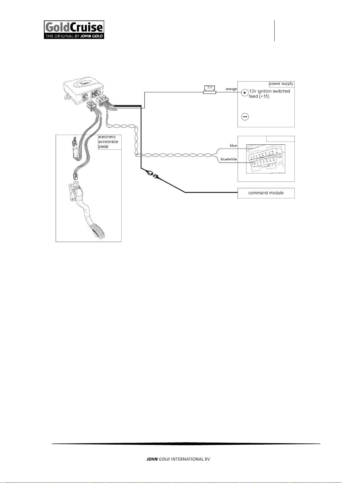
3.2 Wiring Diagram.......................................................................................................7
3.3 T-harness connection .............................................................................................8
3.4 Wiring harness connections ...................................................................................8
4Set-up..........................................................................................................................10
4.1 Introduction set-up...............................................................................................10
4.2 Release procedure................................................................................................11
4.3 The CG90Ci accelerator pedal set-up ...................................................................12
4.4 The CG90Ci vehicle speed signal set-up ...............................................................13
4.5 Testdrive ...............................................................................................................14
4.6 Increase response time ........................................................................................15
4.7 Reduce response time ..........................................................................................16
4.8 Increase sensitivity ...............................................................................................17
4.9 Reduce sensitivity .................................................................................................18
5Diagnostics and trouble shoot....................................................................................19
5.1 Diagnostics 1: CM, brake signal, clutch signal ......................................................19
5.2 Diagnostics 2:Accelerator pedal control, vehicle speed signal ............................20
5.3 Trouble shoot 1.....................................................................................................21
5.4 Trouble shoot 2.....................................................................................................21
5.5 Trouble shoot 3.....................................................................................................21
6Frequently Asked Questions.......................................................................................22

CAN-bus Cruisecontrol GC90Ci installation manual
3
1Purpose, construction and operation of the GC90Ci
1.1 Purpose of the GC90Ci
The purpose of the GC90Ci is to automate your speed management.
1.2 Construction
The GC90Ci is part of a Cruisecontrol-kit that consists of:
universal components:
electronic module (EM);
command module (CM) (order separately);
universal wiring harness;
general installation manual;
user manual CM (included with CM);
installation manual CM (included with CM);
programmer (available by download, ask your supplier);
programming harness (order separately);
installation manual programmer (available by download, ask your supplier).
specific components:
specific T-harness (order separately);
specific installation manual T-harness (supplied separately or by download,
depending on delivery option).
Depending on the modular supplies or the vehicle, more or less components are
applicable. Contact your supplier for more information.
1.3 Operation
The GC90Ci GoldCruise consists of a compact EM, that’s connected between the
electronic accelerator pedal and the engine-control–unit (ECU) of the vehicle.
The EM “manipulates” the ECU and controls the relationship between the driving speed,
throttle valve position and fuel injection time. The manipulation occurs by varying the
output signals of the accelerator pedal. This means that the signal structure in the ECU is
not altered at all. Because the accelerator pedal is learnt to the system, the GC90Ci
GoldCruise or speed limiter can make optimal use of the available engine power.

CAN-bus Cruisecontrol GC90Ci installation manual
4
2Safety directions
To ensure safety the GC90Ci complies with the following labels.
For the GC90Ci the following safety instructions apply, also printed in the item it
concerns:
Only use the GC90Ci for the purpose as described in this installation manual
The installer of the GC90Ci should have technical knowledge of modern cars
and be experienced in working on them
Incorrect and/or ignorant installation, connection, adjustments and/or
diagnostics can lead to vehicle and/or GC90Ci malfunctions
and indirectly affect road safety
Never alter or manipulate a GC90Ci. Alterations or technical manipulations
made to the GoldCruise products can affect its safety adversely

CAN-bus Cruisecontrol GC90Ci installation manual
5
Always solder the connections and insulate them with vulcanizing tape
Always install the EM in a position where heat, vibration and moisture are
minimized, such as underneath the dashboard
Undo the negative battery terminal before working on the vehicle.
Loss of volatile data is possible (audio, board computer, clock, etc.)
Always use a multimeter when measuring on the vehicle
Cut wires to size, keep them as short as possible
CAN-wires are twisted to assure a reliable operation. Make sure that the
twisting remains the same when the CAN-wires are shortened or extended
As the GC90Ci is supplied model specific, it is not necessary to learn the
accelerator pedal and speed signal. The GC90Ci will operate directly after
installation, unless indicated otherwise when the unit was programmed

CAN-bus Cruisecontrol GC90Ci installation manual
6
3Installation and connections
3.1 Installation electronic module (EM)
Always install the EM in a position where heat, vibration and moisture are minimized,
such as underneath the dashboard, never in the engine compartment.
The installation kit contains tie-wraps, double-sided tape and screws that can be used to
install the EM.
Always install the EM in a position where heat, vibration and moisture are
minimized, such as underneath the dashboard

CAN-bus Cruisecontrol GC90Ci installation manual
7
3.2 Wiring Diagram
OBD connector

CAN-bus Cruisecontrol GC90Ci installation manual
8
3.3 T-harness connection
Undo the negative battery terminal before working on the vehicle.
Loss of volatile data is possible (audio, board computer, clock, etc.)
As the T-harness is model specific, it is supplied as a separate component.
Read the accompanying installation manual carefully.
Connect the T-harness as follows:
Connect the 8-pin black connector of the T-harness to the 8-pin connector on the
EM;
Undo the accelerator pedal connector and connect it to the T-harness;
Connect the T-harness connector to the accelerator pedal.
3.4 Wiring harness connections
Always use a multimeter when measuring on the vehicle
Cut wires to size, keep them as short as possible
CAN-wires are twisted to assure a reliable operation. Make sure that the
twisting remains the same when the CAN-wires are shortened or extended
As the GC90Ci is supplied model specific. Connect the wiring harness as instructed in the
supplied specific installation manual.
Connect the universal wiring harness as follows:
orange wire
connect to an ignition switched feed (+15), preferably directly after
the ignition switch
blue wire
(twisted pair)
connect to CAN high
blue/white
wire
(twisted pair)
connect to CAN low
8-pin connector
Connect to the 8-pin connector of the CM, also refer to the
installation manual CM
4-pin connector
do not use

CAN-bus Cruisecontrol GC90Ci installation manual
9
Before using the ML90Ci Multi limiter should be released. Hereby the
ML90Ci checks or the CAN-bus signal for the brake is stable
As the GC90Ci is supplied model specific, it is not necessary to learn the
accelerator pedal and speed signal. The GC90Ci will operate directly after
installation, unless indicated otherwise when the unit was programmed
i
Re-connect the negative battery terminal and remember to set the lost
volatile data (audio, board computer, clock, etc.)

CAN-bus Cruisecontrol GC90Ci installation manual
10
4Set-up
4.1 Introduction set-up
These symbols are used for the command module:
i
action
symbol
function
up
SET /ACC
down
RES/DEC
push
ON/OFF
pull
CANCEL
The GC90Ci is supplied make/modelspecific with carefully selected settings. Yet there is
the possibility that the chosen settings are different than the required settings.
In that case it is possible to learn the accelerator pedal and speed signal manually:
refer to § 4.2 The CG90Ci accelerator pedal set-up
refer to § 4.3 The GC90Ci vehicle speed signal set-up
Check during the test drive (§ 4.4) the response time and sensitivity of the cruise control.
Only adjust the response time if the Cruisecontrol engages too slowly or too
aggressively:
refer to § 4.5 Increase response time
refer to § 4.6 Reduce response time
Only adjust the sensitivity if the Cruisecontrol reacts too forcefully or too slowly while
cruising:
refer to § 4.7 Increase sensitivity
refer to § 4.8 Reduce sensitivity

CAN-bus Cruisecontrol GC90Ci installation manual
11
4.2 Release procedure
The GC90Ci is secured with an release procedure, this procedure checks if there is a
proper CAN-bus brake signal available and properly programmed. The Cruisecontrol
askes you with beep-signals to press and release the brake pedal. This procedure needs
to be performed once after installation.
Read this procedure carefully before performing it.
Step
Action
Confirmation
1
Switch the ignition OFF and ON (do not start!)
2
Switch the Cruisecontrol ON
2 beeps low
3
Operate and holt it during step 4
Immediately after step 4, there are 3 long beeps audible perform then the following
action:
Beep audible Press the brake
Beep stops Release the brake, do this with all 3 beeps
4
Press the brake pedal 4 times and release
4 beeps
Immediately after step 4 the beeps starts
3 long beeps
5
Beep: Press the brake
CM-LED orange
6
Beep stops: Release the brake
CM-LED green
The Cruisecontrol is released:
4 beeps
The Cruisecontrol isn’t released:
4 high-low beeps
When the Cruisecontrol isn’t released, do step 1-6 again before contacting your
supplier
When this release procedure isn’t done correctly, the Cruisecontrol doesn’t operate, it is
however possible to:
-Learn the accelerator, learn the speed signal (not necessary with GC90Ci)
-Do the self-diagnostic
-Use the speed limiter (when programmed)

CAN-bus Cruisecontrol GC90Ci installation manual
12
4.3 The CG90Ci accelerator pedal set-up
This step is only necessary in case the programmed settings of the GC90Ci do not match
the required settings.
Perform the following steps to learn the GC90Ci to the accelerator pedal.
Perform step 1-6 within 1 minute!
Step
Action
Confirmation
1
switch the ignition OFF and ON (do not start!)
2
Switch the Cruisecontrol on
2 low beeps
3
Press and hold the brake pedal during the next 2 steps
4
Operate 4 times
4 beeps
5
Operate once
1 beep
6
Release the brake pedal
1 beep
7
Operate once
1 beep
8
Gently press the accelerator to full throttle
9
Operate once
beeps pulsating low
10
release the accelerator pedal
11
Press and hold the brake pedal and operate 4 times
beeps stop
1 long beep
12
Release the brake pedal
i
Some accelerator pedals do not have consistent signal values near the full
travel area (presence of a full throttle switch). Therefore the pedal set-up
may fail.
If at step 9 the beep pulsates high/low the pedal set-up failed.
In this case repeat the pedal set-up, but only press the accelerator pedal to
95% of its full travel at step 8

CAN-bus Cruisecontrol GC90Ci installation manual
13
4.4 The CG90Ci vehicle speed signal set-up
This step is only necessary in case the programmed settings of the GC90Ci do not match
the required settings.
Perform the following to learn the GC90Ci to the vehicle speed signal.
Perform step 1-7 within 1 minute!
Step
Action
Confirmation
1
Switch the ignition OFF and ON
2
Start the engine
3
Switch the Cruisecontrol ON
2 low beeps
4
Press and hold the brake pedal during the next 2 steps
5
Operate 4 times
4 beeps
6
Operate twice
2 beeps
7
Release the brake pedal
2 beeps
8
Drive at least 72 km/h (45 mph) and operate once
Cruisecontrol
engages, 1 beep
9
Press the brake pedal once.
2 beeps,
Cruisecontrol
releases
10
Stop in a safe place
11
Press and hold the brake pedal and operate 4 times
1 long beep
12
Release the brake pedal
i
Perform diagnostics if the Cruisecontrol does not engage at step 8. Refer to
chapter 5.0 Diagnostics and trouble shoot

CAN-bus Cruisecontrol GC90Ci installation manual
14
4.5 Testdrive
Step
Action
Confirmation
1
Switch the ignition OFF and ON
2
Start the engine
3
Switch the Cruisecontrol ON
2 low beeps
4
Drive 90 km/h (55 mph) on the highway and
operate
Cruise control engage and
maintains the speed
5
Press the brake pedal
Cruise control instantly
releases
6
Drive 75 km/h (45 mph) and operate once
(resume)
Cruise control engages and
accelerate exactly to last set
cruise speed (90 km/h(55
mph))
7
Operate long while cruising
Vehicle accelerates 10 km/h
(6 mph)
8
Operate long while cruising
Vehicle decelerates 10 km/h
(6 mph)
9
Operate 5x brief while cruising
Vehicle accelerates 5 km/h
(3 mph)
10
Operate 5x brief while cruising
Vehicle decelerates 5 km/h
(3 mph)
Only adjust the response time if the Cruisecontrol engages too slowly or too
aggressively:
refer to § 4.4 Increase response time
refer to § 4.5 Reduce response time
Only adjust the sensitivity if the Cruisecontrol reacts too forcefully or too slowly while
cruising:
refer to § 4.6 Increase sensitivity
refer to § 4.7 Reduce sensitivity
i
Perform diagnostics if the Cruisecontrol does not engage at step 8. Refer to
chapter 5.0 Diagnostics and trouble shoot

CAN-bus Cruisecontrol GC90Ci installation manual
15
4.6 Increase response time
Perform the following steps to increase the response time.
Perform step 1-7 within 1 minute!
Step
Action
Confirmation
1
Switch the ignition OFF and ON
2
Start the engine
3
Switch the Cruisecontrol ON
2 low beeps
4
Press and hold the brake pedal during the next 2 steps
5
Operate 4 times
4 beeps
6
Operate 3 times
3 beeps
7
Release the brake pedal
3 beeps
8
Drive at least 40 km/h (25 mph) and operate once
Cruisecontrol
engages
9
Operate until beeps are audible.
Number of
high beeps
10
Press the brake pedal once
3 beeps,
Cruisecontrol
releases
11
Drive at least 40 km/h (25 mph) and operate once
Cruisecontrol
engages
(determine the result. If necessary, repeat from step 9)
12
Stop in a safe place
13
Press and hold the brake pedal and operate 4 times
1 long beep
14
Release the brake pedal
lower
higher
step
beep
Operate 1x
for 1 step
Operate 1x
for 1 step

CAN-bus Cruisecontrol GC90Ci installation manual
16
4.7 Reduce response time
Perform the following steps to reduce the response time.
Perform step 1-7 within 1 minute!
Step
Action
Confirmation
1
Switch the ignition OFF and ON
2
Start the engine
3
Switch the Cruisecontrol ON
2 low beeps
4
Press and hold the brake pedal during the next 2 steps
5
Operate 4 times
4 beeps
6
Operate 3 times
3 beeps
7
Release the brake pedal
3 beeps
8
Drive at least 40 km/h (25 mph) and operate once
Cruisecontrol
engages
9
Operate until beeps are audible
Number of
low beeps
10
Press the brake pedal once
3 beeps,
Cruisecontrol
releases
11
Drive at least 40 km/h (25 mph) and operate once
Cruisecontrol
engages
(determine the result. If necessary, repeat from step 9)
12
Stop in a safe place
13
Press and hold the brake pedal and operate 4 times
1 long beep
14
Release the brake pedal
lower
higher
step
beep
Operate 1x
for 1 step
Operate 1x
for 1 step

CAN-bus Cruisecontrol GC90Ci installation manual
17
4.8 Increase sensitivity
Perform the following steps to increase the sensitivity.
Perform step 1-7 within 1 minute!
Step
Action
Confirmation
1
Switch the ignition OFF and ON
2
Start the engine
3
Switch the Cruisecontrol ON
2 beeps low
4
Press and hold the brake pedal during the next 2 steps
5
Operate 4 times
4 beeps
6
Operate 4 times
4 beeps
7
Release the brake pedal
4 beeps
8
Drive at least 40 km/h (25 mph) and operate once
Cruisecontrol
engages
9
Operate until beeps are audible
Number of
high beeps
10
Press the brake pedal once
4 beeps,
Cruisecontrol
releases
11
Drive at least 40 km/h (25 mph) and operate once
Cruisecontrol
engages
(Determine the result. If necessary, repeat from step 9)
12
Stop in a safe place
13
Press and hold the brake pedal and operate 4 times
1 long beep
14
Release the brake pedal
lower
higher
step
beep
Operate 1x
for 1 step
Operate 1x
for 1 step

CAN-bus Cruisecontrol GC90Ci installation manual
18
4.9 Reduce sensitivity
Perform the following steps to increase the sensitivity.
Perform step 1-7 within 1 minute!
Step
Action
Confirmation
1
Switch the ignition OFF and ON
2
Start the engine
3
Switch the Cruisecontrol ON
2 beeps low
4
Press and hold the brake pedal during the next 2 steps
5
Operate 4 times
4 beeps
6
Operate 4 times
4 beeps
7
Release the brake pedal
4 beeps
8
Drive at least 40 km/h (25 mph) and operate once
Cruisecontrol
engages
9
Operate until beeps are audible
Number of
low beeps
10
Press the brake pedal once
4 beeps,
Cruisecontrol
releases
11
Drive at least 40 km/h (25 mph) and operate once
Cruisecontrol
engages
(Determine the result. If necessary, repeat from step 9)
12
Stop in a safe place
13
Press and hold the brake pedal and operate 4 times
1 long beep
14
Release the brake pedal
lower
higher
step
beep
Operate 1x
for 1 step
Operate 1x
for 1 step

CAN-bus Cruisecontrol GC90Ci installation manual
19
5Diagnostics and trouble shoot
5.1 Diagnostics 1: CM, brake signal, clutch signal
Step
Action
Confirmation
1
Switch the ignition completely OFF
2
Operate and hold
3
Switch the ignition ON and wait for beeps
Beeps pulsating
4
Release
5
Switch the cruisecontrol ON
1 beep and CM-LED
turns green
6
Operate
1 beep and CM-LED
turns orange
(Does not operate: refer to § 5.3 trouble shoot 1)
7
Press the brake pedal briefly
1 beep and CM-LED
turns green
(Does not operate: refer to § 5.5 trouble shoot 3)
8
Operate
1 beep and CM-LED
turns orange
(Does not operate: refer to § 5.3 trouble shoot 1)
9
press the clutch pedal (only if a clutch protection is
installed)(does not operate: Refer to § 3.4 Wiring
harness connections)
or operate II.
(does not operate: refer to § 5.4 trouble shoot 2)
or press the brake pedal briefly
(does not operate: refer to § 5.5 trouble shoot 3)
possible beeps and
CM-LED turns green
10
if all operates well, refer to:
§ 5.2 Diagnostics 2: accelerator pedal control, vehicle
speed signal
11
Switch the ignition completely OFF to exit Diagnostics
Table of contents
Popular Automobile Electronic manuals by other brands

Chrysler
Chrysler MOPAR 82213929 Installation instruction

Sirius Satellite Radio
Sirius Satellite Radio SiriusConnect SNYSC1 Installation and user guide

Advent
Advent RVM740 user manual

CrimeStopper
CrimeStopper BackStopper CA-5005 install guide

FRC
FRC inView 360 Fusion installation guide

SVC GROUP
SVC GROUP FR-070-B1 Fitting instructions