Blue Ox BX8848 User manual

BX8848 Installation Instructions
4 Diode Wiring Kit
For Motorhomes With Red Tail Lights
292-1305 Rev. D Page 1 of 5 4/11/12
WARNING: Incorrect wiring may result in blown fuses, damaged wiring, re, or bodily injury. Blue Ox
recommends installation of this kit by a trained professional. Blue Ox will not be responsible for any
personal property damage, or bodily injury caused by incorrect wiring or misuse of this product.
Note: Some motorhomes may have amber turn signals and red brake lights. Check the rear outlet
to see if the turn and brake signals are on one pin or spade. If they are not a converter is required to
change from a 5 wire to a 4 wire system.
1. Starting in the engine compartment of the towed vehicle, run the harness through the re wall, under the
drivers side door sill plate, under the back seat, and into the trunk area. Depending on the motorhome set
up, the wire at the front of the engine compartment should be wired into either a 4-wire or 6-wire trailer plug
that is mounted to the front of the towed vehicle.
2. Make sure that the white wire is grounded to the vehicle chassis. It is also important to have a good ground
on the towing vehicle.
Use a 12 Volt D.C. continuity lamp tester with a needle point prod to identify the “hot” wires which power
the brake and tail lights. Ground one end of tester, and insert prod through the insulation of each wire
to identify. At this point the 4-conductor cable should be cut to length, leaving enough slack to reach the
tail light connector. NOTE: Vehicle lights must be on and the corresponding turn signals will have to be
operating in order for wires to be “hot”.
3. After the tail light and turn signal wires are identied and marked, shut off the power then cut each wire.
Cut any excess wire off of the four wire harness. Leave about 6 to 8 inches of slack. Separate the four
wires. Start on the outside and carefully peel each wire back about 6 inches. Cut and strip each wire and
crimp a female spade terminal on each wire. Plug the green wire into the right brake diode block. Plug
the yellow wire into the left brake diode block. Plug the female terminal from the front of the car into the
“in” side of the tail light diode blocks and the female terminal from the rear of the car into the “out” side of
the diodes. Plug the brown wire from the four wire harness into the “in” side of the diode block (see wiring
diagram). Test the car tail lights to make sure they work.
4. The last part of the wiring is to ground the four wire harness. The white wire is the ground. In the engine
compartment nd a bolt near the wire harness that will provide a metal-to-metal contact. Carefully cut just
the white wire and peel back enough wire to reach the selected bolt. Strip and crimp the ring terminal on
the wire. Remove the bolt and place the ring terminal under it and tighten. NOTE: If you are installing a
4-wire or 6-wire trailer plug on the front of the towed vehicle, then you may insert the ground into one of
these terminals to provide a ground for the system.
5. Secure the four wire harness several places between the grill and the front of dash to keep the harness
from getting tangled up in moving parts or touching engine parts that will get hot.
6. Hook up the towing vehicle to the wire harness and test the installation by operating the tail lights, turn
signals and brake lights. If the wiring on the towing vehicle does not match, you will need to change either
the wires at trailer plug or on the towing vehicle to match.

BX8848 Installation Instructions
4 Diode Wiring Kit
For Motorhomes With Red Tail Lights
292-1305 Rev. D Page 2 of 5 4/11/12
Tools Required
Electrical Tape Screwdriver Wire Cutter
Wire Striper Terminal Crimper Utility Knife
12 Volt DC Continuity Tester with needle point prod 5’ Stiff Pull Wire
EXISTING TOWED
RIGHT TAIL
LEFT TAIL
RIGHT BRAKE
GROUND (white)
TAIL LIGHT (brown)
RIGHT TURN/BRAKE (green)
MODULES
IN
IN
IN
IN
OUT
OUT
DIODE
LEFT
TURN/BRAKE
RIGHT
TURN/BRAKE
TAIL LEFT
VEHICLE WIRING
TORECEPTACLE
ON FRONT OF TOWED VEHICLE
LEFT TURN/BRAKE (yellow)
LEFT BRAKE
IN
IN
IN
IN
OUT
OUT
TAILRIGHT
Parts List
Ref. No. Qty. Part # Description
1 4 294-0660 Diode Module, 6 Amp
2 1 294-0562 Wire Harness, 26’, 4-Way Male
3 1 294-0187 Ring Terminal, 5/16 STD., 16-14 GA
4 12 294-0398 Terminal Coupling, Female, 22-18 GA
5 36” 194-0125 Wire, 14 GA. White

BX8848 Installation Instructions
4 Diode Wiring Kit
For Motorhomes With Amber Turn Signals
292-1305 Rev. D Page 3 of 5 4/11/12
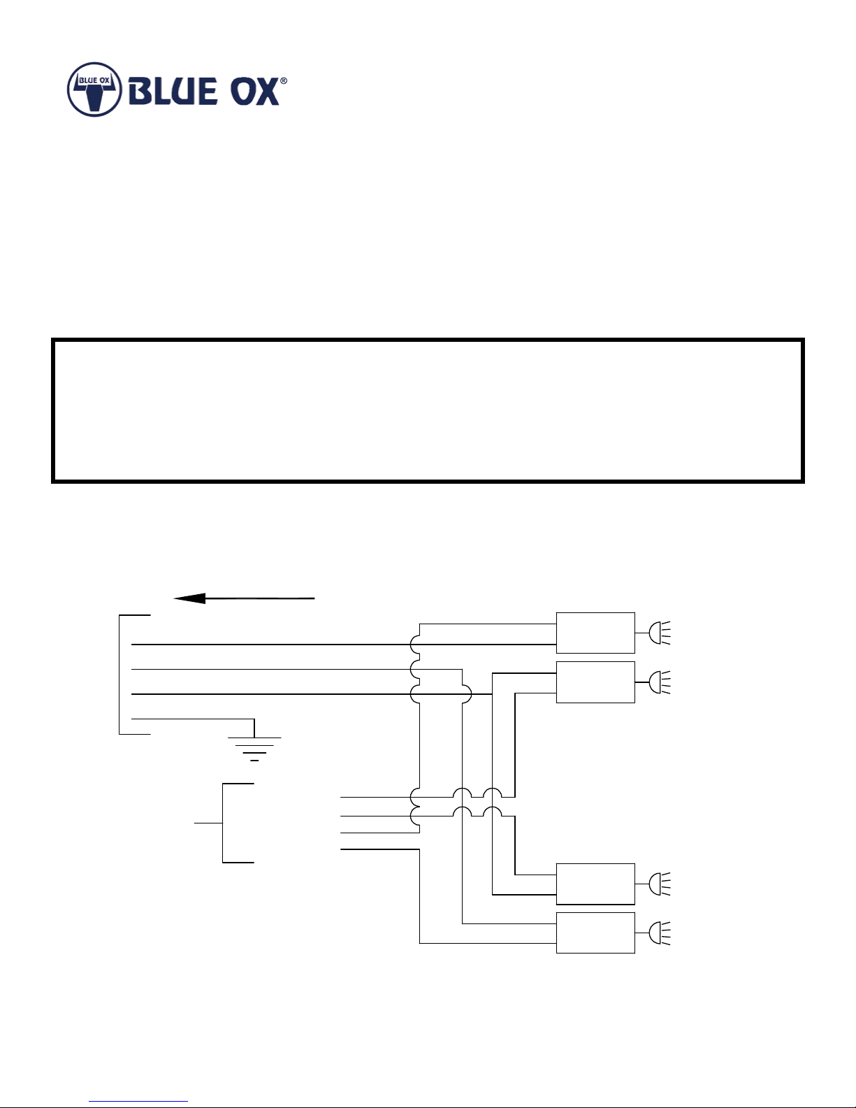
Overview: Run the four wire harness from the front of the car to the back seat of the car. Identify the proper wires on the
car wire harness under the back seat and splice in the diode modules. Hook the four wire harness into the diodes.
1. Decide where you want the plug of the wiring kit harness to stick out of the front of the car. This will be hooked/
unhooked each time you hook/unhook your tow bar, so nd a place that is convenient for you. The four wire plug will
need to be cut off and the six pin trailer plug substituted. Mounts for the trailer plug are not provided. A metal bracket
could be attached to the baseplate or a hole could be drilled in the bumper cover and the plug bolted into the cover.
2. On the driver’s side of the re wall there is a large rubber grommet where the main wire harness enters the passenger
compartment. The wiring kit harness will also enter the passenger compartment through this grommet. The grommet
is located directly behind the steering wheel and dash in the passenger compartment.
3. Route the wiring from the plug location back to the grommet in the re wall. Be sure to keep the wire away from
moving parts and areas that will get hot while the car is running.
4. Using a utility knife or a sharp pocket knife, cut a slit in the grommet just big enough to push the end of the wire
through into the passenger compartment. The smaller the slit the better, so don’t make it any bigger than needed.
5. Push about 12” of wire through into the passenger compartment. Locate the wire behind the dash and pull the rest
of the wire through into the passenger compartment, leaving plenty of slack in the engine compartment to tie the wire
harness down and still leave the plug in the desired position.
6. Along the threshold of the driver’s side door there is a piece of plastic that holds the carpet down. The plastic snaps
into the metal frame. Starting near the center post, pull up the plastic and unsnap it from the metal frame. The plastic
narrows and continues up around the door. Do not pull this part of the plastic loose.
7. The carpet ends behind and above the brake pedal. Feed the wire harness behind the carpet and down to the
threshold of the door. Pull all the wire down to this point. Lay the wire under the carpet back to the center post.
8. The bottom of the back seat is held down by two steel clips. The clips are located along the front of the seat and
would be between your legs if you were sitting in the seat. Slide your nger or a small screwdriver along the seam
between the seat and the oor to locate the exact position. To release the clip push in on the clip with a screwdriver.
With both clips released, pull the front of the seat up and remove the seat.
9. The back door threshold is similar to the front. Pull up the threshold to gain access under the carpet. Run the wire
harness around the center post (you may need a piece of stiff wire to help push the wire through) and along the back
door and into the back seat area. Replace the carpet and thresholds.
10. Under the driver’s side of the back seat there is a plastic loom. Open the loom and pull out the wires. You will nd
several light blue colored wires. Some of these wires are used for the left, right, and center brake lights. Have
someone step on the brakes and use a needle point tester to determine which wires are used for the brakes. The
others may be “hot” when the stereo is on, so the stereo system must be shut off while you are identifying wires.
11. When you have identied the brake wires, strip the ends and crimp on a male spade terminal on the end of the
wire from the front of the car and a female spade terminal on the end running to the back of the car. Plug the male
terminal into the “in” side of the diode block and the female terminal into the “out” side of the diode. Try the brakes to
make sure the lights work.
12. Cut any excess wire off of the four wire harness. Leave about 6 to 8 inches of slack. Separate the four wires. Start
on the outside and carefully peel each wire back about 6 inches. Inspect each wire to make sure there aren’t any
bare spots showing. Wrap any bare spots with electrical tape. Strip each wire and crimp a male spade terminal on
each wire. Plug the white wire into the brake diode block.

BX8848 Installation Instructions
4 Diode Wiring Kit
For Motorhomes With Amber Turn Signals
292-1305 Rev. D Page 4 of 5 4/11/12
13. There are several brown wires in the loom. Depending on your model, 2 to 4 are used for the tail lights. Turn on the
tail lights and use the needle point tester to identify the tail light wires. (Remember, stereo must be off.) When all are
identied, cut the wires, strip them, and twist them together. Crimp a male spade terminal on the wires from the front
of the car and a female spade terminal on the wires going to the tail lights. Plug the male terminal into the “in” side of
a diode block and plug the female terminal into the “out” side of the diode block.
14. Plug the brown wire from the four wire harness into the “in” side of the diode block. Test the car tail lights to make
sure they work.
15. There are multiple yellow wires in the loom. One of them is the left turn signal. Use the needle point tester to nd the
correct wire. When you have the correct wire, cut it , strip the ends, and put a male terminal on the wire from the front
and a female terminal on the wire going to the turn light. Plug the male terminal into the “in” side of a diode block and
the female terminal into the “out” side. Plug the yellow wire from the four wire harness into the remaining terminal on
the diode block.
16. The dark green wire in the loom is the right turn signal. Use the needle point tester to verify that you have the correct
wire. When you have the correct wire, cut it , strip the ends, and put a male terminal on the wire from the front and
a female terminal on the wire going to the turn light. Plug the male terminal into the “in” side of the fourth diode
block and the female terminal into the “out” side of the diode. Plug the green wire from the four wire harness into the
remaining terminal on the diode block.
17. Test the turn signals to make sure they work.
18. The last part of the wiring is to ground the harness. A 36” piece of white wire has been supplied as the ground wire.
In the engine compartment nd a bolt that will provide a metal-to-metal contact. Strip and crimp the ring terminal on
one end of the wire. Remove the bolt and place the ring terminal under it and tighten. Run the other end of the wire
out to the grill by the four wire harness.
19. Using the cable ties provided, secure the four wire harness several places between the grill and the rewall to keep
the harness from getting tangled up in moving parts or touching parts that will get hot.
20. The last thing to wire is the 6 pin trailer plug. If your motorhome already has a plug on it, identify which pins are what
on that plug and match the wires to the pins as you wire the plug on the car. You can also go ahead and wire the plug
and make adjustments for mismatched wires by switching wires where they plug into the diodes.
21. Hook up the towing vehicle to the wire harness and test the installation by operating the tail lights, turn signals, and
brake lights. If the wiring on the towing vehicle does not match, you will need to change either the wires in the back
seat or on the towing vehicle to match.
22. When the installation is working properly, replace as many wires as possible back into the plastic loom in the back
seat. Use electrical tape to secure the rest of the wires together. Lay the diode blocks and wiring as at as possible
against the oor under the seat. Replace the rear seat. Feed all the seat belt straps and buckles through the holes in
the seat as you replace it.

BX8848 Installation Instructions
4 Diode Wiring Kit
For Motorhomes With Amber Turn Signals
292-1305 Rev. D Page 5 of 5 4/11/12
Tools Required
Electrical Tape Screwdriver Wire Cutter
Wire Striper Terminal Crimper Utility Knife
12 Volt DC Continuity Tester with needle point prod 5’ Stiff Pull Wire
Parts List
Ref. No. Qty. Part # Description
1 4 294-0660 Diode Module, 6 Amp
2 1 294-0562 Wire Harness, 26’, 4-Way Male
3 1 294-0187 Ring Terminal, 5/16 STD., 16-14 GA
4 12 294-0398 Terminal Coupling, Female, 22-18 GA
5 36” 194-0125 Wire, 14 GA. White
SATURN WIRING
OUT
IN
BRAKES (Light Blue)
LEFT TURN (Yellow)
TAIL LIGHT (Brown)
RIGHT TURN (Dark Green)
IN
IN OUT
IN
IN
IN
IN
IN
OUT
OUT
MODULES
DIODE
AMBER LEFT
TURN
RIGHT
BRAKE
AMBER RIGHT
TURN
LIGHTS
TAIL
LEFT
BRAKE
GROUND
Dark
Green
Brown
LtBlue
Yellow
GROUND
Supplied White Wire
BRAKES - White
LEFT TURN -Yellow
TAIL LIGHT - Brown
RIGHT TURN - Green
NOT USED
BRAKE LIGHT
LEFT TURN
TAIL LIGHT
RIGHT TURN
NOT USED
MOTORHOME
6 Pin Trailer Plug
1 Pin Not Used
Female HalfOnly
Supplied With Kit
© 2012 Blue Ox
One Mill Road, Industrial Park
Pender, Nebraska 68047
Phone: (402) 385-3051 • Fax: (402) 385-3360
www.blueox.com
Table of contents
Popular Automobile Electronic manuals by other brands

Subaru
Subaru Consumer Electronics/ Bluetooth & Audio Technology... Quick reference guide

iDataLink
iDataLink ADS-TBSL-GM install guide

HaWeKo
HaWeKo HYK280 installation manual

BrandMotion
BrandMotion 5000-CA14 installation instructions

Metra Electronics
Metra Electronics 99-5825S installation instructions

iDataLink
iDataLink maestro Rr ADS-RR-FOR01-DS-IG-EN install guide

Sunshine Technology
Sunshine Technology C53 quick start guide

VDO
VDO OPERATING HOURS COUNTER installation instructions

Master Tailgaters
Master Tailgaters MR-43-H2 user manual

Connects2
Connects2 CAM-KIT15 user manual

CrimeStopper
CrimeStopper BackStopper CA-5005 install guide

USA SPECS
USA SPECS PA15-TOY owner's manual