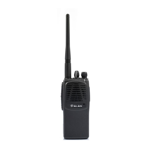
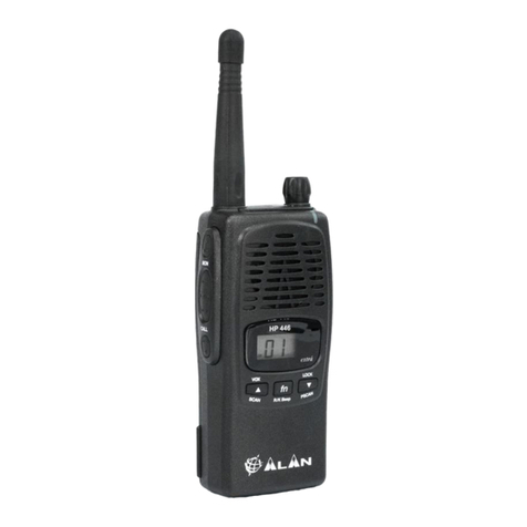
Alan HP106 User manual

ALAN HP 106
SERVICE MANUAL

HP106 Service Manual
Page 1 of 12
ALAN HP106
Portable VHF Transceiver
Service Manual
Copyright 2003 by CTE International Italy; all rights reserved

HP106 Service Manual
Page 2 of 12
Contents
1TECHNICAL SPECIFICATIONS......................................................................................................................3
1.1 Test methods.................................................................................................................................................................3
1.2 Specifications table .......................................................................................................................................................3
2CIRCUIT DESCRIPTION .................................................................................................................................4
2.1 General information.......................................................................................................................................................4
2.2 Microprocessor/control ..................................................................................................................................................4
2.3 VCO / Synthesizer (PLL) ...............................................................................................................................................4
2.3.a Temperature-Compensated Crystal Oscillator (TCXO) ..................................................................................................... 4
2.3.b Voltage-Controlled Oscillators ........................................................................................................................................... 4
2.3.c Synthesizer ........................................................................................................................................................................... 5
2.3.d Loop Filter ........................................................................................................................................................................... 5
2.4 Transmitter ....................................................................................................................................................................5
2.4.a RF Power Amplifier ............................................................................................................................................................. 5
2.4.b Antenna Switching ............................................................................................................................................................... 5
2.4.c Power control....................................................................................................................................................................... 6
2.4.d Transmitter Audio Circuits .................................................................................................................................................. 6
2.4.e Audio Processing ................................................................................................................................................................. 6
2.5 Receiver ........................................................................................................................................................................6
2.5.a Receiver Front End .............................................................................................................................................................. 6
2.5.b Local Oscillator (LO) .......................................................................................................................................................... 6
2.5.c Mixer .................................................................................................................................................................................... 6
2.5.d FM Detector and Squelch .................................................................................................................................................... 6
2.5.e Receiver Audio Circuit......................................................................................................................................................... 7
2.6 Signalling.......................................................................................................................................................................7
2.6.a General................................................................................................................................................................................. 7
2.6.b CTCSS Tone Encoder / Digital Code Squelch (DCS) Encoder .......................................................................................... 7
2.6.c Selective call ........................................................................................................................................................................ 7
2.6.d Scrambler ............................................................................................................................................................................. 7
2.7 Battery ...........................................................................................................................................................................7
3ADJUSTMENTS ..............................................................................................................................................9
3.1 General..........................................................................................................................................................................9
3.2 Synthesizer/Transmitter VCO Check ............................................................................................................................9
3.2.a Frequency Adjustment ......................................................................................................................................................... 9
3.3 Transmitter Alignment ...................................................................................................................................................9
3.3.a Power Adjustment ................................................................................................................................................................ 9
3.3.b Modulation Adjustment........................................................................................................................................................ 9
3.3.c CTCSS/DCS adjustment..................................................................................................................................................... 10
3.3.d Selcal adjustment ............................................................................................................................................................... 10
3.4 Receiver Alignment .....................................................................................................................................................10
3.5 Figure 1 - Equipment Test set-up................................................................................................................................11
3.6 Figure 2 - Test adaptor................................................................................................................................................12

HP106 Service Manual
Page 3 of 12
1 TECHNICAL SPECIFICATIONS
1.1 Test methods
ETS 300-086
IEC 529 IP54 and MIL STD 810 C/D/E
1.2 Specifications table
General
Characteristic Units Value/Measurements conditions
Frequency MHz from 148 to 174
Operating Band MHz 26
Number of Programmable Channels - 16
Channel Spacing KHz 12.5 / 20 / 25
Frequency Steps KHz 5 / 6.25
Rated Power Supply Vcc 7.5
Battery Capacity mAh Ni-MH 1.300
5% on TX at the maximum power
5% on RX at 60 % of the maximum rated A.F. power
Duty Cycle hours
90% on RX with closed squelch in power save mode
8
Antenna Impedance Ohm 50
Speaker Impedance Ohm 8
Frequency Stability ppm ±2.5
Operating Temperature Range °C from –30 to +60
Transmitter
Output Power (±1 dB) W 1 / 5
from 9 KHz to 1 GHz < 0,25Spurious Emissions µW
from 1 to 4 GHz < 1
Modulation System - F3E (FM)
Modulation KHz
±2,5 / 5
Audio Distortion - 5 % or less
Maximum Deviation KHz ±2.5 / 5
Adjacent Channel Power Attenuation dB < -60 / -70
Receiver
Configuration Double Conversion Superetherodyne
Sensitivity (at 12 dB SINAD) µV < 0.35
Squelch Sensitivity (SINAD) dB 10
Selectivity (Adjacent Channel) dB At least -65 / -75
Spurious Response Rejection dB > 70
Intermodulation dB > 65
Hum & Noise Suppression dB < -45 / < -40
Audio Output (1 KHz at 5% T.H.D.) mW 400
Mechanical Specifications
Size (Battery Pack Included) mm 130 x 42 x 60
Weight (Battery Pack Included) g 355
Battery - Back slide battery
Accessories Connector / Programming - 2.5 and 3.5 mm standard monophonic jacks
Moisture & Dust Resistance - According to the IEC529 and IP54 regulations

HP106 Service Manual
Page 4 of 12
2 CIRCUIT DESCRIPTION
2.1 General information
The HP-106 has three printed circuit boards. Circuitry is divided in the following sections:
Microprocessor/Control
VCO/Synthesizer
Transmitter
Receiver
Signalling
Battery
Refer to the Block Diagram and the Schematics.
2.2 Microprocessor/control
The microprocessor IQ9 is constantly operating when the radio is turned ON. It is continuously monitoring the
keyboard, the PTT line and other internal inputs such as the squelch detect, etc. When a change occurs, the
microprocessor makes the appropriate response. The microprocessor is used for control. The Radio emits a beep
on channel change and the synthesizer is loaded with the correct frequency information. The microprocessor runs
off a 8 MHz oscillator which is composed of IX1, IC30, IC31 and IR48.
When the radio is first turned on, the microprocessor reads the radio status from the EEPROM IQ8.
The microprocessor determines the receive frequency codes, then loads the synthesizer via its pins 42 (PLL LE),
46 (PLL CLK) and 43 (PLL DATA).
The microprocessor is fitted with an internal program flash memory as well, therefore functions can be
customised, if necessary, upon specific request from the customer.
2.3 VCO / Synthesizer (PLL)
This section consists of the Temperature-Compensated Crystal Oscillator (TCXO), Voltage Controlled
Oscillator(VCO), Synthesizer and the Loop Filter.
2.3.a Temperature-Compensated Crystal Oscillator (TCXO)
The reference oscillator (X401) is a temperature compensated crystal- oscillator, RV402 is used to adjust the
oscillator on frequency (14.4 MHz) at room temperature (22 ℃). The reference oscillator is held within the
specified ±2.5 PPM from -30 to +60℃.
2.3.b Voltage-Controlled Oscillators
Only one of the VCOs runs at a time, which is controlled by Q420 and IQ9. When the PTT is pressed, IQ9 pin 34
goes low (approx. 0V) disabling the receive VCO by the Q420 and biases on Q419 to enable the transmitter VCO.
The receive VCO consists of C482-C485, CV401, L426-L428, and Q422-Q424. This VCO oscillates at 45.1 MHz
above the programmed receive frequency. The VCO’s oscillating frequency is tuned by the varactors Q423 and
Q424. The tuning voltage is supplied from the output of the Loop Filter. The output of the VCO is AC coupled
(C475 and R558, C530,C505) to the synthesizer and the output buffer Q414 respectively.
The transmitter VCO consists of C487, C489-C491, CV402, L424, L425, L429 and Q416-Q418.
This VCO oscillates on the programmed transmit frequency. The VCO’s oscillating frequency is tuned by the
varactors Q417 and Q418. The tuning voltage is supplied from the output of the Loop Filter. The output of the
VCO is AC coupled (C486) to the synthesizer input buffer Q428 and the output buffer Q415 respectively.
The transmit voltage controlled oscillator is directly frequency-modulated and operates on the carrier frequency. In
the receive mode, the transmit VCO is disabled and the receive VCO is enabled, producing the receive local
oscillator signal at a frequency 45.1 MHz below the incoming receive frequency.

HP106 Service Manual
Page 5 of 12
The synthesizer is tuned in 5.00 KHz or 6.25 KHz step.
2.3.c Synthesizer
The frequency synthesizer is a large scale monolithic synthesizer integrated circuit Q429.
The synthesizer IC contains a dual modular prescaler, programmable divide-by-N counter, prescaler control
(swallow) counter, reference oscillator, reference divider, phase detector, charge pump and lock detector.
Also, included in Q429 are shift registers and control circuits for frequency controls and general device control.
RF output from the active VCO is AC coupled to the synthesizer Q429 prescaler input at Pin 8. The divide-by-N
counter chain in Q429, consisting of the dual-modulus prescaler, swallow counter and programmable counter,
divides the VCO signal down to a frequency very close to 5.00 KHz or 6.25 KHz which is applied to the phase
detector. The phase comparator compares the edges of this of this signal with that of the 5.00 KHz or 6.25 KHz
reference signal from the reference divider and drives the external charge pump (Q425 and Q426).
The synthesizer unlock detector circuit prevents the operation of the transmitter, when the phase lock loop (PLL)
is unlocked. The following discussion assumes the unit has been placed in the transmit mode. Q429 lock detector
Pin 7goes high when the PLL is locked. This high level is applied to Pin 21 of the microprocessor IQ9. A software
timing routing brings the RX/TX line low (Pin 29 of IQ9), feeding this signal through the switch/buffer IQ15. With
the RX/TX line low, Q223A is cut off and Q223B is biases on passing +5VTX to Q431B, it biases on Q430 to pass
switched TX B+ to the transmitter amplifier string which enables transmission.
When the PLL become unlocked, the lock detector at Q429 Pin7 will begin pulsing low. A RC circuit converts
pulsing low to a low level for the microprocessor. The microprocessor then changes the RX/TX line to a high, thus
signalling the other transistor switches to drive Q430 into cutoff which disable transmission. Therefore, the
transmitter remains disabled while the loop remains out of lock.
2.3.d Loop Filter
The Loop Filter, a passive lead-lag filter consisting of R461-R464 and C493-C495, integrates the charge pump
output to produce the DC turning voltage for the VCO. One parasitic pole, consisting of R461/C493 and RF
chokes L428/L429, prevent modulation of the VCOs by the 5.00 KHz or 6.25 KHz reference energy remaining at
the output of the loop filter. Direct FM is obtained for modulating frequencies outside the PLL bandwidth by
applying the CTCSS/DCS signals and the pre-emphasized, limited microphone audio to the VCO modulation
circuit.
The modulation circuit consists of R452,Q421 and C487.
2.4 Transmitter
2.4.a RF Power Amplifier
After the PTT is pressed, the +5VTX line switches to approximately 5V. Q419 is turned on enabling transmit VCO.
The VCO buffer, pre-driver, driver and power amplifier are biased on by Q430, which is biased on by the +5VTX
line switching to 5V. RF output from the transmit VCO(Q416) is applied to the VCO output buffer Q415.
Output from Q415 feeds the pre-driver amplifier Q413. The output signal from Q413 feeds the driver amplifier
Q412, whose output from the driver stage feeds the final RF power amplifier Q407 to produce the rated output
power of 2 watts. The output of the final is applied to a low-pass filter(C451, C452 and L413) and then to the
transmit/receive switch Q402. RF power is then fed to the antenna via the output low-pass filter consisting of
C401,C403,C405-C408, L401, and L402.
2.4.b Antenna Switching
Switching of the antenna between the transmitter and the receiver is accomplished by the antenna
transmit/receive switch consisting of diodes Q401 and Q402 in conjunction with C410 and R402. In the transmit
mode, switched TX B+ is applied through R420 and RF choke L414,hard forward biasing the two diodes on. Q402
thus permits the flow of RF power from output of the low-pass filter fed by the output amplifier to the output low-
pass filter. Q401 shorts the receiver input to C410, which is AC coupled to ground. L403, C409, C410 and R402
then function as a lumped constant quarter-wave transmission line, thus presenting a high impedance to the RF
output path, effectively isolating the receiver input and transmitter output sections.

HP106 Service Manual
Page 6 of 12
2.4.c Power control
Output power is controlled via the dual Op-Amp (Q408) , which is used as a differential amplifier and comparator.
Current is sensed by the voltage drop across R421 and R422. This voltage is compared to the one set by the 2-
watt Adjustment RV401. The power output is then reduced or increased by varying the Q410's output voltage
applied to the power amplifier Q407's pin 2.
2.4.d Transmitter Audio Circuits
The transmitter audio circuits consist of the audio processing circuits, the CTCSS circuits and the DCS circuits.
2.4.e Audio Processing
Transmit speed audio is providing by either the internal electric microphone N101 or the external microphone. The
microphone audio is applied to MIC MUTE SW Q235, and Lo-pass filter Q214A, Q214B. The audio is pre -
emphasized by 6dB per octave by C236 and R284, and then signal amplification. The gain is such that when a
signal greater than 20 dB.
Limiting the peak-to-peak output. Under these conditions, the MOD. ADJ. Pot RV201 configured as a four-pole
active low-pass filter. The resulting signal is then limited when respect to side band splatter, and has an 18 dB per
octave roll-off above 3 KHz.
The audio is then applied through the 25 KHz/12.5 KHz channel spacing SW Q215 to transmit VCO. By varying
the voltage on the varactor diode Q921 at an audio rate. The resonant frequency of VCO is varied. The result is
an oscillator output that is frequency -modulated at the audio frequency.
2.5 Receiver
2.5.a Receiver Front End
In the receive mode, the RF signal enters thorough the antenna, then through the low-pass filter C401, C403,
C405-C409 and L401-L403. The diodes Q401 and Q402 are biased off so that the output of the low-pass filter is
coupled (C411) to the first band-pass filter C412-C415,C417-C420,L404-L407 and to the Front End RF overload
protection diode pair Q403. The signal from the band-pass filter is applied to the input of the RF amplifier Q404.
The output of the RF amplifier feeds the input to three more stages of band-pass filters consisting of C424-C431,
and L408-L410. The output from the band-pass filter is applied to the mixer’s Q405/L411.
2.5.b Local Oscillator (LO)
The Receive VCO (C482-C485, CV401, L426-L427, Q422-Q424 and R453-R454) provides the LO signal. The
VCO is running at 45.1 MHz above the desired receive frequency and is applied to output Buffer Q415/Q414. The
output of the buffer through the low-pass filter C433-C435, L432-L433 and applied to the mixer Q405/L411/L412.
2.5.c Mixer
The mixer is a DBM type (L411,Q405,L412). The mixer LO frequency is 45.1 MHz below the desired receiver
frequency.
When the receiver frequency is present, the mixer output will be a 45.1MHz signal. The mixer output is peaked for
45.1MHz at L434, C437 and R413, and the signal is filtered by crystal filter F401A and F401B and amplified by
Q406 before being applied to the input of the IF IC IC6.
Inside IC6, the 45.1MHz IF signal becomes the input to a second mixer with a LO frequency of 44.645 MHz set by
X201. The 455 KHz ceramic filter F201 or F202 filters the second mixer’s output which is the second IF signal.
The mixer’s output is then fed to the internal limiting amplifier and then on to the FM decoder.
2.5.d FM Detector and Squelch
The FM detector output is used for squelch, decoding tones and audio output. The setting of the squelch
adjustment potentiometer RV204 (for 25 KHz channel spacing) and RV205 (for 12.5 KHz channel spacing) sets
the input to the squelch amplifier.
The squelch amplifier is internal to IC6 and its output is fed to an internal rectifier and squelch detector.

HP106 Service Manual
Page 7 of 12
The output on IC6 Pin 14 signals the microprocessor IQ9 with a low level (~0V) to unmute the radio.
The audio is unmuted by the microprocessor IQ9 Pin 27 switching to a high value (~5V on SQL MUTE) thus
biasing on Q206. The audio is then routed to the audio amplifier Q221 via the volume control S201.
2.5.e Receiver Audio Circuit
The detector’s audio output also is fed to the tone(CTCSS and DCS) low-pass filter Q212C.
Then the output of the low-pass filter is routed to the second stage filter Q212B. The output of Q210B is applied to
the squaring circuit Q212A and finally to the microprocessor IQ9 Pin 60 for decoding.
Another branching of the detector output feeds the audio high-pass filter Q208 via Q212D. The output of the audio
high-pass filter feeds the Volume Control S201(VOL). From the wiper arm on the Volume Control, the audio is
routed to Pin 2, the input to the audio power amplifier Q221. The output of the audio power amplifier is routed
through the earphone jack J401 to the internal speaker E101.
2.6 Signalling
2.6.a General
The microprocessor is fitted with a ADC/DAC converter built-in, so it provides generating and decoding the tones
for selective calls, CTCSS and DCS. It can do that without using any other external ICs, but only by means of
some transistors. The deviation of the selective call can be adjusted by the trimmer IRV1.
The microprocessor manages the analogue switches for the scrambler as well, which is base-band-inversion type.
2.6.b CTCSS Tone Encoder / Digital Code Squelch (DCS) Encoder
CTCSS signals and DCS signals are synthesized by microprocessor IQ9 and appear as pulse waveform on I/O
line at Pin 39. This I/O line is a pseudo-sine wave for CTCSS or a DCS pseudo-waveform and is applied to the
transistor IQ5 which makes the signals closer to the theoretic CTCSS/DCS signals. The waveform is then
smoothed by low pass filters Q213B to produce an acceptable sine wave output. The CTCSS tone signal is adjust
to the proper level by RV202. The DCS signal is adjust to the proper balance by RV203. The signal is then applied
to the audio processing circuit at R305 and to the TCXO circuit at X401.
2.6.c Selective call
Similarly to CTCSS/DCS, selcal signals are also generated and decoded by the microprocessor IQ9. The selcal
decode input is the pin 59 (ADC_SELCALL), whilst the TX tones are generated at pin 37 (SELCALL_PWM), then
fed to the transistor IQ4 and associated circuitry which provides to amplify and smooth the tones in order to make
them suitable for the modulator. IRV1 adjusts the level (deviation) of the tones.
2.6.d Scrambler
It’s a classic “baseband inversion” scrambler which inverts the audio baseband (300-30000 Hz). The audio
baseband AFTX_IN is mixed with a fixed tone (1300 Hz) SCRMBLR_CLK generated by the microprocessor IQ9.
The mixer’s output AFTX_OUT is a scrambled baseband which sounds garbled (not understandable) by normal
receivers. However, if the receiver is equipped with the same kind of scrambler which is properly set on the same
fixed tone, the received scrambled baseband is fed in the RX mixer which provides a complementary process
obtaining a clear (understandable) baseband at its output. If fact if the scrambled transmission is received by the
party’s HPx06 (with scrambled activated), the scrambled baseband AFRX is fed to the scrambler unit and mixed
with the same tone generated by the microprocessor. The output of the mixer AFRX_OUT is a normal
(unscrambled) baseband and can be clearly heard.
As you can see, the over stated fixed audio tone acts as a encoding/decoding key, so it must be the same both at
the TX and RX parties. As already stated, the standard version of HPx06 is fitted with a 1300 Hz
encoding/decoding key, however a different tone can be required.
2.7 Battery
The battery connects to the contact pins(CN201 and CN202) on the bottom end of the Radio. The positive
terminal of the battery connects to the ON/OFF Volume Control switch (S201)and the negative terminal connects
to chassis ground. Low battery sense R101/R102, voltage regulator Q222 and transmit power module Q407.

HP106 Service Manual
Page 8 of 12
The battery voltage status is monitored by the microprocessor IQ9 Pin 61 which senses the battery voltage
through the BATT+SW line by means of IR51/IR49. When the battery voltage is approximately 5.8V, the
microprocessor considers the battery discharged and switches off the circuits of the radio.
When the Radio is on a channel with no tone programmed, the BATTERY SAVER Mode is enabled when
programmed.
In the BATTERY SAVER mode, the microprocessor IQ9 generates a square wave signal at Pin 48 which is
applied to the inverter IQ10:6. The signal’s duty cycle varies according to what the POWER SAVE TIMER is set.
When the microprocessor IQ9 Pin 48 goes high (approx. 5 V) Q226 (receiver module) is biased off, Q225 is
biased on, Q224A is cut off, and Q223A is cut off, thus turning the supply off to IC6.

HP106 Service Manual
Page 9 of 12
3 ADJUSTMENTS
3.1 General
For proper alignment, the unit should be programmed with the following channel and frequency information
Channel
number
Receive Frequency
(MHz)
Transmit Frequency
(MHz)
RX/TX Tone Code Channel Spacing
(KHz)
CH 1 174.050 174.025 NO TONE 25
CH 2 163.050 163.025 NO TONE 25
CH 3 163.050 163.050 100Hz TONE 25
CH 4 163.050 163.050 627 DCS CODE 25
CH 5 163.050 163.025 NO TONE 12.5
Make connections to the Unit per Figure 1 (Equipment Test Set-up) below and Figure 2 (Test Adapter). For the
location of the components called out in these procedures, refer to RF Board and SUB Board.
3.2 Synthesizer/Transmitter VCO Check
NOTE: VCO check must be accomplished before proceeding with the Transmitter and/or Receiver Alignment.
1) Connect the voltmeter to TP6.
2) Place the unit on channel 1 (174.050MHz. RX; 174.025MHz, TX).
3) Tune CV401 in Receive mode for 4.90V ± 0.05V at TP6.
4) Push the PTT switch (TX) and tune CV402 for 4.30V ± 0.05V at TP6.
3.2.a Frequency Adjustment
1) Connect the Radio in accordance with Figure 1.
2) Place the unit on channel 1 (174.050MHz, RX; 174.025MHz, TX).
3) Operate the transmitter and adjust RV402 for a Frequency Counter reading within ± 50Hz of the programmed transmit
frequency.
3.3 Transmitter Alignment
NOTE: In order to obtain proper transmission output power, connect the Radio to the power supply with a cable that is
rated to withstand a current of 2 amperes or greater.
3.3.a Power Adjustment
1) Connect the Radio in accordance with Figure 1.
2) Place the radio on the channel 2 (163.050MHz, RX; 163.025MHz. TX).
3) Place the unit in HIGH POWER mode.
4) Turn RV401 and RV405 fully clockwise.
5) Operate the transmitter, using TA-S1, to make sure that the maximum RF output power reading on the wattmeter is 5.5 W or
greater.
6) Adjust RV401 (HI PWR ADJ) for a reading of 5.0 W ±0.1 W. Check to make sure that the transmit current is within 1000 -
1400 mA after the adjustment has been made.
7) Place the unit in the LOW POWER mode.
8) Adjust RV405 (LO PWR ADJ) for a reading of 1.0 W ±0.1 W. Check to make sure that the transmit current is within 500 -
700 mA after the adjustment has been made.
3.3.b Modulation Adjustment
1) Connect the Radio in accordance with Figure 1.
2) Place the Radio on channel 2 (163.050MHz, RX; 163.025MHz, TX).
3) Apply a 1 KHz tone signal to Test Adapter's AF Input (Figure 2), which is the microphone impedance matching network.
4) Plug the Test Adapter into the external speaker/microphone jack.

HP106 Service Manual
Page 10 of 12
5) Set the audio generator's output level at approximate 300mVrms at TPA of the Test adapter.
6) Operate the transmitter, using TA-S1, and adjust RV201(MOD.ADJ) for ±4.0 KHz deviation.
3.3.c CTCSS/DCS adjustment
7) To adjust CTCSS and DCS Deviation, perform step1 though 6 above. Then set the FM liner detector audio bandwidth of
0.25 Hz or less to15,000 Hz or more. Turn the de-emphasis function off.
8) Place the Radio on channel 4 (163.050MHz. TX; 627 DCS CODE). Set the audio generator output to 0V operate the
transmitter, using TA-S1 and adjust the DCS balance control RV203 to U1-U2 is minimum on the Oscilloscope.
9) Place the Radio on channel 3 (163.050MHz, TX; 100Hz Tone). Operate the transmitter using TA-S1, and adjust RV202 to
±800Hz deviation on Modulation Analyzer.
3.3.d Selcal adjustment
10) Set up a selcall sequence which includes, at least, an hi-pitched tone and a tone length of 1 second minimum (in order to
allow a convenient deviation check)
11) Send the selcal by keeping pressed the MON or FUNC keys and adjust RV1 in order to obtain the following minimum
/maximum deviation according to the channel bandwidth:
For 12.5 KHz channel bandwidth - min ±1.5 KHz / max ±2.5 KHz
For 25 KHz channel bandwidth - min ±2.5 KHz / max ±3 KHz
3.4 Receiver Alignment
1) Connect the Radio in accordance with Figure 1.
2) Place the Radio on the channel 2 (163.050MHz, RX; 163.025MHz, TX).
3) Adjust the Squelch Control RV204 until the BUSY LED (Green) turns ON.
4) Apply the RF generator signal with 1 KHz tone at 3 KHz deviation so that the tone can be heard in the speaker.
5) Adjust the volume control for the rated audio.
6) Set the RF signal generator's level obtain a 9dB SINAD reading.
7) Adjust RV204 (Squelch control) counter clockwise slowly just until the BUSY LED goes out.
8) Adjust RV204 clockwise slowly just until the BUSY LED goes ON.
9) Place the radio on the channel 5 (163.050MHz, RX; 163.025MHz, TX).
10) Adjust the squelch control RV205 until the BUSY LED (Green) turns ON.
11) Apply the RF generator signal with 1 KHz tone at 1.5 KHz deviation so that the tone can be heard in the speaker.
12) Ad just the volume control for the rated audio.
13) Set the RF signal generator's level obtain 9dB SINAD reading.
14) Adjust RV205 counter clockwise slowly just the BUSY LED goes on.
15) Ad just RV205 clockwise slowly just until the BUSY LED goes on.

HP106 Service Manual
Page 11 of 12
3.5 Figure 1 - Equipment Test set-up
Test Set-Up Legend
1) HP-105
2) 7.5VDC Supply (3 A)
3) 3 Amp DC Ammeter
4) AC Voltmeter
5) Distortion Meter
6) Test Adapter (Figure 2)
7) Audio Signal Generator (600 Ohm)
8) RF Signal Generator
9) Wattmeter - 10W
10) 30 dB Attenuator
11) UHF Frequency Counter
12) FM Linear Detector
13) Spectrum Analyzer
14) Digital Voltmeter
15) Oscilloscope

HP106 Service Manual
Page 12 of 12
3.6 Figure 2 - Test adaptor


HP406 Service Manual
Page 1 of 12
ALAN HP406
Portable VHF Transceiver
Service Manual
Copyright
Ó
2003 by CTE International Italy; all rights reserved

HP406 Service Manual
Page 2 of 12
Contents
1 TECHNICAL SPECIFICATIONS .....................................................................................................................3
1.1 Test methods ............................................................................................................................................................3
1.2 Specifications table ...................................................................................................................................................3
2 CIRCUIT DESCRIPTION.................................................................................................................................4
2.1 General information...................................................................................................................................................4
2.2 Microprocessor/control ..............................................................................................................................................4
2.3 VCO / Synthesi er (PLL) ...........................................................................................................................................4
2.3.a Temperature-Compensated Crystal Oscillator (TCXO)..................................................................................................4
2.3.b Voltage-Controlled Oscillators .......................................................................................................................................4
2.3.c Synt esizer.......................................................................................................................................................................5
2.3.d Loop Filter.......................................................................................................................................................................5
2.4 Transmitter................................................................................................................................................................5
2.4.a RF Power Amplifier.........................................................................................................................................................5
2.4.b Antenna Switc ing...........................................................................................................................................................5
2.4.c Power control..................................................................................................................................................................6
2.4.d Transmitter Audio Circuits..............................................................................................................................................6
2.4.e Audio Processing.............................................................................................................................................................6
2.5 Receiver....................................................................................................................................................................6
2.5.a Receiver Front End..........................................................................................................................................................6
2.5.b Local Oscillator (LO) ......................................................................................................................................................6
2.5.c Mixer................................................................................................................................................................................6
2.5.d FM Detector and Squelc ................................................................................................................................................6
2.5.e Receiver Audio Circuit ....................................................................................................................................................7
2.6 Signalling ..................................................................................................................................................................7
2.6.a General............................................................................................................................................................................7
2.6.b CTCSS Tone Encoder / Digital Code Squelc (DCS) Encoder .......................................................................................7
2.6.c Selective call....................................................................................................................................................................7
2.6.d Scrambler ........................................................................................................................................................................7
2.7 Battery.......................................................................................................................................................................8
3 ADJUSTMENTS ..............................................................................................................................................9
3.1 General .....................................................................................................................................................................9
3.2 Synthesi er/Transmitter VCO Check.........................................................................................................................9
3.2.a Frequency Adjustment.....................................................................................................................................................9
3.3 Transmitter Alignment ...............................................................................................................................................9
3.3.a Power Adjustment............................................................................................................................................................9
3.3.b Modulation Adjustment ...................................................................................................................................................9
3.3.c CTCSS/DCS adjustment ................................................................................................................................................10
3.3.d Selcal adjustment...........................................................................................................................................................10
3.4 Receiver Alignment .................................................................................................................................................10
3.5 Figure 1 - Equipment Test set-up ............................................................................................................................11
3.6 Figure 2 - Test adaptor............................................................................................................................................12

HP406 Service Manual
Page 3 of 12
1 T
ECHNICAL SPECIFICATIONS
1.1 Test methods
§
ETS 300-086
§
IEC 529 IP54 and MIL STD 810 C/D/E
1.2 Specifications table
General
Chara teristi Units Value/Measurements onditions
Frequency MH from 440 to 470
Operating Band MH 30
Number of Programmable Channels - 16
Channel Spacing KH 12.5 / 20 / 25
Frequency Steps KH 5 / 6.25
Rated Power Supply Vcc 7.5
Battery Capacity mAh Ni-MH 1.300
5% on TX at the maximum power
5% on RX at 60 % of the maximum rated A.F. power
Duty Cycle hours
90% on RX with closed squelch in power save mode
8
Antenna Impedance Ohm 50
Speaker Impedance Ohm 8
Frequency Stability ppm
±
2.5
Operating Temperature Range °C from –30 to +60
Transmitter
Output Power (
±
1 dB) W 1 / 5
from 9 KH to 1 GH
< 0,25Spurious Emissions
m
W
from 1 to 4 GH
< 1
Modulation System - F3E (FM)
Modulation KH
±
2,5 / 5
Audio Distortion - 5 % or less
Maximum Deviation KH
±
2.5 / 5
Adjacent Channel Power Attenuation dB < -60 / -70
Re eiver
Configuration Double Conversion Superetherodyne
Sensitivity (at 12 dB SINAD)
m
V< 0.35
Squelch Sensitivity (SINAD) dB 10
Selectivity (Adjacent Channel) dB At least -65 / -75
Spurious Response Rejection dB > 70
Intermodulation dB > 65
Hum & Noise Suppression dB < -45 / < -40
Audio Output (1 KH at 5% T.H.D.) mW 400
Me hani al Spe ifi ations
Si e (Battery Pack Included) mm 130 x 42 x 60
Weight (Battery Pack Included) g 355
Battery - Back slide battery
Accessories Connector / Programming - 2.5 and 3.5 mm standard monophonic jacks
Moisture & Dust Resistance - According to the IEC529 and IP54 regulations

HP406 Service Manual
Page 4 of 12
2 CIRCUIT DESCRIPTION
2.1 General information
The HP-406 has three printed circuit boards. Circuitry is divided in the following sections:
§
Microprocessor/Control
§
VCO/Synthesi er
§
Transmitter
§
Receiver
§
Signalling
§
Battery
Refer to the Block Diagram and the Schematics.
2.2 Microprocessor/control
The microprocessor
IQ9
is constantly operating when the radio is turned ON. It is continuously monitoring the
keyboard, the PTT line and other internal inputs such as the squelch detect, etc. When a change occurs, the
microprocessor makes the appropriate response. The microprocessor is used for control. The Radio emits a
beep on channel change and the synthesi er is loaded with the correct frequency information. The
microprocessor runs off a 8 MH oscillator which is composed of
X1
,
C30
,
C31
and
R48
.
When the radio is first turned on, the microprocessor reads the radio status from the EEPROM
Q8
.
The microprocessor determines the receive frequency codes, then loads the synthesi er via its pins
42
(PLL LE),
46
(PLL CLK) and
43
(PLL DATA).
The microprocessor is fitted with an internal program flash memory as well, therefore functions can be
customised, if necessary, upon specific request from the customer.
2.3 VCO / Synthesizer PLL)
This section consists of the Temperature-Compensated Crystal Oscillator (TCXO), Voltage Controlled
Oscillator(VCO), Synthesi er and the Loop Filter.
2.3.a
Temperature-Compensated Crystal Os illator (TCXO)
The reference oscillator (
X401
) is a temperature compensated crystal- oscillator,
RV402
is used to adjust the
oscillator on frequency (14.4 MH ) at room temperature (22
). The reference oscillator is held within the
specified
±
2.5 PPM from -30 to +60
.
2.3.b Voltage-Controlled Os illators
Only one of the VCOs runs at a time, which is controlled by
Q420
and
Q17
. When the PTT is pressed,
Q17
pin
34
goes low (approx. 0V) disabling the receive VCO by the
Q420
and biases on
Q919
to enable the transmitter
VCO.
The receive VCO consists of
C482-C485
,
CV901
,
L926-L928
, and
Q922-Q923
. This VCO oscillates at 45.1 MH
above the programmed receive frequency. The VCO’s oscillating frequency is tuned by the varactors
Q923
. The
tuning voltage is supplied from the output of the Loop Filter. The output of the VCO is AC coupled (
C475
and
R558
,
C530
,
C505
) to the synthesi er and the output buffer
Q414
respectively.
The transmitter VCO consists of
C984
,
C980-C982
,
CV902
,
L924
,
L925
,
L929
and
Q916-Q917
.
This VCO oscillates on the programmed transmit frequency. The VCO’s oscillating frequency is tuned by the
varactors
Q917
. The tuning voltage is supplied from the output of the Loop Filter. The output of the VCO is AC
coupled (
C486
) to the synthesi er input buffer
Q428
and the output buffer
Q415
respectively.
The transmit voltage controlled oscillator is directly frequency-modulated and operates on the carrier frequency.
In the receive mode, the transmit VCO is disabled and the receive VCO is enabled, producing the receive local
oscillator signal at a frequency 45.1 MH below the incoming receive frequency.

HP406 Service Manual
Page 5 of 12
The synthesi er is tuned in 5.00 KH or 6.25 KH step.
2.3. Synthesizer
The frequency synthesi er is a large scale monolithic synthesi er integrated circuit
Q429
.
The synthesi er IC contains a dual modular prescaler, programmable divide-by-N counter, prescaler control
(swallow) counter, reference oscillator, reference divider, phase detector, charge pump and lock detector.
Also, included in
Q429
are shift registers and control circuits for frequency controls and general device control.
RF output from the active VCO is AC coupled to the synthesi er
Q429
prescaler input at Pin
8
. The divide-by-N
counter chain in
Q429
, consisting of the dual-modulus prescaler, swallow counter and programmable counter,
divides the VCO signal down to a frequency very close to 5.00 KH or 6.25 KH which is applied to the phase
detector. The phase comparator compares the edges of this of this signal with that of the 5.00 KH or 6.25 KH
reference signal from the reference divider and drives the external charge pump (
Q425
and
Q426
).
The synthesi er unlock detector circuit prevents the operation of the transmitter, when the phase lock loop (PLL)
is unlocked. The following discussion assumes the unit has been placed in the transmit mode.
Q429
lock
detector Pin
7
goes high when the PLL is locked. This high level is applied to Pin
21
of the microprocessor
Q17
.
A software timing routing brings the
RX/TX
line low (Pin
29
of
Q17
), feeding this signal through the switch/buffer
Q15
. With the
RX/TX
line low,
Q223A
is cut off and
Q223B
is biases on passing
+5VTX
to
Q431B,
it biases on
Q430
to pass switched
TX B+
to the transmitter amplifier string which enables transmission.
When the PLL become unlocked, the lock detector at
Q429
Pin7 will begin pulsing low. A RC
circuit converts
pulsing low to a low level for the microprocessor. The microprocessor then changes the RX/TX line to a high,
thus signalling the other transistor switches to drive
Q430
into cutoff which disable transmission. Therefore, the
transmitter remains disabled while the loop remains out of lock.
2.3.d Loop Filter
The Loop Filter, a passive lead-lag filter consisting of
R461-R464
and
C493-C495
, integrates the charge pump
output to produce the DC turning voltage for the VCO. One parasitic pole, consisting of
R461
/
C493
and RF
chokes
L928
/
L929
, prevent modulation of the VCOs by the 5.00 KH or 6.25 KH reference energy remaining at
the output of the loop filter. Direct FM is obtained for modulating frequencies outside the PLL bandwidth by
applying the CTCSS/DCS signals and the pre-emphasi ed, limited microphone audio to the VCO modulation
circuit.
The modulation circuit consists of
R952
,
Q921
and
C987
.
2.4 Transmitter
2.4.a RF Power Amplifier
After the PTT is pressed, the
+5VTX
line switches to approximately 5V.
Q919
is turned on enabling transmit
VCO.
The VCO buffer, pre-driver, driver and power amplifier are biased on by
Q430
, which is biased on by the
+5VTX
line switching to 5V. RF output from the transmit VCO(
Q916
) is applied to the VCO output buffer
Q915
.
Output from
Q415
feeds the pre-driver amplifier
Q413
. The output signal from
Q413
feeds the driver amplifier
Q412
, whose output from the driver stage feeds the final RF power amplifier
Q407
to produce the rated output
power of 2 watts. The output of the final is applied to a low-pass filter(
C451
,
C452
and
L413
) and then to the
transmit/receive switch
Q402
. RF power is then fed to the antenna via the output low-pass filter consisting of
C401
,
C402
,
C404-C405
,
C407-C408
,
L401
, and
L402
.
2.4.b Antenna Swit hing
Switching of the antenna between the transmitter and the receiver is accomplished by the antenna
transmit/receive switch consisting of diodes
Q401
and
Q402
in conjunction with
C410
and
R402
. In the transmit
mode, switched
TX B+
is applied through
R420
and RF choke
L414
,hard forward biasing the two diodes on.
Q402
thus permits the flow of RF power from output of the low-pass filter fed by the output amplifier to the output
low-pass filter.
Q401
shorts the receiver input to
C410
, which is AC coupled to ground.
L403
,
C409
,
C410
and
R402
then function as a lumped constant quarter-wave transmission line, thus presenting a high impedance to
the RF output path, effectively isolating the receiver input and transmitter output sections.

HP406 Service Manual
Page 6 of 12
2.4. Power ontrol
Output power is controlled via the dual Op-Amp (
Q408
) , which is used as a differential amplifier and comparator.
Current is sensed by the voltage drop across
R421A
and
R422
. This voltage is compared to the one set by the 2-
watt Adjustment
RV401
. The power output is then reduced or increased by varying the
Q410
's output voltage
applied to the power amplifier
Q407
's pin 2.
2.4.d Transmitter Audio Cir uits
The transmitter audio circuits consist of the audio processing circuits, the CTCSS circuits and the DCS circuits.
2.4.e Audio Pro essing
Transmit speed audio is providing by either the internal electric microphone
N101
or the external microphone.
The microphone audio is applied to MIC MUTE SW
Q235
, and Lo-pass filter
Q214A
,
Q214B
. The audio is pre -
emphasi ed by 6dB per octave by
C236
and
R284
, and then signal amplification. The gain is such that when a
signal greater than 20 dB.
Limiting the peak-to-peak output. Under these conditions, the MOD. ADJ. Pot
RV201
configured as a four-pole
active low-pass filter. The resulting signal is then limited when respect to side band splatter, and has an 18 dB
per octave roll-off above 3 KH .
The audio is then applied through the 25 KH /12.5 KH channel spacing SW
Q215
to transmit VCO. By varying
the voltage on the varactor diode
D921
at an audio rate. The resonant frequency of VCO is varied. The result is
an oscillator output that is frequency -modulated at the audio frequency.
2.5 Receiver
2.5.a Re eiver Front End
In the receive mode, the RF signal enters thorough the antenna, then through the low-pass filter,
C404
-
C409
and
L401
-
L402
. The diodes
Q401
and
Q402
are biased off so that the output of the low-pass filter is coupled (
C411
)
to the first band-pass filter
C811
-
C818
,
C822
,
L404
-
L407
and to the Front End RF overload protection diode pair
D9
. The signal from the band-pass filter is applied to the input of the RF amplifier
Q804
.
The output of the RF amplifier feeds the input to three more stages of band-pass filters consisting of
C826
-
C839
,
and
L804
-
L808, L411
. The output from the band-pass filter is applied to the mixer’s
Q405
/
L411
.
2.5.b Lo al Os illator (LO)
The Receive VCO (
C989
-
C991
,
CV901
,
L926
-
L928
,
Q922
,
Q923, Q919
and
R953
) provides the LO signal. The
VCO is running at 45.1 MH above the desired receive frequency and is applied to output Buffer
Q915
/
Q414
. The
output of the buffer through the low-pass filter
C433
-
C435
,
L432
-
L433
and applied to the mixer
Q405
/
L411/L412
.
2.5. Mixer
The mixer is a DBM type (
L411,Q405,L412
). The mixer LO frequency is 45.1 MH below the desired receiver
frequency.
When the receiver frequency is present, the mixer output will be a 45.1MH signal. The mixer output is peaked
for 45.1MH at
L434
,
C437
and
R413
, and the signal is filtered by crystal filter
F401A
and
F401B
and amplified
by
Q406
before being applied to the input of the IF IC
IC6
.
Inside
IC6
, the 45.1MH IF signal becomes the input to a second mixer with a LO frequency of 44.645 MH set
by
X201
. The 455 KH ceramic filter
F201
or
F202
filters the second mixer’s output which is the second IF signal.
The mixer’s output is then fed to the internal limiting amplifier and then on to the FM decoder.
2.5.d FM Dete tor and Squel h
The FM detector output is used for squelch, decoding tones and audio output. The setting of the squelch
adjustment potentiometer
RV204
(for 25 KH channel spacing) and
RV205
(for 12.5 KH channel spacing) sets
the input to the squelch amplifier.
The squelch amplifier is internal to
IC6
and its output is fed to an internal rectifier and squelch detector.
Other manuals for HP106
1
Table of contents
Other Alan Transceiver manuals