Alan HP450 2A Rugged User manual

English

Copyright " 2008 by CTE International Italy. All rights reserved.

1
English
Table of contents
1 Introduction 2
2 Safety warnings 3
2.1 Symbols used 3
2.2 Warnings 3
2.3 Technical support 4
3 Controls and features 4
3.1 Description 4
3.2 Displayed symbols 6
4 Setup 7
4.1 Items supplied with the radio 7
4.2 Fixing/removing the optional belt clip 7
4.3 Removing/installing the battery pack 7
4.4 Recharging the battery pack 8
5 Basic features 9
5.1 Switching the radio on and off 9
5.2 Backlighting 9
5.3 Checking the level of the batteries charge 9
5.4 Adjusting squelch (suppressing background noise) 9
5.5 Selecting the operating channel 9
5.6 Receiving and transmitting 10
5.7 Busy channel lockout 11
5.8 Operatingmodes(openandrestrictedtrafcmode) 11
5.9 Programming the CTCSS/DCS codes 12
5.10 Monitoring function 12
5.11 Selecting the transmission power 13
5.12 Emergency mode 13
5.13 Scan function 13
6 Functions of the MENU key 14
6.1 Mode VOX (e-VOX) 14
6.2 Roger bip 14
6.3 Keyboard tones 15
6.4 Selecting the call tone 15
6.5 Scrambler 15
6.6 Out of range indicator 15
6.7 Cloning (copying data between radios) 15
7 Connecting the audio accessories 16
8 Care and maintenance 17
8.1 Cleaning the radio 17
8.2 Battery recharge contacts 17
8.3 Connectors 17
8.4 Battery-charger 17
8.5 Troubleshooting 17
8.6 Correcting logic faults (Soft Reset) 19
9 Technicalspecications 20
10 Tables of codes 21
10.1 Correspondence of the HP450 2A
reference number -Frequencies of CTCSS tones 21
10.2 Correspondence of the HP450 2A
reference number - DCS codes 21

2
English
1 Introduction
Thank you for choosing one of our products. Besides being
characterised by a compact design, a housing in aluminum die-cast
and a high resistance to all types of aggressions, Alan HP450 2A
rugged is an industrial and portable dual band device (PMR and
PMR446) device particularly suited for very noisy environments and
able to guarantee maximum robustness.
The unit is pre-set at factory in the PMR446 band. To enable the
PMR band, simply ask your dealer to programme (with a power up
to 5W) your device. We remind you that the PMR band is subject to
individual licence required to the Ministry (see the “Restrictions on
the use” chart).
Alan HP450 2A can be used in the hardest working conditions
because it is compliant with the severe requirements of standards
MIL 810 C, D, E, F, and has an IP67 class, which means that it
is waterproof down to a maximum depth of 1 meter of water.
The device offers also truly innovative features like the scrambler for
condential communications and e-VOX that be used also without
external microphones, unlike traditional handsfree systems.
Alan HP450 2A is supplied in the spacious semirigid EVA box that
is large enough to hold the wide range of accessories supplied with
the device: battery, holster in rigid polycarbonate with swiveling clip
(360°), belt clip and a two-position fast charger.
• 312 channels - These channels can be used to store several
combinations of radio/tone frequencies. HP450 2A can operate in
openorrestrictedtrafc.Itissuppliedwith312channels;99are
pre-set at factory:
- 8arereferredtoopentrafc
- 91operateontherestrictedtrafc
- the remaining 213 are not programmed
• Class IP67 for maximum robustness and reliability - The
housing safely protects the device from dust and from water
inltrationuptoamaximumdepthofonemeterfor30minutes
• MIL STD 810 C, D, E, F - The compliance with these severe US
military standards is itself a guarantee of maximum reliability
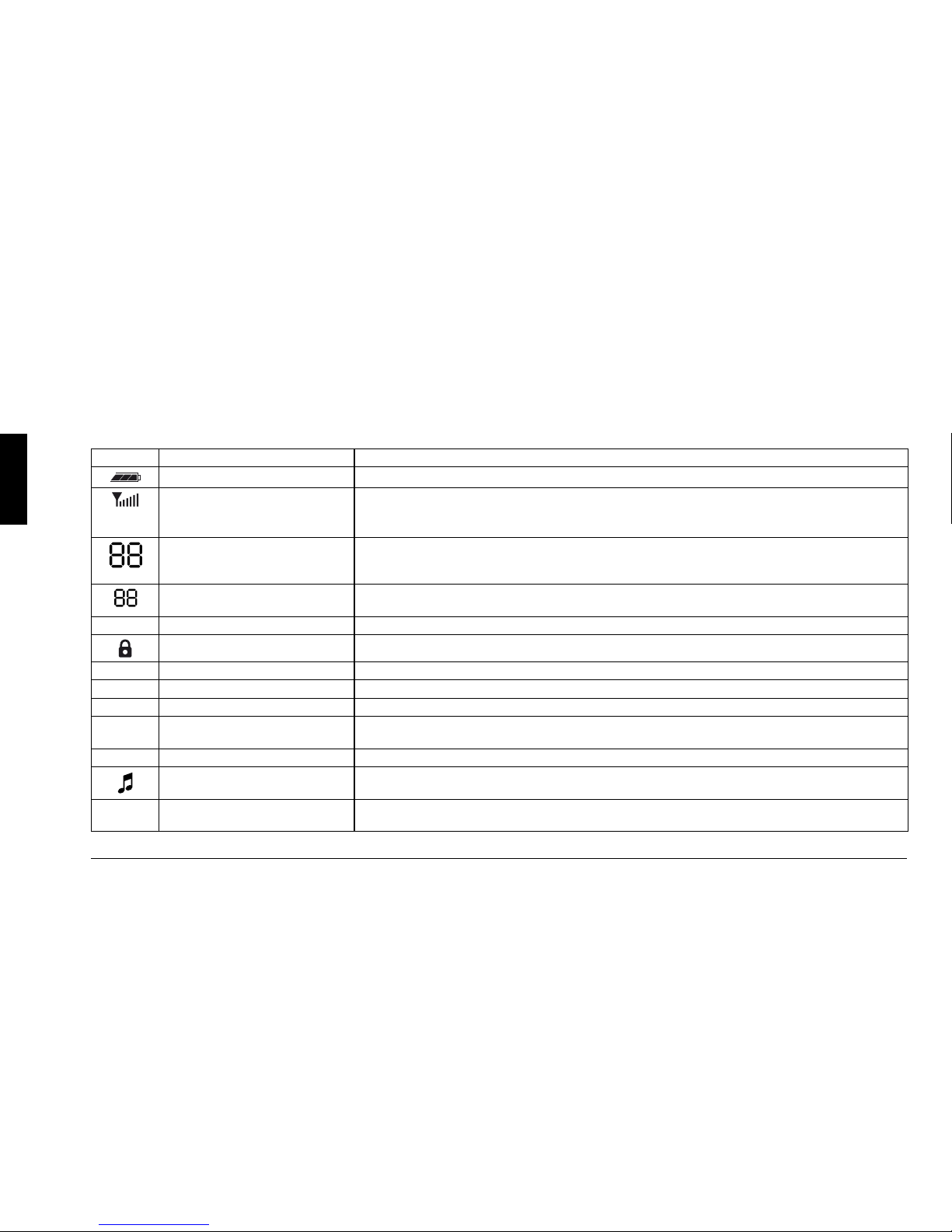
• Large display - 11 icons and 2+2 digits
• Out of range function - Warns the user when the device is out of
range
• E-VOX - Enables to communicate handsfree without audio
accessories or having to press buttons
• 1W audio power, suitable for noisy environments
• Hi/Lo power (active in the PMR band)
• In compliance with ETS 300 296-2 and ETS 300 086-2
• Built-in inversion scrambler - Protects communications
2Depending on the version, HP450 2A may be tted with a 2,200
mAh lithium battery or a 1,100 mAh Ni-MH battery.
• The version with high capacity lithium battery has an
autonomy of 26 hours
2The actual features available depend on the programmed
settings. For more information, contact an authorised distributor
or the radio link provider.
IThe resistance to immersion is guaranteed only if the battery
and protective cover of the connectors have been correctly
installed. In the event of accidental contact with water, the
device must be immediately dried.
2The manufacturer may change these features without warning as
a result of improvements applied to the products.

3
English
2 Safety information
2.1 Symbols used
IWarnings
2Practical recommendations that help to improve performance.
2.2 Warnings
Carefully read all the instructions contained in the manual and on the
labels applied to the device. The manufacturer has taken all possible
measures to ensure that all the information contained in this manual
is complete, accurate and current. However, CTE International
shall not be responsible for damages for which it is not directly
responsible. Modifications performed by unauthorized personnel
may affect the validity of the information contained in this manual.
• ThistransceiveriscompliantwithDirective99/05/EC.Beforeusing
the device, always refer to the restrictions on the use enclosed to
this manual.
• Always use the professional transceiver selected in compliance
with the regulations in force in the country of residence and
refrain from using it when its use is forbidden or if it is likely to
cause interference or serious hazards.
Attention
The portable HP450 2A extrá transceiver has been specifically
designed to guarantee a long-term safe and reliable operation.
For optimum and safe performance, always observe the basic
precautions applicable to all electric equipment:
Do not handle the transceiver by its aerial.
The use of a faulty aerial could seriously damage the
transmission power stages.
Do not keep the aerial of the radio too close to your
body during transmission.
Users with cardiac stimulators, acoustic implants
or medical devices should always consult their
doctor or the manufacturer of these devices to make
sure that they are adequately protected against RF
energy.
Do not use the radio close to unshielded primers in
explosive atmospheres.
The radio is designed to be used in extreme conditions.
However, it is always advisable to avoid exposing it
to very high or low temperatures (temperatures below
–20°C or above +55°C).
Do not expose the transceiver to excessive vibrations,
dust or rain.
Do not attempt to disassemble or repair the radio or
battery (except for performing the routine maintenance
operations described in this manual).
-20°C/+55°C

4
English
Use original accessories only in order not to damage
the radio.
Do not use the radio next to water sources and not
spill liquids on the radio.
If the transceiver gets wet, dry it immediately with a soft
and clean cloth.
Always remove the battery and switch the radio off
before cleaning it.
Verify that the supply source is compatible with the
battery-charger supplied (AC adapter).
Do not place any objects on the power cable of the
battery-charger in order not to damage it.
2.3 Technical support
Write the serial number of your transceiver in this space. This number
is printed on the nameplate inside the battery compartment of the
transceiver and must be provided for technical support and/or in the
event of loss and/or theft of the unit.
HP450 2A transceiver - Serial Number_______________________
3 Controls and functions
3.1 Description
3.1.a Front and left sides
1 Aerial
2 On/volume knob
3 Status LED – Red when the HP450 2A radio is in transmission
mode, green when it is in reception mode
1
11
10
9
8
2
5
6
7
3
4
12
15
13
14

5
English
4 LCD display – (O3.2)
5 pkey
6 qkey
7 Built-in microphone
8 Built-in speaker
9 MENU Key (O6)
10 SCAN/LOCK key – (O5.13)
11 HI/LO key– Enables to select a high or low transmission
power (not active in the PMR446 band - O5.11)
12 E (emergency) key – Enables to call the preset emergency
channel (not active in the PMR446 band - O5.12)
13 PTT (Push To Talk) key – Hold this button down to set the
transceiver in transmission mode
14 MON key – Hold this key down to enable the monitoring
function (O5.10);pressittwicequicklytoadjustthesquelch
15 CALL key – Press it briey to start the preset audio call
(tone)
3.1.b Rear and right sides
16 Battery pack – Powers the portable transceiver.
17 Battery pack lock – Enables to remove the battery pack from
the radio (O4.3.a).
18 Clipxing grooves– Enableto xthe optionalclip directly
onto the battery pack and hang the radio to your belt without
holster.
19 Battery recharge contacts – Enable to connect the battery-
charger to the desktop quick charger (O4.4).
20 Fixing screw - Fixes in place the protective cover of the
microphone connectors.
21 Protective cover of the microphone connectors.
22 SPK connector (under the cover) - 3.5 mm jack connector for
external speaker. Together with the MIC connector it can be
used to connect optional microphones.
23 MIC connector (under the cover) - 2.5 mm jack connector for
external microphone. Together with the SPK connector, it can
be used to connect optional microphones. This connector can
also be used for the Cloning feature (O6.7), which requires
however the connection of the special optional cable.
18
16
19
17
20
21
22
23

6
English
3.2 Displayed symbols
The transceiver has an LCD display that continuously displays information on the operating status of the radio.
Symbol Meaning Description
Battery charge Indicates the charge level of the battery.
Strength of the received and
transmitted signals
According to the number of bars displayed:
• Receptionmode-Indicatesthelevelofthereceivedsignals
• Transmissionmode- Indicates the level of the output power.
Radio/multifunctional channel In standby these large digits indicate the currently selected radio channel. During the programming of
features, they are used to display different parameters or values (for example bP=Beepthatconrms
that a key has been pressed).
Multifunctional indicator During programming, it is used to display different values and parameters.
For example on stands for ON (enabled feature) and oF stands for OFF (disabled feature).
LO Low TX power Indicates that a low transmission power has been selected.
Keyboard lock Indicates that the keyboard has been locked.
CTC CTCSS Indicates that the currently used channel has been programmed with a CTCSS tone.
DCS DCS Indicates that the currently used channel has been programmed with a DCS code.
SCAN Channel scan Indicates that the SCAN (automatic signal scan) is in progress on the preset channels.
P Priority channel Indicates that the currently selected channel has been programmed as a priority channel during the
scan.
DW Dual Watch Indicates that the Dual Watch (fast search of signals on two channels) is in progress.
Roger bip Indicates that the Roger bip function has been enabled.
VOX e-VOX Indicates that the e-vox (enhanced Voice Operated eXchange – handsfree transmission) has been
enabled.

7
English
4 Setup
4.1 Items supplied with the radio
Before using the transceiver, always make sure that the semi-rigid
EVA box contains the following items:
• Thetransceiverwiththerubber(xed)aerialandtherechargeable
battery pack
• Theholsterinrigidpolycarbonatewithrotatingcliptoxtheradio
to the belt. Toproperlyxtheradiointotheholster,pushthe
holster.
• Thedesktopbattery-charger(thatincludesthechargingseat,the
AC adapter and AC cable)
• Beltclip
• RubbercapfortheMike/SPKjacks
• Theoperatingmanual(thismanual)
If any of the above-described parts are missing or damaged,
immediately contact the retailer.
2To operate the radio, use the Ni-MH or Li-Ion battery pack.
4.2 Fixing/removing
the optional belt clip
To remove the clip from the battery pack,
unhook the battery pack from the radio,
then pull the release lever, situated on
the upper part of the clip, outwards, then
remove it pulling it upwards.
To reinsert the clip, insert the guides into
the grooves on the rear of the battery
pack, then slide the clip downwards until it snaps in place.
4.3 Removing/installing the battery pack
Depending on the model, the transceiver can be tted with the
following battery packs:
• BP4511-NiMHbatterypack,1,100mAh
• BP4522-Li-Ionbatterypack,2,200mAh
IIf you are planning not to use the transceiver for a long period
of time, remove the battery pack.
IBe careful not to soil/damage the contacts of the battery
compartment of the radio and battery pack.
4.3.a Removing/installing battery pack
To insert the battery pack:
1) Insertthebatterypackasshowninthegure.
2) Push the battery pack down towards the transceiver until it clicks
in place.
To remove the battery pack:
1) Press and hold down the battery release button.
2) Remove the battery pack from the upper side of the transceiver.
Lever
Guide
Groove
1
2

8
English
4.4 Recharging the battery pack
The fast double desktop battery-charger enables to recharge the
battery pack without removing it from the radio or to recharge the
battery pack separately. The charger is able to recharge both Li-Ion
and Ni-MH battery pack.
2At the end of the recharge operation, it is possible to leave the
radio/battery pack in the charger, because the latter has a special
protection that prevents the battery pack from being damaged by
overvoltages.
2Battery packs tend to loose their charge if they are not used
(automatic discharge). This condition is perfectly normal. All
models of battery packs tend to loose 10 - 20% of their power
after a few days.
IIf the battery pack is new, it is necessary to fully recharge
it before using it. Then, it is sufcient to follow the
recommendations given in paragraph 4.4.a.
IAlways use the battery-charger with the above-described
models of battery packs. Do not attempt to use the battery-
charger to recharge other types of batteries (and specically
alkaline batteries), as this operation could cause explosions
and personal injuries.
IAlways keep the battery-charger compartments clean.
4.4.a Recharging the radio with battery pack
New batteries are not charged.
The battery provides maximum efciency after 3-4 full charge/
recharge cycles.
1) Connect the connector of the transformer to that of the base.
2) Connect the plug of the
power cable of the adapter
to a grounded AC power
socket.
3) Verify that the radio has been
switched off.
4) Insert the radio into the
compartment of the battery-
charger, with the keyboard
facing upwards. The
recharge starts and the
orange indicator UNIT lights.
5) Once the recharge is
completed (see following
table), UNIT turns to green.
INDICATIVE TIME REQUIRED TO FULLY RECHARGE
THE BATTERY
Type of battery pack Recharge time (hours)
BP4511 (NiMH, 1,100 mAh) about 1 hour
BP4522 (Li-Ion, 2,200 mAh) about 2 hours
4.4.b External battery pack
Insert the battery pack into the compartment on the rear of the
battery-charger. BATT turns red. Once the recharge has completed,
BATT turns green.
‹‹

9
English
5 Basic features
5.1 Switching the device on and off
Turn the On/Volume knob clockwise until it clicks: the LCD displays
switchesonandthedeviceissuesaconrmationbeep.
2The backlighting of the LCD display switches off automatically
after ve seconds for energy saving purposes, while the display
remains on.
To switch the transceiver off, turn the On/Volume counterclockwise.
5.2 Backlighting
When you switch the device on or press one of the HI/LO, SCAN/
LOCK, MENU or MON keys, the device automatically enables the
backlighting for approximately ve seconds to allow you to read
the displayed messages if the lighting is not adequate. To keep the
backlighting on for 5 seconds more, press another key.
2The backlighting of the display consumes battery energy and
should therefore be used sparingly.
5.3 Checking the level of the batteries charge
When the transceiver is in standby mode, the battery charge indicator
continuously displays the residual charge of the battery.
2Icon indicates that the charge is insufcient and that the
device will soon switch off.
2The consumption of the battery charge is affected by the volume
level set.
5.4 Adjusting the squelch (suppressing background noise)
The radio is tted with a device called squelch that attenuates
the background noise when no signals are present. The enabling
thresholdcanbeadjustedaccordingtoyourspecicneeds.
1) Briey press MON twice. Sq displays, while the right section
displays a number from 1to 8, depending on the squelch level
you have set.
2) Press qseveral times to set the enabling threshold on 1(minimum
value). You will hear a slight background noise.
3) If the radio is not receving signals, press pseveral times to
gradually increase the squelch value and stop as soon as
you detect the minimum value that guarantees a stable noise
suppression.
4) Press PTT (or wait ve seconds). The device returns to the
standby mode and stores the settings you have selected.
2Make sure you do not set an excessively high squelch level
because in this case you may not be able to receive weaker
signals. On the other hand an excessively low squelch value
could enable the squelch even when no signals are present.
2This adjustment must be carried out within ve seconds, otherwise
the device returns to standby mode and stores the currently set
value.
ISquelch must always be adjusted when no signals are
present.
5.5 Selecting the operating channel
1) Press MENUonce.Thedisplayashes.
2) Press por qto select the desired channel. To quickly scroll the

10
English
channels hold down por q.
3) Press PTT(orwaitveseconds)tostorethesetting.
2It is obvious that other parties shall also have to select the same
channel, otherwise communications will not be possible.
2This adjustment must be carried out within ve seconds, otherwise
the radio returns to the standby mode storing the currently set
channel.
5.5.a How to select the channel
The HP450 2A radio has been programmed as follows:
• Channelsfrom1to 8are programmed with the 8 radio frequencies
of the PMR446 band
• Channels from 9 onwards are programmed with the same
repeated radio frequencies (for example channel 9has the same
frequency of channel 1, channel 10 has the same frequency of
channel 2, etc.), but also include CTCSS tones or DCS codes. If
you select these channels, CTC or DCS displays.
2For the PMR band, your dealer will inform you about the channels
to use
IIf you need to communicate with transceivers of different
brands, it is generally preferable to use one of the rst eight
channels to ensure maximum compatibility. It is obviously
necessary to select the less used channel of your area. If the
parties you are communicating with use a HP450 2A device
(or a device with CTCSS tones), you may choose any channel.
If all the eight PMR446 frequencies are occupied in your area,
you can select a channel from 9 to 16 (the less busy one) to
allow the CTCSS tone or DCS code to enable you to listen to
communications of the members of your group only.
2For more information on CTCSS tones and DCS codes, see O5.8
and 5.9.
5.6 Receiving and transmitting
2The reception/transmission mode described below is the so-called
"open trafc mode", which is simplest one. It is however possible
also to set other modes as described in paragraph 5.8.
During reception and transmission try and keep the aerial as vertical
as possible so that the signal can be transmitted without hindrances.
This precaution optimises the radio signal.
5.6.a Reception
As soon as the signal has been received, the squelch disables
automatically, the status LED turns green and icon displays
showing the intensity of the received signal.
2If the signal is received fragmented because of weak signals, try
using the monitoring feature.
5.6.b Transmission
1) Verify that other parties are not connected to the selected channel
(status LED off).
2) Hold PTT down: the status LED turns permanently red to indicate
that the transmission is in progress, while indicator indicates
the transmission power.
3) Waitafewseconds,thentalknormallyataboutvecentimetresfrom
the transceiver transmitter. Your message will be simultaneously
heard by all the parties listening to the same channel.
4) To end the communication, press PTT: the status LED switches
off to indicate that the device has returned to the reception mode

11
English
and icon disappears.
2Only one user at a time can talk during radio communications.
Therefore, it is important not to transmit when you are receiving a
communication and use the transmission mode sparingly to allow
other users to use the feature.
2Transmission consumes a signicant amount of energy and
should therefore be used sparingly to prolong the battery life.
Alternatively, it is also possible to select a low transmission
power.
2If you are unable to contact a station that you have no problems in
receiving, the station may be using CTCSS tones or DCS codes
(O5.8).
5.7 Busy channel lockout
The BCLO and TOT functions are disabled by default.
If BCLO has been enabled and the channel is busy, the selection of
PTT or CALL will have no effect and the radio will issue an error beep.
As soon as the channel is free, PTT and CALL shall automatically
resume ordinary operation.
5.7.a Transmission timer (TOT)
The HP450 2A radio can be programmed with a transmission timer
that temporarily blocks transmission if the radio has been used
beyond the maximum time permitted.
The radio is forced in reception mode if it continues transmitting
after the preset timer threshold has been reached. To restart the
transmission, it is sufcient to release and then press again the
PTT.
5.8 Operating modes (open or restricted traffic)
HP450 2A can be used in two modes:
Mode name: Default
setting
Comments
Opentrafc
(without CTCSS/
DCS)
From channel
1 to 8
Guarantees maximum
compatibility with the devices of
other manufacturers. However, if
the channel you are using is used
also by other parties, you will also
receive their communications.
Restrictedtrafc
(with CTCSS/
DCS)
From channel 9
onwards (with
several CTCSS
tones or DCS
codes)
CTCSS and DCS tones are
similar to access codes and
enable the radio to communicate
only with the parties that use the
same frequency or have set the
same code.
2For information on how to change the CTCSS tone or DCS code
of a channel programmed in restricted trafc mode, see O5.9.
2The restricted trafc mode enables several radios to use the same
radio frequency. However, if several parties (for example a user
of group A and a user of group B) simultaneously use the same
channel for transmission purposes, interference may occur. For
this reason, it is advisable not to transmit if the radio signals that
the channel is busy although there are no communications.
2The restricted trafc mode does not guarantee the privacy of
communications. In this mode it in fact possible to listen also
to parties that use CTCSS tones/DCS codes, although it is not
possible to call them because they would not be able to receive the

12
English
call. To communicate in condential mode, enable the scrambler
O6.5.
2If you need to use the HP450 2A radio next to electric equipment
that generates impulses that frequently enable the squelch of
the radio (that is the radio cannot be permanently silenced when
there are signals and noise can be occasionally perceived), it is
generally preferable to use the restricted trafc mode.
5.9 Programming the CTCSS/DCS codes
It is possible to change the CTCSS tones or DCS codes on all the
channels. You can set different codes in TX and RX.
5.9.a Selecting the CTCSS tones
1) Select the operating channel.
2) Press MENU twice. CTC displays on the left along with the
ashingvaluethathasbeensetontheright:oF (disabled) or a
number ranging from 1to 38 (CTCSS tone), depending on the
channel in use.
3) Press por qto select the CTCSS tone in RX.
4) Press PTTtostorethetone(orwaitveseconds).
5) Press MENU three times. The led blinks red.
6) Press por qto select the desired CTCSS tone in TX. Push PTT
to store the tone (or wait 5 seconds)
5.9.b Selecting the DCS codes
1) Select the operating channel.
2) Press MENU three times. DCS displays on the left along with the
ashingvaluethathasbeensetontheright:oF (disabled) or a
number ranging from 1to 83, depending on the DCS code used.
3) Press por qto select the DCS setting in RX.
4) Press PTTorwaitvesecondstostoretheDCS code.
5) Push MENU three times. The led blinks red.
6) Push p/qto select the DCS code in TX.Push PTT to store the
DCS code in TX.
5.9.c LED operation with CTCSS/DCS
Whenyou usethe restrictedtrafc mode,the statusLED provides
slightlydifferentindicationsascomparedtothoseoftheopentrafc
mode:
• Off: indicates that no signal is being received (as in the open
trafcmode)
• Green: indicates that a signal with a correct CTCSS/DCS tone is
being received (it is enabled together with the radio volume)
• Orange: indicates the receipt of a signal without a CTCSS/DCS
tone or with a different CTCSS/DCS tone (the volume will not be
enabled)
• Red: indicates that the transmission is in progress (as in the open
trafcmode)
5.10 Monitoring function - Monitor/squelch
This feature can be used to monitor the selected channel before
transmitting and receiving low intensity signals. Press MON to
disable the mode (CTCSS).
To disable the squelch (noise reduction), hold MON down for
approximately 3 seconds. In this mode, you can hear all the noise
present in the environment.
2The disabling of the squelch increases the consumption of the
battery power.

13
English
5.11 Selecting the transmission power
The HI/LO button is disabled in the PMR446 band.
In the PMR version, you can select the high or low power (1/5W).
The transmission power is displayed with the icon at the top left
of the screen.
5.12 Emergency mode
The Ebutton is disabled in the PMR446 band.
In Emergency mode, the only channel displayed is the emergency
one;thepoweroutputishighlevel.
5.13 Scan function
5.13.a Locking the keyboard
Hold down SCAN/LOCK for approximately three seconds to highlight
symbol (in the lower left section of the screen). All the functions of
the radio are temporarily disabled, except transmission (PTT), calls
(CALL) and the features for the adjustment of the squelch/monitor.
To release the keyboard, repeat the operation described. Symbol
disappears from the display.
2If the radio is in Scan or Dual Watch mode and you press SCAN/
LOCK, these features are disabled without the keyboard being
locked. To perform the latter operation, it is therefore necessary
to press the key once more.
5.13.b Channel scanning
This function is useful to keep a check on the channels previously
programmed by the programming software or by on authorised
dealer.
TostartthescanbrieypressSCAN/LOCK. SCAN displays.
During the scan you can also:
• ReplytoacallbypressingPTT.
To disable the scan, press once more SCAN/LOCK. SCAN disappears
from the display and the transceiver returns to the standby mode on
the channel that had been selected before starting the scan.
2If a priority channel has been programmed and you select it, P
displays in the lower left section of the screen.
IThe channels to scan must be previously enabled through
the programming software or by an authorised dealer.
5.13.c Dual Watch (dual listening mode)
This function enables you to scan two selected channels only.
1) Select the desired operating channel.
2) Press MENU. DW(DualWatch)ashesonthedisplayalongwith
oF (Dual Watch disabled).
3) Press por qto select the second channel.
4) Press PTT (or wait ve seconds) to enable the Dual Watch
feature.
DW displays in Dual Watch mode.
TodisabletheDualWatchfeature,brieypressSCAN/LOCK.

14
English
6 Functions of MENU key
1) Press MENU several times to highlight the desired function.
2) Press por qto set the selectable value for the displayed
feature.
The following table lists the features that can be set (the number of
times key MENU has to be pressed is indicated in the columns on
the left):
MENU Feature Display Disabled
1Selection of the operating channel (channel) NO
2Selection of the CTCSS tones CTC NO
3Selection of the DCS codes DCS NO
4Mode VOX YES
5Dual Watch DW YES
6Roger bip NO
7Keyboard tones bP NO
8Selection of the call tone CA NO
9Scrambler SC NO
10 Out of range indicator oU YES
11 Cloning (copying data between
radios)
CL NO
6.1 E-VOX
e-VOX (enhanced Voice Operated eXchange) enables to start a
transmission without pressing any keys, but by simply talking. The
sensitivityofe-VOXcanbeadjustedaccordingtoneeds;forexample
depending on whether you use the transceiver only or the optional
microphone or on whether you use the radio in a very noisy or noise-
less environment.
1) Press MENU several times until VOX ashes on the display
(normally 4 times). The right section of the displays shows the
current VOX setting (for example oF if the feature is disabled).
2) Press por qto highlight the number related to the desired
setting as shown in the following table:
No. Sensitivity Comments
oF - VOX disabled. transmission can be started only
by pressing PTT
1Minimum In this case you can talk even in a very low voice
and at a greater distance from the radio. However,
if the environment is too noisy, transmission may
be accidentally started by any noise.
2Medium Intermediate setting
3Maximum In this case you will have to talk in a loud voice
and close to the radio, but it is also possible to
use the radio in very noisy environments.
3) Press PTTtoconrm.
6.2 Roger bip
“Roger bip” is a short audio tone that the radio issues when you
release PTT at the end of the transmission. To enable/disable roger
bip:
1) Press MENU six times to highlight .
2) Press por qto enable or disable it.
3) Press PTTtoconrm.
2If the Roger bip feature has been enabled and the radio is in
standby mode, displays.

15
English
6.3 Keyboard tones
1) Press MENU to highlight bP (bip).
2) Press por qto enable or disable the keyboard tones.
3) Press PTTtoconrm.
2When you press one of the keys to disable the keyboard tones
(oF) in step 2, the radio will not issue a beep to conrm the
disabling. The re-enabling of the tones (on) is instead signaled
with a beep.
6.4 Selecting the call tone
BrieypressCALL tostartan audiocall.To select oneofthe ve
available tones:
1) Press MENU eight times. CA (CALL) displays on the left along
with the currently set value: oF (disabled) or 1, 2, 3, 4or 5,
according to the tone in use.
2) Press por qto select the desired setting. You can listen to the
tone you are setting through the speaker.
3) Press PTT to exit.
2If you select oF (Disabled), the call function shall be disabled.
Thus, the selection of CALL shall produce no effect.
6.5 Scrambler
The scrambler is designed to protect communications.
This feature prevents parties from other networks from hearing and
understanding voice communications.
To enable/disable the scrambler:
1) Press MENU nine times. SC (Scrambler)
2) Press por qto enable/disable the scrambler.
3) Press PTT.
If the scrambler is enabled, the status LED ashes in green (two
repeatedashesingreen).
2When the scrambler is enabled, it is not possible to clearly receive
communications. Therefore, before enabling it, it is necessary to
make sure that all the radios you wish to communicate with have
enabled this feature, otherwise you will not be able to communicate
with them.
2The scrambler of the transceiver does not fully guarantee the
safety of communications.
6.6 Out of range indicator
If this feature is enabled, the HP450 2A will issue a double beep
when the radio is out of range.
IThe radio with which you are communicating must also
enable this feature.
To enable/disable the out of range indicator:
1) Ask the other radio to enable the feature.
2) Press MENU till oU (Out of range) is displayed.
3) Press por qto enable or disable this feature.
4) Press PTT(orwaitveseconds).
6.7 Cloning (copying data between radios)
The Cloning feature enables to copy all the settings (for example
channels, CTCSS/DCS, call tones, enabled/disabled features) onto
one or more HP450 2A radios.

16
English
6.7.a Connection
1) Connect the two ends of the programming cable to the MIC
connectors of both radios.
6.7.b Enabling the Cloning feature
On the radio you wish to program (that receives the data):
1) Press MENU till the display shows CL (cloning)
2) Press q. CL displays followed by rE (receipt).
3) Press once more q. The status LED lights in green to indicate
that the radio is ready to receive the data.
On the programmed radio (that has already been programmed):
1) Press MENU till the display shows CL (cloning)
2) Press p. CL displays followed by tr (transmission).
3) Press once more p.ThestatusLEDashesinredandthedata
transfer is started.
4) At the end of the transfer operation, Pdisplays on the radio that
has received the data.
5) Press MENU on both radios to exit.
7. Connecting the audio accessories
To connect the optional microphones:
1) Verify that the radio has been switched off.
2) Loosenthescrew[20]thatxesinplacetheprotectivecover[21]
of the microphone connectors.
3) Remove the protective cover of the microphone connectors by
pushing the section labelled PUSH upwards.
4) Insert the jack of the microphone into the SPK and MIC slots of
the radio.
ToprotecttheMIC/SPKjacks(ifnotused),youcanxthesupplied
rubber cap: in this way you avoid xing and removing again the
plastic protective cover. Before xing the rubber cap to the radio,
insert the washer between the cap and the screw.

17
English
8 Care and maintenance
8.1 Cleaning the radio
Delicately clean the radio with a soft, clean and lint-free cloth. If the
radio is very dirty, dampen a cloth in a solution containing water and
detergent.
IDo not use detergents, alcohol or abrasive substances.
IDo not remove the protection of the side connectors and
the battery pack during cleaning. Do not wet connectors or
electric contacts.
8.2 Recharge contacts of the batteries
If the operations described above do not allow you to thoroughly clean
the recharge contacts of the battery pack [19], you can delicately rub
them with a clean eraser.
8.3 Connectors
When unused, connectors should be protected with the appropriate
cover.
IDo not connect the connectors to parts that have not been
supplied or recommended by CTE International as this could
damage the radio.
IThe resistance to immersion can be guaranteed only if the
protection of the connectors is rmly installed on the radio.
In the event of accidental immersion in water, immediately
dry the device.
8.4 Battery-charger
Always handle the radio in compliance with the above-described
precautions. Always keep seats and contacts clean.
IBefore performing cleaning operations, disconnect the
battery-charger from the mains.
8.5 Troubleshooting
HP450 2A has been designed to guarantee years of trouble-free
operation. However, if a failure occurs, please read the content of
this chapter before contacting the local service center.

18
English
8.5.a Table of solutions
Problem Possible cause Solution
The radio doesn't switch on The battery pack is discharged and/or has not been
installed correctly.
Verify that the battery pack is charged and that it has been
correctly installed.
The radio switches off shortly
after it has been switched on
Discharged battery pack. Recharge the battery pack.
The battery pack does not
recharge
The battery-charger has not been connected or
installed correctly.
Inspect the connections of the battery-charger and the
installation of the batteries.
The radio switches on but is
unable to receive signals
The site of installation is too shielded. Move to an another area.
The volume is too low Adjust the volume.
Incorrect CTCSS or DCS Check that the CTCSS tone or DCS code corresponds to the
one set by the parties you are communicating with.
Noise is always present in
reception mode
The monitoring function is enabled. Disable the monitoring function.
It is not possible to
communicate with other parties
An incorrect radio channel has been selected. Select the same radio channel used by the parties you are
communicating with.
The radio is installed in a shielded area or is too far
from the party you are communicating with
Move to another area.
Incorrect CTCSS or DCS Check that the CTCSS tone or DCS code corresponds to the
one set by the parties you are communicating with.
Reception is fragmented and/or
disturbed
The signal is very weak. Try temporarily disabling the squelch by means of the
Monitoring feature.
The transmission distance is excessive and/or there
are obstacles in the transmission path
Move closer to the party you are communicating with or to
another area.
Other parties are using the same channel Checkthetrafcontheradiochannelbymeansofthe
Monitoring feature and select another channel if required.
The radio has been installed too close to equipment
that causes interference (televisions, computers, etc.)
Increase the distance between the radio and this equipment.
Received communications are
not clear
Thescramblerhasbeenconguredonadifferent
setting as compared to that of the parties you are
communicating with (all the parties should either
enable or disable the scambler).
Select the same scrambler setting of the parties you are
communicating with.
Other manuals for HP450 2A Rugged
1
Table of contents
Other Alan Transceiver manuals