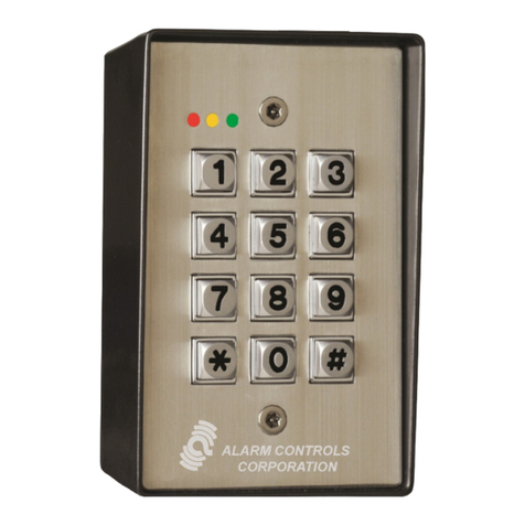
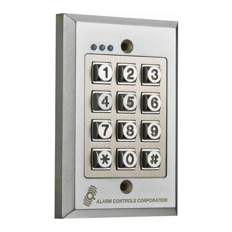
Alarm Controls Corporation KP-100 User manual

S
SE
EL
LF
F-
-C
CO
ON
NT
TA
AI
IN
NE
ED
D
D
DI
IG
GI
IT
TA
AL
L
K
KE
EY
YP
PA
AD
D
FULLY PROGRAMMABLE FROM THE KEYPAD
302 STAINLESS STEEL WALLPLATE WITH TAMPER-PROOF SCREWS
RECESSED OR SURFACE MOUNT, BACK BOX SUPPLIED
100 USER CODES WITH CODE LENGTHS FROM 4 TO 8 DIGITS
KEYS ARE BACKLIT FOR VISIBILITY IN DARK AREAS
HARD PLASTIC KEYS WITH AUDIBLE AND VISUAL KEY PRESS
SINGLE POLE - DOUBLE THROW RELAY CONTACTS RATED 5A.
BUILT-IN TAMPER SWITCH, BUILT-IN BUZZER
REQUEST TO EXIT INPUT
RED, YELLOW AND GREEN LEDS INDICATE KEYPAD STATUS
DESIGNED FOR INDOOR USE
LIFETIME LIMITED WARRANTY
M
MO
OD
DE
EL
L
K
KP
P-
-1
10
00
0
ALARM CONTROLS CORPORATION
DEER PARK, NEW YORK
11729
DESIGNED FOR ACCESS CONTROL APPLICATIONS

ALARM CONTROLS CORPORATION
IF YOU NEED IT, WE WILL MAKE IT
“QUALITY SECURITY EQUIPMENT SINCE 1971”
19 BRANDYWINE DRIVE, P.O. BOX 280, DEER PARK, NEW YORK 11729
1 800 645-5538 631 586-4220 FAX 631 586-6500
MODEL KP-100 DIGITAL KEYPAD
FOR
ACCESS CONTROL APPLICATIONS
USE DIODE
SUPPLIED
IF REQUIRED
EG
IN
N/C
TAMPER
SWITCH
12/24V
AC/DC
+
OUTPUT
N/C C N/O
RTE
INPUT
N/O CONTACT
REQUIRED
12/24 VOLT
POWER
SUPPLY
CONNECT
TO PANIC
INPUT -
MAGNETIC
LOCK
ELECTRIC
STRIKE
REQUEST TO
EXIT STATION
OR
TYPICAL WIRING DIAGRAM
SPECIFICATIONS
OPERATING VOLTAGE: 12 OR 24 VOLTAS AC/DC, AUTO SENSING
ACTIVE CURRENT DRAW : 50 MA. @ 12 VOLTS, 65 MA. @ 24 VOLTS
IDLE CURRENT: 9 MA. MAX. @ 12 VOLTS, 17 MA. MAX. @ 24 VOLTS
RELAY CONTACT RATING: 5A. @ 28 VDC/120 VAC
RELAY CONTACT ARRANGEMENT: SINGLE POLE-DOUBLE THROW, (1 FORM C)
EGRESS INPUT: NORMALLY-OPEN CONTACTS
100 USER CODES, CODE LENGTH FROM 4 TO 8 DIGITS LONG, DIGITS CAN BE REPEATED
KEYPAD LOCKOUT FEATURE
RELAY CAN BE SET FOR MOMENTARY OR LATCHING MODE
FALSE CODE LOCKOUT FEATURE
ADJUSTABLE RELAY ON TIME FROM 1 TO 999 SECONDS
KEYPAD BEEPER CAN BE SILENCED IF REQUIRED
KEYPAD CAN BE PROGRAMMED FOR OUTPUT ANNUNCIATION
BACKLIT KEYS FOR VISIBILITY IN DARK AREAS
SUPPLIED WITH SURFACE MOUNT BACK BOX WITH TAMPER SWITCH
CAN BE FLUSH MOUNTED ON SINGLE GANG ELECTRICAL BOX

SELF-CONTAINED DIGITAL
ACCESS CONTROL KEYPAD
MODEL KP-100
OPERATING INSTRUCTIONS
ALARM CONTROLS CORPORATION
19 BRANDYWINE DRIVE P.O. BOX 280
DEER PARK, NY 11729
WWW.ALARMCONTROLS.COM

TABLE OF CONTENTS
ALARM CONTROLS CORPORATION
19 BRANDYWINE DRIVE P.O. BOX 280
DEER PARK, NY 11729
DESCRIPTION OF KEYPAD ................................................................
FEATURES AND SPECIFICATIONS ....................................................
TYPICAL WIRING DIAGRAM ...............................................................
LED INDICATORS ................................................................................
DAP JUMPER .......................................................................................
EASY STARTUP ...................................................................................
ACTIVATING THE PROGRAM MODE ..................................................
KEYPAD INITIATION MODE .................................................................
ENTERING USER CODES ...................................................................
DELETING A USER CODE ...................................................................
SETTING RELAY ON TIME ..................................................................
EXITING THE PROGRAM ....................................................................
PROGRAMMING OPTIONS .................................................................
KEYPAD LOCKOUT .............................................................................
RELAY LATCHING MODE ....................................................................
KEYPAD SILENT MODE .......................................................................
OUTPUT ANNUNCIATION ...................................................................
AUTO ENTRY MODE ...........................................................................
FALSE CODE LOCKOUT .....................................................................
USER OPERATING INSTRUCTIONS ..................................................
WARRANTY .......................................................................................... PAGE 5
PAGE 1
PAGE 1
PAGE 1
PAGE 2
PAGE 2
PAGE 3
PAGE 3
PAGE 3
PAGE 3
PAGE 3
PAGE 3
PAGE 3
PAGE 4
PAGE 4
PAGE 4
PAGE 4
PAGE 4
PAGE 4
PAGE 4
PAGE 5

USE DIODE
SUPPLIED
IF REQUIRED
EG
IN
N/C
TAMPER
SWITCH
12/24V
AC/DC
+
OUTPUT
N/C C N/O
RTE
INPUT
N/O CONTACT
REQUIRED
12/24 VOLT
POWER
SUPPLY
CONNECT
TO PANIC
INPUT -
MAGNETIC
LOCK
ELECTRIC
STRIKE
REQUEST TO
EXIT STATION
OR
The KP-100 is a universal self-contained digital keypad with field proven reliability that will
operate on 12 or 24 volts AC or DC. This keypad is suitable for residential, industrial and
commercial installations and is compatable with all electric locking devices.
Programmed data is stored in a non-volitile EEPROM memory so all programmed data is not
lost in the event of a power outage.
IMPORTANT FEATURES
FULLY PROGRAMMABLE FROM THE KEYPAD
RECESSED OR SURFACE MOUNT, BACK BOX SUPPLIED
100 USER CODES WITH CODE LENGTHS FROM 4 TO 8 DIGITS
KEYS ARE BACK LIT FOR VISIBILITY IN DARK AREAS
KEYS ARE HARD PLASTIC WITH AUDIBLE AND VISUAL KEY PRESS FEEDBACK
10 AMPERE RELAY CONTACTS
BUILT-IN TAMPER SWITCH
BUILT-IN BUZZER
REQUEST TO EXIT INPUT
RED, YELLOW AND GREEN LEDS INDICATE THE CONDITION OF THE KEYPAD
TWO YEAR LIMITED WARRANTY
SPECIFICATIONS
OPERATING VOLTAGE: 12 OR 24 VOLTS AC/DC, AUTO VOLTAGE SELECTION
ACTIVE CURRENT DRAW: 50 MA. MAX. @ 12 VOLTS, 65 MA. MAX @ 24 VOLTS
IDLE CURRENT DRAW: 9 MA. MAX. @ 12V VOLTS, 17 MA. MAX. @ 24 VOLTS
RELAY CONTACT RATING: 10 A. @ 28 VDC/120 AC
RELAY CONTACT ARRANGEMENT: SINGLE POLE-DOUBLE THROW, (1 FORM C)
EGRESS INPUT: NORMALLY-OPEN CONTACTS, (RTE INPUT)
TYPICAL WIRING DIAGRAM
PAGE 1

ALARM CONTROLS
1 2 3
4 5 6
7 8 9
*0#
PAGE 2
YELLOW LED INDICATOR AND TONES
THE YELLOW LED AND BUILT-IN BUZZER GIVE THE FOLLOWING SIGNALS AND TONES
TONES CAN BE ENABLED OR DISABLED THROUGH PROGRAMMING
If the Installer Code is forgotten, use the DAP jumper to override the forgotten code
permitting the keypad direct entry into the programming mode. Do the following as described:
1. Disconnect the power supply.
2. Move the DAP jumper from OFF to ON position.
3. Reconnect the power supply, (the buzzer turns ON).
4. Move the DAP jumper back to the OFF position, (the buzzer turns OFF).
5. The keypad is now in the programming mode and ready to receive new programming data.
6. Since the old Installer Code was forgotten repeat # 2 in the Program Mode section.
LED SIGNALS TONES STATUS
ON NONE IN PROGRAMMING MODE
1 FLASH 1 BEEP SUCCESSFUL KEY ENTRY
2 FLASHES 2 BEEPS SUCCESSFUL CODE ENTRY
5 FLASHES 5 BEEPS FAULTY CODE ENTRY
CONTINUOUS FLASHING CONTINUOUS TONE DAP JUMPER NOT REPLACED
CONTINUOUS FLASHING NONE POWER ON
LED INDICATORS
DAP JUMPER (DIRECT ACCESS TO PROGRAMMING)
KP-100 KEYPAD
LEDS DAP JUMPER
RED GREEN
YELLOW
DAP
ON/OFF
MODEL
KP-100
RELAY
TAMPER
N/C +
AC/DC
NC NO
COM
EG
IN
RED LED ON WHEN OUTPUT RELAY IS LOCKED OUT
YELLOW LED MONITORS POWER INPUT AND KEY PRESS, (SEE CHART BELOW)
GREEN LED ON DURING THE TIME THE OUTPUT RELAY IS ACTIVE

To exit the program mode press the key.
To set the relay on time press then enter the relay on time, (relay on time is from 1 to
999 seconds), then press the key. The Yellow Led will flash twice and you will hear two
beeps. The relay on time has been entered. You must be in the Program Mode
40
In the event a User Code must be deleted do the following, press then enter the User
Number then press key. The Yellow Led will flash twice and you will hear two beeps.
The selected User Code has been deleted. You must be in the Program Mode.
#
#
You must be in the Program Mode
The User Codes can be from 4 to 8 digits in length, (digits can be repeated).
The User Codes must not be the same as the Installer Code
Press the key then enter the User Number, this number is two digits long and range
from 00 to 99, then enter the user code, then press the key. The Yellow Led will
flash twice and you will hear two beeps. You can now enter the User Codes.
An Installer Code must be entered in order to activate the Program Mode the first time.
1. Enter then press the key. The Yellow Led will be on steady, you will hear
two beeps. You will now be able to enter an Installer Code.
2. Press then enter an Installer Code that can be 4 to 8 digits in length,(digits can
be repeated), then press the key. The Yellow Led will be on steady, you will hear two
beeps. You are now in the Program Mode. Please record the Installer Code for future
use.
The Installer Code may be changed by entering the old Installer Code and repeating # 2.
PAGE 3
0
0
0
1
1
0 0 *
*
#
STEP 2 KEYPAD INITIATION MODE
Connect power to keypad. Voltage can be 12 or 24 AC or DC. When using DC voltage pola-
rity must be observed. Keypad has an auto voltage sensing circuit that detects the applied
voltage. THE FOLLOWING STEPS MUST BE TAKEN TO ACTIVATE THE KEYPAD !
STEP 3 ENTERING THE USER CODES
STEP 1 ACTIVATING THE PROGRAM MODE
The Keypad Initiation Mode allows 100 user codes in code lengths from 4 to 8 digits with
more than 100 million code combinations. This procedure must be followed !
To activate the Keypad Initiation Mode enter then press the key. The Yellow
Led will flash twice and you will hear two beeps. You are now in the Keypad Initiation Mode.
890 1 #
#
EXAMPLE OF ENTERING A FOUR DIGIT USER CODE
DELETING A USER CODE
SETTING THE RELAY ON TIME
LOCATION USER NUMBER USER CODE
1
TO ENTER PRESS
#
2
0 183
5
TO EXIT THE PROGRAM MODE
EASY START UP
When the keypad is programmed for Auto Entry mode the key that follows the entered
Code Number is not required. In this mode the User Code must be the same length as the In-
staller Code and the code length can be from 4 to 8 digits in length.
To program the keypad for Auto Entry press then press then press the key.
#
#
2
81
FALSE CODE LOCKOUT FEATURE
CODE ENTRY MODES/AUTO OR MANUAL
The keypad will lockout for 30 seconds after 10 false codes are entered.
The keypad generates 5 beeps for each unsuccessful code entry.
PAGE 4
PROGRAMMING OPTIONS
The keypad can be programmed with additional features by using the following options.
You have only 10 seconds between key entries otherwise the keypad will return
to the Program Mode. See ENTERING THE PROGRAM MODE on page 3.
The keypad must be in the Program Mode in order to install these options.
KEYPAD LOCKOUT
The keypad beeper can be silenced if required. The beeper will not sound when the keys
are pressed.
For silent keypad operation press then press then press the key. The keypad
is now in the Silent Mode. To restore to audible keypad operation press then press
then press the key. The keypad is now in the audible mode.
The relay can be programmed to turn on or off with each successive entry of the User Code.
Press then press the key. The relay will turn on or off depending upon its last
state. To return relay to Momentary Mode see SETTING THE RELAY ON TIME on page 3.
RELAY LATCHING MODE
#
0
3
8
#
1
3
8
KEYPAD SILENT MODE
#
1
4
The keypad can be programmed to notify the user when the output relay is energized or the
egress button has been pressed. This feature is ideal for use with a locking device that is silent.
The buzzer sounds for 1 second.
For Output Annunciation press then press then press the key. The keypad now
has output annunciation.
To disable Output Annunciation press then press then press the key.
#
#
1
8
1
8
OUTPUT ANNUNCIATOR
1
0
The keypad can be temporarily disabled to prevent unauthorized access at night or after office
hours by entering a predetermined lockout code which can be 4 to 8 digits long. The Red LED
will light when the Keypad Lockout is activated.
Press then press the key, then press and enter the lockout code, then
The Keypad Lockout is turned on and off by using the lockout code.
##
5121
When the keypad is programmed for Manual mode the key that follows the entered User
Coder is required. In this mode the the User Codes can be from 4 to 8 digits in length but all
the User Codes need not have the same number of digits.
To program the keypad for Manual Mode press then press then press the key.
The keypad is now in the Manual Mode.
#
2
80
#

OPERATING THE KEYPAD IN THE MANUAL MODE TO OPEN DOOR
Enter any of the programmed User Codes. (see page 3 for Programming User Codes)
then press key to open the door.
Yellow Led turns on for 1 second then turns off.
OPERATING THE KEYPAD IN THE AUTO ENTRY MODE TO OPEN DOOR
Enter the User Code which can be from 4 to 8 digits long.
door opens. Yellow Led turns on for 1
second then turns off.
USING THE KEYPAD LOCKOUT CODE IN THE MANUAL MODE
Enter the Keypad Lockout code which can be from 4 to 8 digits long.
then press key. The keypad is
locked out. The Red Led turns on. Re-enter the Lockout Code to unlock the keypad.
The Red Led turns off.
USING THE KEYPAD LOCKOUT CODE IN THE AUTO ENTRY MODE
Enter the Keypad Lockout code which can be from 4 to 8 digits long.
The keypad is locked out. The Red Led is
turned on. Re-enter the Lockout Code to unlock the keypad. The Red Led turns off.
PAGE 5
USER OPERATING INSTRUCTIONS
LIMITED WARRANTY
ALARM CONTROLS CORPORATION, (Seller), 19 BRANDYWINE DRIVE, DEER
PARK, NY 11729, warrants its Digital Keypads, (The Product), to be free from defects in
material and workmanship for two years from date of original purchase, under normal use
and service. Seller’s obligation is limited to repairing or replacing, at its option, free of
charge for parts and labor, or transportation, any part proven to be defective in material
and workmanship under normal use and service. Seller shall have no other obligation
under this warranty or otherwise if the product is altered or improperly repaired or serviced
by anyone other than the Seller.
THIS WARRANTY IS EXPRESSLY IN LIEU OF ALL OTHER WARRANTIES EXPRESS-
ED OR IMPLIED, INCLUDING THE WARRANTY OF MERCHANTABILITY AND FITNESS
FOR ANY PARTICULAR PURPOSE OR USE, AND IN NO EVENT SHALL SELLER BE
LIABLE FOR INCIDENTIAL OR CONSEQUENTIAL DAMAGES AS SAME ARE DEFINED
IN THE UNIFORM COMMERCIAL CODE.
ALARM CONTROLS CORPORATION
19 BRANDYWINE DRIVE P.O. BOX 280
DEER PARK, NY 11729
xxxxxx x x #
XXXXXX X X
#
XXXXXX X X
XXXXXX X X
Other manuals for KP-100
1
Table of contents
Other Alarm Controls Corporation Keypad manuals

Alarm Controls Corporation
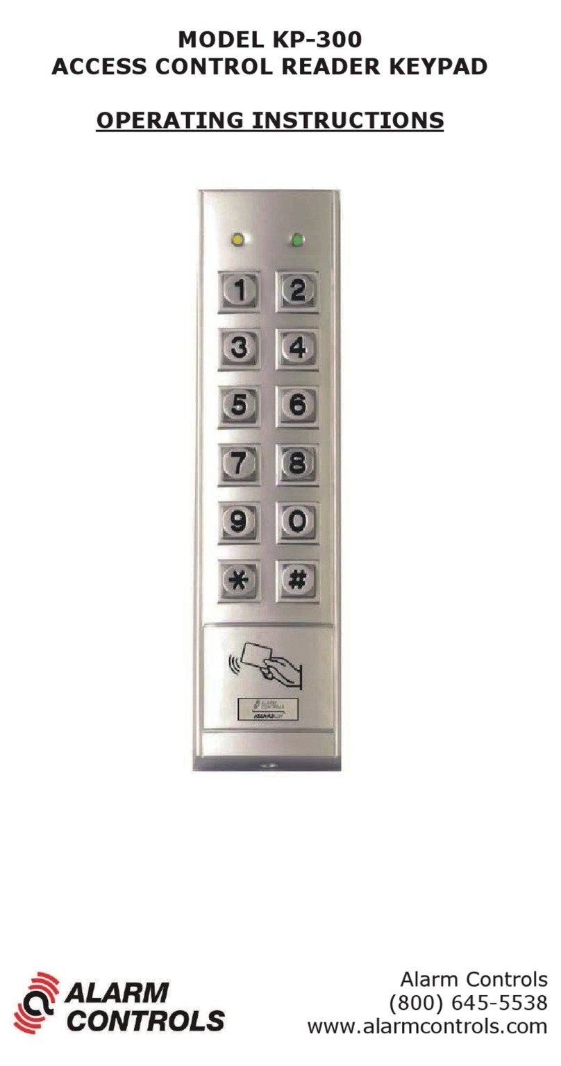
Alarm Controls Corporation KP-300 User manual

Alarm Controls Corporation
Alarm Controls Corporation KP-200 User manual

Alarm Controls Corporation
Alarm Controls Corporation KP-200 User manual

Alarm Controls Corporation
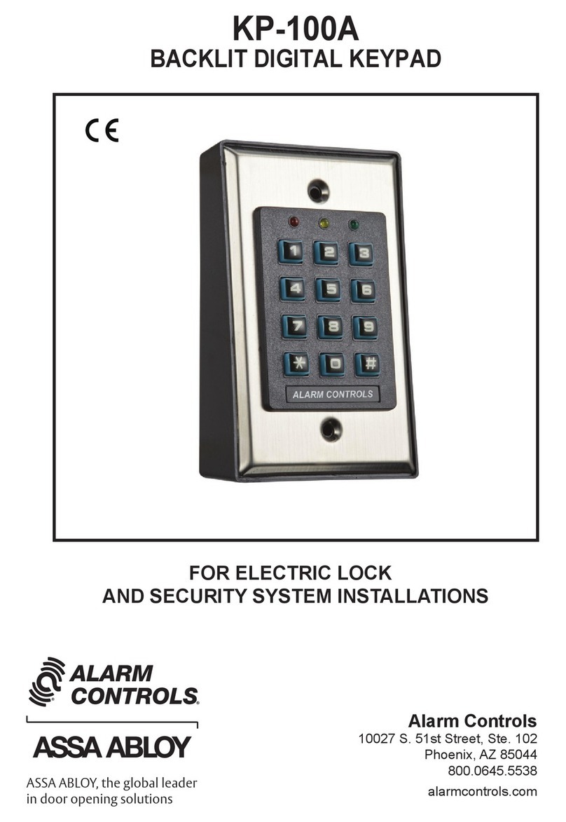
Alarm Controls Corporation KP-100A User manual

Alarm Controls Corporation
Alarm Controls Corporation KP-400 User manual