Alarm SAF PS5-M User manual

AlarmSaf
65A Industrial Way, Wilmington, MA 01887-3499, USA, Toll Free: 800-987-1050, Voice: 978-658-6717, Fax: 978-658-8638, www.alarmsaf.com
PS5-M Power Supply/Battery Charger with
Fire Alarm Input Module Installation Manual
This Installation manual is made up of the following separate Installation Instructions for the Power Supply
and Fire Alarm Input Module.
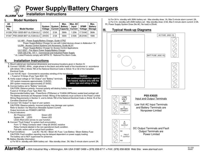
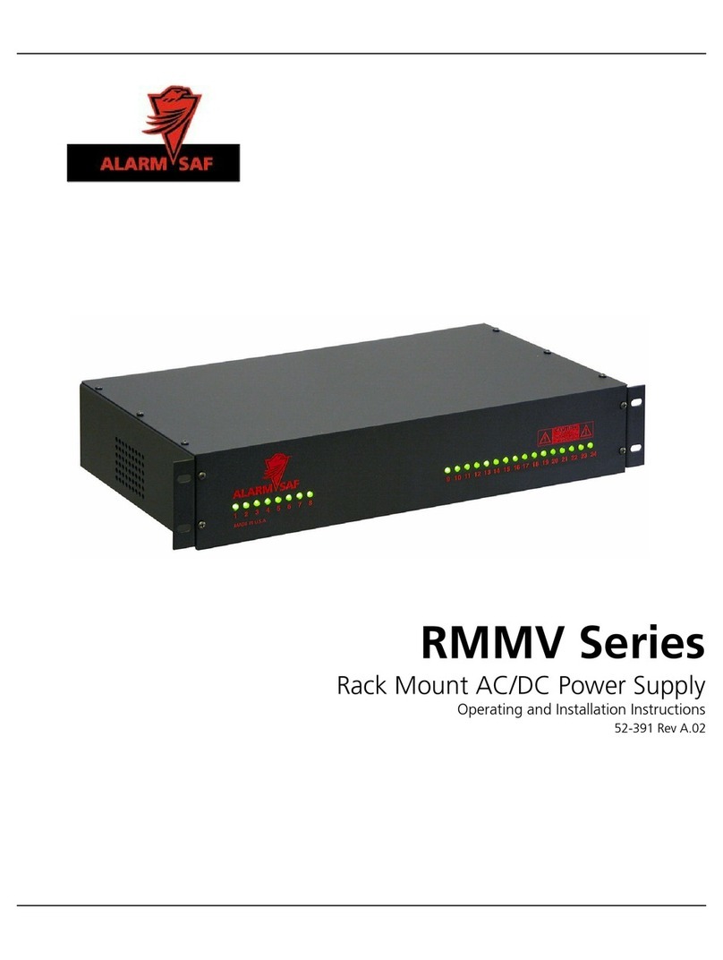
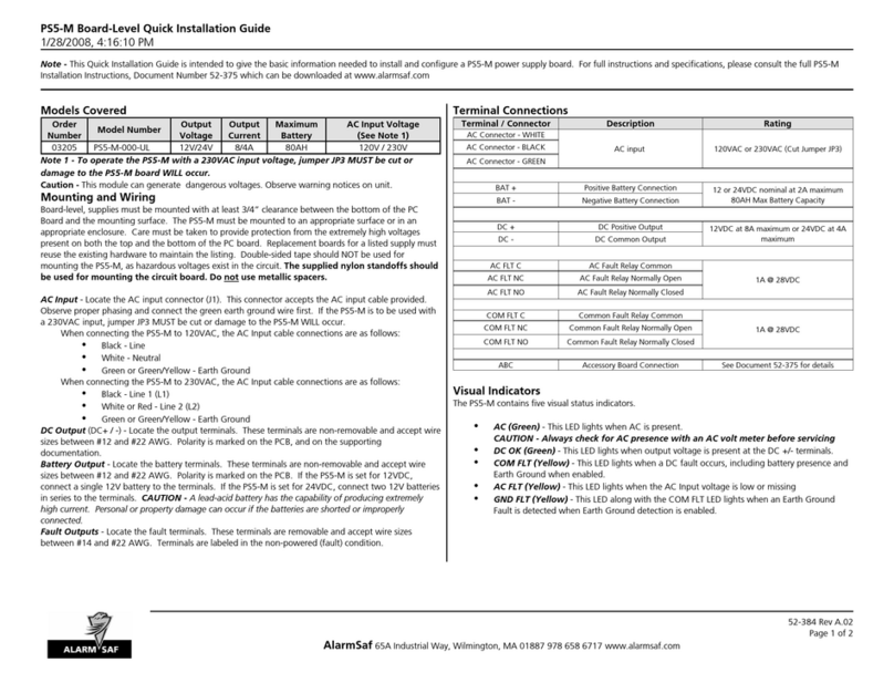
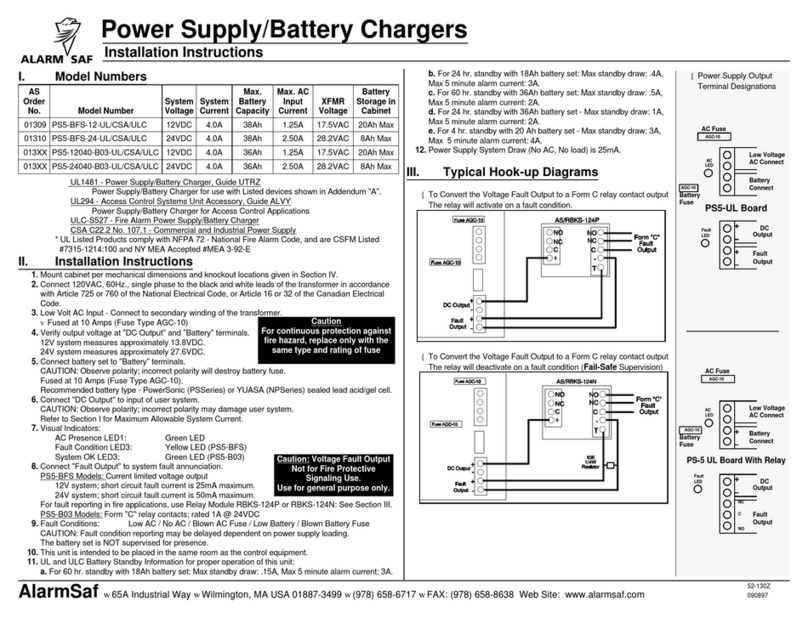
52-375 - Installation Instructions for PS5-M Power Supply - pp. 2-19
52-382 - Installation Instructions for FAI Module - p. 20-36

JP3
DC -DC +BAT -BAT +
JP5JP6 JP7
BUSS 2 BUSS 1
J4 ABC
COM FLTAC FLT
COM
FLT
GND FLT
AC FLT
VOLTAGE
SELECT
24V
12V
BAT
DETECT EARTH GND
DETECT
AC ON
EARTH HOT NEUTRAL
J1
BATTERY FUSE
Model PS5-M
Power Supply / Battery Charger
Operating and Installation Instructions
52-375 Rev A.03

I. Warnings and Notices
WARNING - Do not touch the heat sinks on the PC board while the unit is powered
as there is a possibility of electric shock
WARNING - To reduce the risk of fire or electric shock, do not expose this product
to rain or moisture
WARNING - This installation and all servicing should be made by qualified service
personnel and should conform to all local codes
NOTICE - This equipment shall be installed in a manner which prevents
unintentional operation from employees or other personnel working about the
premises, by falling objects, by building vibration and by similar causes
NOTICE - This equipment is not intended for use within the patient care areas of a
Health Care Facility
Symbol Definitions
WARNING - Read the instruction manual to avoid personal injury or property damage
ᏘWARNING - Risk of electric shock. Service to be performed by a qualified service person
PS5-M Installation Instructions
February 23, 2012
52-375 Rev A.03
Page 2 of 18
AlarmSaf 65A Industrial Way, Wilmington, MA 01887 978 658 6717 www.alarmsaf.com

Table of Contents
186.3 Mechanical Specifications
186.2 Temperature Specifications
186.1 Electrical Specifications
186 Specifications
175.4 Troubleshooting
165.3 Visual Indicators
155.2 Jumper Settings
155.1 Output Voltage Selection
155 Operating the PS5-M
144.2 Wiring
134.1 Mounting
134 Installation
123.8 Fusing
113.7 Fault Reporting Terminals
103.6 Battery Terminals
103.5 Output Terminals
93.4 ABC Connectors and Harnesses
83.3 AC Input Connection
73.2 Connector Descriptions and Electrical Ratings
63.1 Electrical Ratings and Specifications
63 System Overview
52 Applicable Standards / Documents
41 Introduction
2I. Warnings and Notices
PageSection
PS5-M Installation Instructions
February 23, 2012
52-375 Rev A.03
Page 3 of 18
AlarmSaf 65A Industrial Way, Wilmington, MA 01887 978 658 6717 www.alarmsaf.com

Section 1
Introduction
The PS5-M is an off-line switching (OLS) power supply designed for use in the access control, fire
industry, and related industries by the systems integrator. It accepts a variety of accessory boards
designed to increase the functionality of the basic power supply.
Features:
Field selectable regulated output voltage of 12V or 24 VDC
Units provide twice the current capability when set to 12 VDC as at 24 VDC. This is to
compensate for the typically double current draw of 12V devices such as maglocks.
Expandable with plug-in accessory boards via the ABC connector - ABC connector can power
either of two available power busses, Buss 1 or Buss 2
All units can charge up to 80 AH of battery within 48 hours (40 AH in 24 hours) while supplying
full rated load
Full fault detection, including battery presence and ground fault detection, and reporting via two
form-C relay contacts; AC fault and Common Fault
Fault conditions monitored include:
Low or missing AC
High or low output / battery
Blown fuse
Missing battery (optional via jumper)
Reversed Battery
Earth Ground Fault (optional via jumper)
Internal Power Supply failure
Visual indicators include:
AC Presence (Green)
DC Output Presence (Green)
Earth Ground Fault (Yellow)
AC Fault (Yellow)
System Trouble (Yellow)
PS5-M Installation Instructions
February 23, 2012
52-375 Rev A.03
Page 4 of 18
AlarmSaf 65A Industrial Way, Wilmington, MA 01887 978 658 6717 www.alarmsaf.com

Section 2
Applicable Standards / Documents
NFPA Standards
NFPA 72 National Fire Alarm Code
NFPA 70 National Electrical Code
NFPA 731 Standard for the Installation of Electronic Premises Security Systems
US Standards
UL 294 Access Control System Units
UL 1481 Power Supplies for Fire Protective Signaling System
UL 1076 Proprietary Burglar Alarm Units and Systems
UL 2044 Commercial Closed-Circuit Television Equipment
Canadian Standards
ULC S527 Standard for Control Units for Fire Alarm Systems
ULC S318 Standard for Power Supplies for Burglar Alarm Systems
CAN/CSA-C22.2 No. 107.1-01 General Use Power Supplies
Other
Applicable Local and State Building Codes
Requirements of the Local Authority Having Jurisdiction (LAHJ)
FCC Compliance
This equipment has been tested and found to comply with the limits for Class A digital device
pursuant to Part 15 of FCC rules.
These limits are designed to provide reasonable protection against harmful interference when this
equipment is operated in a commercial environment.
This equipment generates, uses, and can radiate radio frequency energy and, if not installed and used
in accordance with the instruction manual, may cause harmful interference to radio communications.
Operation of this equipment in a residential area is likely to cause harmful interference, in which case,
the user is required to correct the interference at his/her own expense.
PS5-M Installation Instructions
February 23, 2012
52-375 Rev A.03
Page 5 of 18
AlarmSaf 65A Industrial Way, Wilmington, MA 01887 978 658 6717 www.alarmsaf.com
Section 3
System Overview
3.1 Electrical Ratings and Specifications
Manufactured By
www.alarmsaf.com
Fax: 978 658 8638
Wilmington, MA 01887
Tel: 978 658 6717
65A Industrial Way
Tel: 800 987 1050
AlarmSaf
Model Number (Power Supply Module Only)
PS5-M
Electrical Ratings
80 AH (48 hour charge), 40 AH (24 hour charge)Maximum Battery Capacity
7 AH (4 hour charge)Minimum Battery Capacity
<0.25% typical, <0.50% during battery chargeRipple
~85%Efficiency
12 VDC at 8 amperes or 24 VDC at 4 amperes (96 Watts max)Output
80 mA Maximum (Plus total output load including accessory boards)Standby Load (While on Battery)
170W maxInput Power
All Models: 120 VAC or 230 VAC nominal @ 50-60 HzInput Voltage
Product Use
When installed in accordance with all standards listed in Section 2 of this document, the PS5-M
provides power for use with typical 12 or 24 VDC as used in the access control, fire, CCTV, or security
industries such as, but not limited to, mag locks, door strikes, door holders, smoke dampers, four
wire smoke detectors, card readers, keypads, etc.
PS5-M Installation Instructions
February 23, 2012
52-375 Rev A.03
Page 6 of 18
AlarmSaf 65A Industrial Way, Wilmington, MA 01887 978 658 6717 www.alarmsaf.com

3.2 PS5-M Connector Descriptions and Electrical Ratings
AC Fault Relay - CommonAC FLT - COM
AC Fault Relay - Normally ClosedAC FLT - NC 1A @ 24 VDC
0.5A @ 120 VAC
AC Fault Relay - Normally OpenAC FLT - NO
System Fault Relay - Normally OpenCOM FLT - NO
System Fault Relay - Normally ClosedCOM FLT - NC 1A @ 24 VDC
0.5A @ 120 VAC
System Fault Relay - CommonCOM FLT - COM
J3 - Fault Contacts
Battery Common ConnectionBAT-
12 or 24 VDC nominal @ 2 Amperes Max
80 AH Maximum Battery Capacity
Battery Positive ConnectionBAT+
DC Common OutputDC-
12 or 24 VDC at full output current of supply - See
Section 3.1 for ratings.
DC Positive OutputDC+
J2 - DC Power and BAT Output
12 or 24 VDC at full output current of supply - See
Section 3.1 for ratings.
ABC OutputJ4
120 VAC or 230 VAC Nominal @ 50-60 Hz
Must be configured for 230 VAC prior to use. See
Fig.3.3.1
5-Pin AC Line connector
J1
RatingDescriptionTerminal / Connector
Figure 3.2.1
JP3
DC -DC +BAT -BAT +
JP5JP6 JP7
BUSS 2 BUSS 1
J4 ABC
COM FLTAC FLT
COM
FLT
GND FLT
AC FLT
VOLTAGE
SELECT
24V
12V
BAT
DETECT EARTH G ND
DETECT
AC ON
EARTH HOT NEUTRAL
J1
BATTERY FUSE
BATTERY CONNECT
FIELD WIRING TERMINALS
DC OUTPUT
FIELD WIRING TERMINALS
COMMON FAULT
FIELD WIRING TERMINALS
AC FAULT
FIELD WIRING TERMINALS
ABC ACCESSORY
CONNECTOR
AC POWER
CONNECTOR
Note: Unit may have a delayed initial power up of approximately 5 seconds due to internal
diagnostic processes when there is no battery set connected.
Note: Wire should be sized appropriately for voltage drop and current carrying capability. All
terminals are labeled for polarity where appropriate.
PS5-M Installation Instructions
February 23, 2012
52-375 Rev A.03
Page 7 of 18
AlarmSaf 65A Industrial Way, Wilmington, MA 01887 978 658 6717 www.alarmsaf.com
3.3 AC Input Connection
The AC input for the PS5-M is made through a fully shrouded pluggable cable which plugs into the
AC Power input connector plug (J1). Connection to the harness should be made via wire nut to an
appropriate AC source.
The PS5-M accepts a nominal AC input of 120 or 230 VAC at 50 to 60 Hz.
Caution - Use an AC voltmeter to verify that the main AC power is not energized prior to
connecting the PS5-M.
When connecting the PS5-M to 120 VAC, the AC Input cable connections are as follows:
Black - Line
White - Neutral
Green or Green/Yellow - Earth Ground
When connecting the PS5-M to 230 VAC, the AC Input cable connections are as follows:
Black - Line 1 (L1)
White or Red - Line 2 (L2)
Green or Green/Yellow - Earth Ground
CAUTION - Be sure to cut jumper JP3 and remove when using a 230 VAC Input or damage to
the supply will occur. See Figure 3.3.1.
Note - The AC input connector is a convenient means for AC disconnect, since the connector is fully
shrouded when disconnected.
Note - The Green or Green/Yellow earth ground wire should always be connected first or
disconnected last for safety.
Note - All wiring should be installed in accordance with (NEC760) NFPA70, NFPA72, and all local
code requirements. Power limited wiring requires that power limited and non-power limited wiring
remain physically separated. All power limited circuits must remain at least one quarter inch (¼”)
away from any non-power limited circuit wiring. All power limited circuit wiring must enter and exit
the cabinet through different knockouts than non-power limited wiring.
Fig. 3.3.1
JP3
EARTH HOT NEUTRAL
J1
AC POWER
CONNECTOR
AC POWER
CONFIGURATION JUMPER
PS5-M Installation Instructions
February 23, 2012
52-375 Rev A.03
Page 8 of 18
AlarmSaf 65A Industrial Way, Wilmington, MA 01887 978 658 6717 www.alarmsaf.com

3.4 ABC Connectors and Harnesses
3.4.1 The ABC buss supplies the output voltage and fault status to and from compatible accessory
boards. The voltage is carried by either pins 5 and 6 or pins 7 and 8 of the ABC connector (J4). By
appropriate positioning of the fuse associated with JP5, JP6, and JP7, the PS5-M output can be
connected to other accessory boards in the system for distribution by either Buss 1 or Buss 2. See
Section 5.2 for additional information on selection of Buss 1 or Buss 2.
3.4.2 Cable Types
ABC-0418 inchesBrown005228-8
ABC-038 inchesBrown005218-8
DescriptionLengthColorAS PNCable Type
ABC-03 Used to connect the PS5-M to an accessory board or to connect accessory board to
accessory board over short distances.
ABC-04 Used to connect the PS5-M to an accessory board or to connect accessory board to
accessory board over longer distances.
Figure 3.4.1
JP5JP6 JP7
BUSS 2 BUSS 1
J4 ABC
COM FLTAC FLT
COM
FLT
GND FLT
AC FLT
ABC ACCESSORY
CONNECTOR
BUSS 1 SELECT
BUSS 2 SELECT
PS5-M Installation Instructions
February 23, 2012
52-375 Rev A.03
Page 9 of 18
AlarmSaf 65A Industrial Way, Wilmington, MA 01887 978 658 6717 www.alarmsaf.com
3.5 Output Terminals
The PS5-M has one set of output terminals labeled DC+ and DC- which provides a constant regulated
output of either 12 VDC or 24 VDC. The DC OK LED (D15) indicates that voltage is available at the
output terminals. See Section 5.1 for additional information on voltage selection.
Caution - Observe the polarity of the PS5-M output terminals with respect to the load or damage to
the load may occur.
3.6 Battery Terminals
The PS5-M has one set of battery terminals labeled BAT+ and BAT- which will charge up to 80
amphours within 48 hours or up to 40 amphours within 24 hours. The output is fuse protected.
Caution - Observe the polarity of the PS5-M battery terminals with respect to the battery set or
damage to the load, power supply, or battery set may occur.
Note - When there are no batteries on the PS5-M, it is normal for there to be no voltage on the
battery terminals. The charger does not enable until it senses a battery on the terminals.
Note - Connecting batteries in parallel does not allow the PS5-M to supervise the entire battery set
for presence.
Note - Series-connected batteries should always be of the same amphour capacity, age, and
state-of-charge to prevent battery / system damage.
Note - It is the responsibility of the installer to determine the minimum battery requirement for the
particular application in which the supply is being used. Backup batteries should be serviced at
regular intervals as determined by local and/or national codes.
DC -DC +BAT -BAT +
BATTERY FUSE
BATTERY CONNECT
FIELD WIRING TERMINALS
DC OUTPUT
FIELD WIRING TERMINALS
DC OK
DC OK
VISUAL INDICATOR
Figure 3.5.1
PS5-M Installation Instructions
February 23, 2012
52-375 Rev A.03
Page 10 of 18
AlarmSaf 65A Industrial Way, Wilmington, MA 01887 978 658 6717 www.alarmsaf.com
3.7 Fault Reporting Terminals
The fault reporting relay connections are made through removable terminal strip, J3. Separate Form
C relays are provided for AC Fault and Common Fault. Six fault terminals are available:
1. AC FLT Common (COM)
2. AC FLT Normally Closed (NC)
3. AC FLT Normally Open (NO)
4. COM FLT Common (COM)
5. COM FLT Normally Closed (NC)
6. COM FLT Normally Open (NO)
The fault outputs employ “Fail-safe” operation and are held powered in a non-fault condition. Board
legend shows relay condition in the non-powered, or fault, state.
Fig. 3.7.1
JP5JP6 JP7
BUSS 2 BUSS 1
J4ABC
COM FLTAC FLT
COM
FLT
GND FLT
AC FLT
COMMON FAULT
FIELD WIRING TERMINALS
AC FAULT
FIELD WIRING TERMINALS
C
NC
NO
C
NC
NO
No Fault / FaultFaultInternal Fault
No FaultFaultReversed Battery Connection
No FaultFaultBlown Battery Fuse
FaultFaultBlown AC Fuse - Battery Low
FaultNo FaultBlown AC Fuse - Battery Charged
No FaultFaultHigh or Low Output Voltage
No FaultFaultHigh or Low Battery
No FaultFaultMissing Battery (Battery Presence Enabled)
FaultFaultLoss of / Low AC - Battery Low
FaultNo FaultLoss of / Low AC - Battery Charged
No FaultNo FaultNormal Condition - No Faults
AC FLT Relay / AC FLT LED
COM FLT Relay / COM
FLT LED
Fault Condition
PS5-M Installation Instructions
February 23, 2012
52-375 Rev A.03
Page 11 of 18
AlarmSaf 65A Industrial Way, Wilmington, MA 01887 978 658 6717 www.alarmsaf.com

3.8 Fusing
The PS5-M contains two replaceable fuses - the Battery Fuse and the ABC Buss Fuse. When replacing
these fuses, only the equivalent type and rating are to be used. The PS5-M utilizes commonly
available Automotive Miniature fuses (Type ATM). Both fuses are rated at 15A (ATM-15).
The AC Input fuse is a soldered-in non-replaceable fuse. If it is determined that this fuse has opened,
the PS5-M board must be returned to AlarmSaf for repair.
PS5-M Installation Instructions
February 23, 2012
52-375 Rev A.03
Page 12 of 18
AlarmSaf 65A Industrial Way, Wilmington, MA 01887 978 658 6717 www.alarmsaf.com

Section 4
Installation
4.1 Mounting
4.1.1 Wall Mounting
If the PS5-M is provided in a wall mount enclosure, use #8 hardware minimum in four locations.
Use an appropriate fastening system for the mounting surface.
Cabinet Mounting:
1. Mark and pre-drill two holes for the top keyhole mounting screws
2. Install two fasteners in the mounting wall leaving screw heads protruding approximately ¼
inch
3. Using the two upper keyholes, mount the cabinet over the two screws
4. Mark the two lower holes, remove the cabinet and drill the lower mounting holes
5. Mount the cabinet, install the remaining fasteners, and tighten all fasteners
BN
ABC
Figure 4.1.1
4.1.2 Rack Mounting
If the PS5-M is provided as part of a rack-mount system, consult the instruction set for the
system-level product for mounting instructions.
PS5-M Installation Instructions
February 23, 2012
52-375 Rev A.03
Page 13 of 18
AlarmSaf 65A Industrial Way, Wilmington, MA 01887 978 658 6717 www.alarmsaf.com

4.2 Wiring
4.2.1 Wire Routing
All wiring must be installed in accordance with NFPA70, NFPA72, and all local code requirements.
Power Limited wiring requires that power limited and non-power limited wiring remain physically
separated. Any power limited circuit entering the enclosure must remain at least one quarter inch
(¼”) away from any non-power limited circuit wiring. Any power limited circuit wiring must enter
and exit the enclosure through different knockouts than non-power limited circuit wiring. Wiring
within the enclosure should be routed around the perimeter of the cabinet. It should not be
routed across the circuit boards.
4.2.2 AC Input
Connection should be made via wire nut. AC mains wiring should be no smaller than 14 AWG.
See Section 3.3 for details.
4.2.3 ABC Connector
See section 3.4
4.2.4 Output Wiring
Locate the output terminals. These terminals are non-removable and accept wire sizes between
#12 and #22 AWG. Polarity is notated on the PCB, and on the supporting documentation.
4.2.5 Battery Wiring
Locate the battery terminals. These terminals are non-removable and accept wire sizes between
#12 and #22 AWG. Polarity is notated on the PCB. If the PS5-M is set for 12 VDC, connect a
single 12V battery to the terminals. If the PS5-M is set for 24 VDC, connect two 12V batteries in
series to the terminals.
Note - Connecting batteries in parallel does not allow the PS5-M to supervise the entire battery
set for presence when an individual battery is removed.
CAUTION - A lead-acid battery has the capability of producing extremely high current.
Personal or property damage can occur if the batteries are shorted or improperly
connected.
4.2.6 Fault Relay Wiring
Locate the Fault Relay Output terminal block (J3) and remove the terminal block from the header.
Connect the wiring for the fault outputs to the terminal block. See section 3.2 for the
connections for each relay. Replace the terminal block on the header.
Note - The relays are labeled in the non-powered (fault) state. Under a no-fault condition, the
relays are powered (i.e. Common to Normally Open connected).
PS5-M Installation Instructions
February 23, 2012
52-375 Rev A.03
Page 14 of 18
AlarmSaf 65A Industrial Way, Wilmington, MA 01887 978 658 6717 www.alarmsaf.com

Section 5
Operating the PS5-M
5.1 Output Voltage Selection
Before powering a system containing a PS5-M, the output voltage switch (SW1 - Voltage Select) must
be set for the proper output voltage or damage to the system could occur. Do not change the switch
setting while the unit is powered or damage to the system may occur. Set the switch towards the
green AC Visual Indicator for 12V, away from the green AC Visual Indicator for 24V (the PC board is
labeled with the voltage settings).
VOLTAGE
SELECT
24V
12V
BAT
DETECT EARTH GND
DETECT
AC ON
OUTPUT VOLTAGE
SELECT SWITCH
EARTH GOUND
DETECTION ENABLE
BATTERY PRESENCE
DETECTION ENABLE
AC PRESENCE
VISUAL INDICATOR
12V
24V
Figure 5.1.1
5.2 Jumper Settings
For proper operation, the jumpers on the PS5-M should be set appropriately. These jumpers may be
set with the unit powered or un-powered.
Buss 1 (JP5 & JP7)See section 5.2.3ABC Buss Select
JP5, JP6, JP7 (Buss 1 / Buss
2)
Enable
Jumper On - Enable
Jumper Off - Disable
Earth Ground Fault
Detection
JP9 (Earth Ground Detect))
Enable
Jumper On - Enable
Jumper Off - Disable
Battery Presence Fault
Detection
JP10 (Bat Detect)
DefaultSettingsDescriptionJumper
5.2.1 JP10 (Bat Detect) - Battery Presence
This jumper allows disabling of the battery presence detection for applications where no backup
battery set is used.
PS5-M Installation Instructions
February 23, 2012
52-375 Rev A.03
Page 15 of 18
AlarmSaf 65A Industrial Way, Wilmington, MA 01887 978 658 6717 www.alarmsaf.com

5.2.2 JP9 (Earth Ground Detect)
This jumper allows disabling of the Earth Ground Fault detection for applications that either don’t
require Earth Ground Fault detection, or for applications where Earth Ground Fault detection is
already provided by other equipment.
5.2.3 JP5, JP6, JP7 (Buss 1 / Buss 2)
The fuse associated with JP5, JP6, and JP7 determines whether the output of the PS5-M connects
to Buss 1 or Buss 2 of the ABC connector. See Figure 3.7.1
Fuse between JP5 and JP7 connects the PS5-M to Buss 1
Fuse between JP5 and JP6 connects the PS5-M to Buss 2
5.3 Visual Indicators
The PS5-M contains five visual status indicators.
Lights under an Earth Ground Fault conditionYellowEarth Ground FaultGND FLT (D21)
See Section 5.3.4YellowCommon FaultCOM FLT (D16)
Lights when the AC input voltage is low or missingYellowAC FaultAC FLT (D22)
Lights when DC voltage is present on the outputGreenDC OutputDC OK (D15)
Lights when AC voltage is present on the inputGreenAC PowerAC ON (D19)
ConditionsColorDescriptionLED
5.3.1 AC ON (D19)
For safety reasons, this LED illuminates any time there is AC voltage present at the AC input,
regardless of the AC fault status, battery state of charge, or power supply condition.
CAUTION - Always check for AC presence with an AC volt meter before servicing
5.3.2 DC OUT (D15)
This LED illuminates when DC voltage is available at the DC+/DC- terminals.
5.3.3 AC FLT (D22)
This LED illuminates when the AC input voltage falls below approximately 85% of the nominal
input voltage setting.
5.3.4 COM FLT (D16)
This LED illuminates on any of the following conditions:
High or Low Battery Voltage
High or Low Output Voltage
Missing Battery or blown battery fuse (optional)
Earth Ground Fault (optional)
Internal fault
5.3.5 GND FLT (D21)
This LED lights whenever there is an Earth Ground Fault
PS5-M Installation Instructions
February 23, 2012
52-375 Rev A.03
Page 16 of 18
AlarmSaf 65A Industrial Way, Wilmington, MA 01887 978 658 6717 www.alarmsaf.com

5.4 Troubleshooting
The charger only enables when it
senses a battery on the terminals.
This is a normal conditionNo voltage on battery terminals
Contact AlarmSafInternal problem with PS5-M
Verify correct setting of Bat Detect
jumper
Bat Detect Jumper (JP10) set
incorrectly
No battery presence detection
An impedance exists in the system
between earth ground and the
output of the supply.
Earth Ground FaultThe yellow “GND FLT” LED (D21) is lit
This fuse is nonreplaceable - Contact
AlarmSaf
Blown AC fuse
Verify the presence of at least 102
VAC
Low or Missing AC
The yellow “AC FLT” LED (D22) is lit
Contact AlarmSafInternal problem with PS5-M
Verify that a good battery set of the
proper voltage is connected to the
PS5-M
Damaged, Incorrect, or Missing
Battery Set
Verify proper connection of the ABC
cable(s)
Improper ABC cable connection
Verify that output current is less than
the rated current
Excessive loading on output
Verify fuse is intact - Check wiring
integrity before replacing fuse
Blown battery fuse
The yellow “COM FLT” LED (D16) is
lit
If the PS5-M experiences an over
temperature, overload, or output
voltage outside +/-10% regulation
fault ten times within 52 seconds, the
supply will shut down and transfer to
battery until AC power is cycled.
PS5-M has shut down
Verify that a good battery set of the
proper voltage is connected to the
PS5-M
Bad / Incorrect Battery Set
Verify presence of AC voltageAC trouble
Verify that output current is less than
rated current
Excessive loading on output
Verify proper switch settingIncorrect switch setting
The output voltage of the PS5-M is
incorrect or missing
SolutionPossible CauseCondition
PS5-M Installation Instructions
February 23, 2012
52-375 Rev A.03
Page 17 of 18
AlarmSaf 65A Industrial Way, Wilmington, MA 01887 978 658 6717 www.alarmsaf.com

Section 6
Specifications
6.1 Electrical Specifications
6.1.1 Input Voltage 120 VAC or 230 VAC Nominal
@ 50-60 Hz
6.1.2 Input Power 170W Maximum
6.1.3 Standby Load 80 mA Maximum (plus output load including
accessory boards
6.1.3 Output Voltage 12 or 24 VDC Nominal
6.1.4 Output Current 4A max at 24 VDC, 8A max at
12 VDC
6.1.5 Minimum Battery Charger Capacity 7 Amphours (4 hour charge)
6.1.6 Maximum Battery Charger Capacity 80 Amphours (48 hour charge)
6.1.7 Maximum Battery Charge Current 2A max at 12 or 24 VDC nominal
6.2 Temperature Specifications
6.2.1 Ambient Temperature Range 0ºC to 49ºC (32ºF to 120ºF)
6.2.2 Ambient Humidity 93% at 32ºC (90ºF) Maximum
6.3 Mechanical Specifications
6.3.1 Weight (PCB Only) 1.15 lbs.
6.3.2 Size (PCB Only) 7.00”L x 5.10”W x 2.35”H Max.
6.3.3 CAD Drawing
Figure 6.3.1
PS5-M Installation Instructions
February 23, 2012
52-375 Rev A.03
Page 18 of 18
AlarmSaf 65A Industrial Way, Wilmington, MA 01887 978 658 6717 www.alarmsaf.com

TB2
P1
P2
D1
F1
D2
J1
J2
D12D13
J3
D10
TB1
MODE
FAI
BUSS
FAI
FAIM
38-137 Rev B01
BA
FAI INPUT
V+V-
AlarmSaf c 2006
SAME TYPE AND RATING
REPLACE FUSES ONLY WITH
UTILISER UN FUSIBLE DE RECHANGE DE MEME
FLT
FAI
B1
B1
B2
B2
RET
PWR LTD
+ -
DC1 DC2
+-
DC1 DC2
+DC1- -DC2+
B1 B2 FAI
ATM-15
L
B
U
S
S
2
C
O
N
N
E
C
T
Model FAIM
Fire Alarm Input Module
Operating and Installation Instructions
52-382 Rev A.01
Table of contents
Other Alarm SAF Power Supply manuals

Alarm SAF
Alarm SAF BNx000 User manual

Alarm SAF
Alarm SAF RMMV Series User manual

Alarm SAF
Alarm SAF PS5-12025-B03-CE User manual

Alarm SAF
Alarm SAF BNx000 User manual

Alarm SAF
Alarm SAF PS5-BFS-12-UL User manual

Alarm SAF
Alarm SAF PS5-12025-B07-UL/CSA/ULC Service manual

Alarm SAF
Alarm SAF PS5-M Series User manual
Popular Power Supply manuals by other brands

Widearea
Widearea AEC-C1PL installation manual

OSAKA VACUUM
OSAKA VACUUM TC163H instruction manual

BEHLMAN
BEHLMAN PF1350 Series User's guide and technical reference manual

RCS
RCS EP-352RM manual

Bentel Security
Bentel Security BXM24 installation manual

AMC
AMC SPS200 Instructions for installation and operation