manuals.online logo
Brands
  1. Home
  2. •
  3. Brands
  4. •
  5. ALAT UJI
  6. •
  7. Measuring Instrument
  8. •
  9. ALAT UJI HH1384 User manual

ALAT UJI HH1384 User manual

User’s Guide
DATALOGGER 4 INPUT
THERMOMETER
HH1384
INSTRUCTIONMANUAL
M A X M IN
ALA R M
-
INTV
m :s
d-h
F U LL
NO.
T 4
T3
T 2
T1
Office: Jl. Radin Inten II No. 62 Duren Sawit, Jakarta 13440 - Indonesia
Workshop: Jl. Pahlawan Revolusi No. 22B, Jakarta 13430 - Indonesia
Phone: 021-8690 6777 (Hunting) Fax: 021-8690 6777
Mobile: +62 816 1740 8925
Fax: 021-8690 6771
All manuals and user guides at all-guides.com
all-guides.com
1. INTRODUCTION: FEATURES
This instrument is a digital4 input thermometer and data logger
that works with anyK, J, E, T, R, S, N, L, U, Band C-type
thermocouple temperature sensor.
Temperature indication follows the international temperature
scale of 1990 (ITS-90).
Read the following safety information carefully before
attempting to operate the meter.
Use the meter only as specified in this manual; otherwise, the
protection provided by the meter may be impaired.
Environment conditions
Altitude up to 2000 meters
Relatively humidity 80% max.
Operation Ambient 0~50°C(32°F ~122°F)
Features
Isolated Input Protection of 350Vp-p between any two inputs.
Highlyaccurate thermometer with thermocouple K, J, E, T, R,
S, N, L, U, B, Ctypes.
4 input function T1/T2/T3/T4 temperature display.
Programmable Hi – Lo alarm for 4 inputs.
Display of MAX, MIN and MAX–MIN values of 4inputs.
Independent Input Setup (type of thermocouple,
Hi – Lo alarm values).
Memory and Read function (99 sets)
512KB auto datalogging capacity.
USB interface.
Safety symbols
Comply with EMC
~ 1 ~
All manuals and user guides at all-guides.com
2. SPECIFICATIONS
2-1 Electronical Specifications
°C °F
Type Range Accuracy Range Accuracy
K
-200 ~ -150
-150 ~ -100
-100 ~999.9
1000 ~ 1370
±3.0°C
±2.0°C
±0.05% ±1.0°C
±0.2% ±1.0°C
-328 ~ -238
-238 ~ -148
-148 ~ 999.9
1000 ~ 2498
±5.4°F
±3.6°F
±0.05% ±1.8°F
±0.2% ±1.8°F
J
-200 ~ -100
-100 ~ 100
100 ~ 999.9
±2.5°C
±1.5°C
±0.05% ±1.0°C
-328 ~ -148
-148 ~ 212
212 ~ 999.9
1000 ~ 1832
±4.5°F
±2.7°F
±0.05% ±1.8°F
±0.2% ±1°F
E
-150 ~ -100
-100 ~ 760
±3.0°C
±0.05% ±1.0°C
-238 ~ -148
-148 ~ 999.9
1000 ~ 1400
±5.4°F
±0.05% ±1.8°F
±0.2% ±1°F
T
-200 ~ -150
-150 ~ -100
-100 ~ 400
±3.0°C
±0.15% ±2.5°C
±0.1% ±1.0°C
-328 ~ -238
-238 ~ -148
-148 ~ 752
±5.4°F
±0.15% ±4.5°F
±0.1% ±1.8°F
R/S
0 ~ 100
100 ~ 300
300 ~ 999.9
1000 ~ 1600
±5.0°C
±3.0°C
±0.05% ±2.0°C
±0.25% ±2.0°C
32 ~ 212
212 ~ 572
572 ~ 999.9
1000 ~ 2912
±9.0°F
±5.4°F
±0.05% ±3.6°F
±0.25% ±3.6°F
N
0 ~ 999.9
1000 ~ 1300
±0.1% ±1.0°C
±0.2% ±1.0°C
32 ~ 999.9
1000 ~ 2372
±0.1% ±1.8°F
±0.2% ±1.8°F
L
-200 ~ 900 ±0.1% ±1.0°C -328 ~ 999.9
1000 ~ 1652
±0.1 % ±1.8°F
±0.2% ±1°F
U
0 ~ 600 ±0.1% ±1.0°C 32 ~ 999.9
1000 ~ 1112
±0.1% ±1.8°F
±0.2% ±1°F
B
600 ~ 999.9
1000 ~ 1760
±0.05% ±2.0°C
±0.1% ±2.0°C
1112 ~ 1831
1832 ~ 3200
±0.05% ±3.6°F
±0.1% ±3.6°F
C
0 ~ 999.9
1000 ~ 1760
±0.1% ±1.5°C
±0.2% ±1.5°C
32 ~ 999.9
1000 ~ 3200
±0.1% ±2.7°F
±0.2% ±2.7°F
~ 2 ~
All manuals and user guides at all-guides.com
NOTE
This basic accuracy specification does not include the error of
the temperature probe. Please refer to the temperature probe
accuracy specification for additional details.
Temperature Coefficient:
0.01% of reading +0.1°C per °C (0.2°F per °F)
outside the specified +18°C to 28°C (+64°F to 82°F) range.
Isolated Input Protection between any Two Inputs : 350Vp-p
Manual Data Memory Capacity: 99 sets.
Continuity Data Logging Capacity: 36,000 sets.
2-2 General Specifications
Power Supply: 6 pcs size AA battery or DC 9V AC adaptor.
Battery Life: approx. 55 hours (Alkaline battery)
Auto Power Off: 5, 15 or 30 minutes (If no key is pressed).
Low Battery Indicator: The ( ) is displayed when the
battery voltage drops below the operating voltage.
Measurement Rate : One time per 2 seconds.
Weight : 405g / 14.3oz (batteries included)
Dimension : 18.7(L) × 7.3(W) × 5.3(T) cm
7.3”(L) × 2.9”(W) × 2.1”(T)
Operating Temperature: 0 to 50℃(32 to 122℉)
and Humidity: Below 80% RH.
Storage Temperature: -10 to 60℃, 14 to 140℉
and Humidity: Below 70% RH.
Accessories: Instruction manual, alkaline batteries, USB cable,
software CD, carrying case and K-type
thermocouples (1 per channel).
~ 3 ~
All manuals and user guides at all-guides.com
3. PARTS & CONTROLS
3-1 Description of Parts & Control keys
8
MAX MIN
ALARM
-
INTV
m:s
d-h
FULL
NO.
T 4
T 3
T 2
T 1
5
13
10
11
7
4
3
6
15
14
12
9
2
1
(1). LCD Display
(2).Key : Power on – off control key.
(3).Keys:Setting keys.
(4). HOLD Key:
~ 4 ~
All manuals and user guides at all-guides.com
Data hold function key, press “HOLD” key to hold data, the
“H” symbol is displayed, press this key again to exit this
function.
Press and hold down “HOLD” key then press " " key to
turn on the meter, the “ ” symbol disappear, exit auto
power off function.
(5). MAX MIN Key: Press “MAX MIN” key to circulate the
reading of Maximum, Minimum, Maximum minus
Minimum, and Current. Press this key for 2 seconds to
exit this mode.
(6). °C / °F Key: Press “°C / °F” key to switch the units
between Celsius (°C) and Fahrenheit (°F).
(7). TYPE Key: Press "TYPE" key to enter the thermocouple
type select mode, press this key again to exit this mode.
(8). TIME Key: Press “TIME” key to circulate display data and
time.
(9). ALARM Key: Press “ALARM” key to enable or disable
Alarm function.
(10). MEM Key: Manual data memory control key.
(11). SET Key: Press “SET” key to start or exit setup.
(12). READ Key:Manual memory data reading control key.
(13). T1, T2, T3, T4 : Thermocouple T1, T2, T3 and T4 inputs.
(14). USB Interface Jack.
(15). AC Adaptor Input Jack.
3-2 Description of Display
MAX MIN
ALARM
-
INTV
m:s
d-h
FULL
NO.
T 4
T 3
T 2T 1
~ 5 ~
All manuals and user guides at all-guides.com
all-guides.com
°F, °C : Temperature units.
: Auto power off indication.
OFFSET : The thermocouple measurement includes an offset
indication.
REC : MAX MIN Recording mode and current reading indication.
REC MAX : Maximum reading indication.
REC MIN : Minimum reading indication.
REC MAX-MIN : Maximum minus Minimum value indication.
H: Data hold function indication.
SET: Setting mode indication.
: Thermocouple type indication.
ALARM : Alarm mode indication.
ALARM
: Input temperature exceeds the high limit value
indication.
ALARM : Input temperature is below the low limit value
indication.
T1, T2, T3, T4 : Thermocouple T1, T2, T3, T4 input temperature
measurement display.
: Battery capacity indication.
: Replace batteries indication.
NO.
: Last manual data memory address number indication (01–99).
M: Manual data memory indication, Mdisplays one time store one
sets data into the memory.
NO.R: Manual data memory read address number indication,
the memory data displayed for read.
A-M : Auto data logging indication, A-M will disappear after storing
the data.
INTV : Auto data log interval time setting indication.
~ 6 ~
All manuals and user guides at all-guides.com
Full : Auto data logged memory full indication, if exceeds 255
memory blocks, total maximum record capacity size is
36,000 sets of data for 4 input thermocouple temperature
measurement (100,000 sets data for 1 input record).
m:s: Time display indication.
4. OPERATION INSTRUCTION
WARNING
Before using the meter inspect the case. Do not use the
meter if it appears damaged. Look for cracks or missing
plastic. Pay particular attention to the insulation around the
connectors.
Disconnect thermocouples from the meter before opening the
case.
Replace the batteries as soon as the battery indicator “ ”
appears. The possibility of false reading can lead to personal
injury.
Do not use the meter if it operates abnormally. Protection
may be impaired.
Do not operate the meter around explosive gas, vapor or dust.
Do not use the meter with any part of the case or cover
removed.
4-1 Setting the meter
1. Real –Time setting:
(a). Press " " key to turn on the meter.
(b). Press “SET” key to enter the setting mode, the “Set clock”
and “ SET” symbols are displayed.
(c). Press "

" key to enter real time setting mode and the two
flicking numbers of year.
(d). Press or key to set the year (real time).
~ 7 ~
All manuals and user guides at all-guides.com
(e). Press "

" key and move to the two flicking digits of month.
(f). Press or key to set month (real time).
(g). Press "

" key and move to the two flicking digits of day.
(h). Press or key to set day (real time).
(i). Press "

" key and move to the two flicking digits of hour.
(j). Press or key to set hour (real time).
(k). Press "

" key and move to the two flicking digits of
minutes.
(l). Press or key to set minutes (real time).
(m). Press "

" key and move to the two flicking digits of second.
(n). Press or key to set seconds (real time).
(o). Press "

" key to store real time values.
(r). Press “SET” key to exit this mode.
2. Interval –Time setting :
The logging interval time determines how often the meter stores
logged readings in memory.
(a). Press " " key to turn on the meter.
(b). Press “SET” key to enter the setting mode, then press or
key until the display shows “Set Intr”.
(c). Press "

" key to enter the interval time setting mode and the
three flicking numbers of second.
(d). Press or key to set the desired second of interval time
(1 to 255 seconds).
(e). Press "

" key to store the auto datalogging interval time.
(f). Press “SET” key to exit this mode.
3. Offset setting :
You can adjust the meter readings to compensate for the errors
of a specific thermocouple. The allowable adjustment range is
from +12.7 to -12.8 degree, regardless of the temperature units.
You can store individual offsets for T1, T2, T3 and T4.
(a). Press " " key to turn on the meter.
(b). Press “SET” key to enter the setting mode, then press or
key until the display shows “SEt OFSEt”.
~ 8 ~
All manuals and user guides at all-guides.com
(c). Press "" key to enter the offset setting mode, the
“OFFSET ” symbol is displayed.
(d). Press or key to select the desired T1, T2, T3 or T4.
(e). Press or key to set the desired offset values.
(f).. Press "" key to store the offset value.
(g). Press “SET” key to exit this mode.
The temperature measurement plus the offset appears in the
display. Remember to set the offset to 0.0 when it is no longer
needed. The “ OFFSET ” symbol will disappear when the offset
values all are 0.0.
4. Auto Power Off Time setting :
(a). Press " " key to turn on the meter.
(b). Press “SET” key to enter the setting mode, then press or
key until the display shows “SEt SLEEP”.
(c). Press "" key to enter the auto power off time setting mode,
the “SLEEP” symbol is displayed.
(d). Press or key to choose the desired auto power off
time. The choices are: 5, 15 and 30 minutes.
(e). Press "" key to store the choice.
(f). Press “SET” key to exit this mode.
5. Alarm High / Low Limit setting :
(a). Press " " key to turn on the meter.
(b). Press “SET” key to enter the setting mode, then press or
key until the display shows “SEt ALArn”.
(c). Press "" key to enter the alarm high limit and low limit
setting mode, the “ ALARM ” symbol is displayed.
(d). Press or key to select the desired T1, T2, T3 or T4.
(e). Press "" key to enter the high limit value setting, the “ ”
symbol is displayed.
(f). Press or key to set the desired alarm high limit value,
the resolution of setting value is 0.1 degree, regardless of
the temperature units.
-9-
All manuals and user guides at all-guides.com
(g). Press "

" key to store the alarm high limit value and to enter
the alarm low limit value setting, the symbol “ ” is displayed.
(h). Press or key to set the desired alarm low limit value, the
resolution of setting value is 0.1 degree, regardless of the
temperature units.
(i). Press "

" key to store alarm low limit value. You can store
individual alarm High / Low limit values for T1, T2, T3 and T4,
by repeating (c) to (i) procedure.
(j). Press “SET” key to exit this mode.
(k). Press “ALARM” key to enter the alarm function, the
“ALARM” symbol is displayed. When the measured
temperature value exceeds the setting High temperature
value (the “ ” symbol will flicker the display) or below the
setting Low temperature value (the “ ” symbol will flicking
display.) the beep will sound one time per 4 seconds.
(l). Press “ALARM” key again to exit the alarm function.
4-2 Setting the Thermocouple Type
1. Press " " key to turn on the meter.
2. Press “TYPE” key to enter the thermocouple type choices.
The currently selected thermocouple type blinks.
3. Press or key to select the desired T1, T2, T3 or T4.
4. Press or key until the thermocouple type you want
appears on the display.
5. Press "

" key to store the thermocouple type. You can
store individual thermocouple types for T1, T2, T3 and T4, by
repeated (3) to (5) procedure.
6. Press “TYPE” key again to exit this choices.
4-3 Temperature Measurement
1. Press " " key to turn on the thermometer.
2. Plug the thermocouple (s) into the thermocouple input. If no
thermocouple is plugged into the selected input or the
thermocouple is "open", the display will show "- - -".
~ 10 ~
All manuals and user guides at all-guides.com
all-guides.com
3. Press "°C / °F" key to desired temperature scale.
4. Perform measurements by contacting the object being
measured with the probe sensor.
5. Read the temperature on the display. The display shows
“OL” (overload) or “Un” (under ranges) when the
temperature being measured is outside the meter valid
range.
4-4 Maximum (MAX), Minimum (MIN) Recording
Measurement
1. Press “MAX MIN” key to enter the recording mode, the “ REC ”
symbol is displayed.
2. Press “MAX MIN” key to circulate the display of the maximum
(REC MAX), minimum (REC MIN), maximum minus minimum
(REC MAX-MIN) and current REC) reading.
3. Press “HOLD” key to paused recording, the “H” symbol is
displayed, press “HOLD” key again will resume recording.
4. Press “MAX MIN” key for 2 seconds to exit this mode.
4-5 Manual Data Memory and Read Function Operation
1. Clear the manual memorized data
(a). Press " " key to turn off the meter.
(b). Press and hold down “MEM” key, then press " " key again to
turn on the meter, the “CLr YES no M” symbol is displayed.
(c). Press or key to select “YES” symbol is displayed
flicking.
(d). Press "" key to clear the manual memorized data.
(e). Press "" key again to exit this mode.
2. Store manual data to memory
(a). Pressing “MEM” key one time will store one set of
measured data to memory. The “M” symbol will disappear
and the stored memory address will displayed.
(b). Maximum store memory capacity size is 99 sets.
~ 11 ~
All manuals and user guides at all-guides.com
3. Read the manual store data
(a). Press “READ” key to enter the read mode, the “R” symbol
is displayed.
(b). Press or key to read the memories data, the
memories data address will be displayed.
(c). Press “READ” key again to exit this mode.
4-6 Auto Datalogging Function Operation
1. Clear the Auto datalogged data :
Before entering into the clear memory data mode, users must
down load the previous memory data to PC.
(a). Press " " key to turn off the meter.
(b). Press and hold down “
MEM
” key, then press " " key again
to turn on the meter, the “
CLr YES no M
” symbol is
displayed.
(c). Press "" key to enter the clear auto datalogged data
mode, the “CLr YES no AM” symbol is displayed.
(d). Press or key to select “YES” symbol is displayed
flickering
(e). Press "" key to clear the auto datalogged data and exit
this mode.
2. Store Auto datalogging data to memory :
(a). Press “MEM” key for 3 seconds to start auto datalogging,
the “A-M” symbol is displayed, the “A-M” symbol
according to the interval time will disappear after storing
one set of data into the memory.
(b). Press “MEM” key for 3 seconds to stop data record, the
current block number will be displayed for one second.
Press “MEM” key for 3 seconds will resume data record,
but maximum is divided to 255 memory blocks. Total
maximum record capacity size is 36,000 sets data for 4
-12-
All manuals and user guides at all-guides.com
(b). input thermocouple temperature measurement (100,000
sets data for 1 input record).
(c). When maximum block or maximum capacity is full, the
“FULL” symbol will be displayed, the data record is auto
stopped.
3. Download data to PC :
Please refer to the software manual (CD-ROM) to download
the data.
4-7 Disable Auto Power off Function
The meter will automatically enter sleep mode approx. 5, 15 or
30 minutes decided by user setting to save power
consumption.
1. Disable auto power off procedure :
(a). Press " " key to turn off the meter.
(b). Press and hold down "HOLD" key then press " " keyto
turn on the meter, the auto power off function will be
disabled, and the auto power off symbol “ ” will
disappear.
2. Auto power off mode is enabled each time you turn on the
meter and is automatically disabled bt the follow modes :
(a). MAX MIN record mode.
(b). Auto datalogging function is active.
(c). PC linked.
5. MAINTENANCE
5-1 General Maintenance
1. Clean the meter and accessories with a damp cloth and a mild
soap. Do not use abrasives, solvent or alcohol.
~ 13 ~
All manuals and user guides at all-guides.com
5-2Battery Replacement :
WARNING
To AVOID electrical shock, remove any inputs before
replacing the batteries.
1. When operating themeter on batteries, periodically check the
batterysymbol to determine the remainingbattery capacity.
The number of black segments decreases as thebatteries are
used up. When the “ ”symbol displaystarts to flash,
correct measurement is no longer possible. Replacethe
batteries with a freshset.
2. Take care not to reverse the (+) and (-) polarity when inserting
the batteries.Always replace all six batteries together.Do
not mix old and new batteries or batteries of different type.
Remove thebatteries from the meter, if themeteris not tobe
used for amonthor longer.
6. USB INTERFACE, SOFTWARE INSTALLATION AND
OPERATION
For the detailed instruction, please refer tothe content of
attached CD-ROM, which has the complete instruction of
software operation and relevant information.
Protocol : are enclosed within the content of CD-ROM,
please open the CD-ROM for details.
※All rights reserved.
※Do not reproduce without authorization.
All manuals and user guides at all-guides.com

Other ALAT UJI Measuring Instrument manuals

ALAT UJI MS6612 User manual

ALAT UJI

ALAT UJI MS6612 User manual

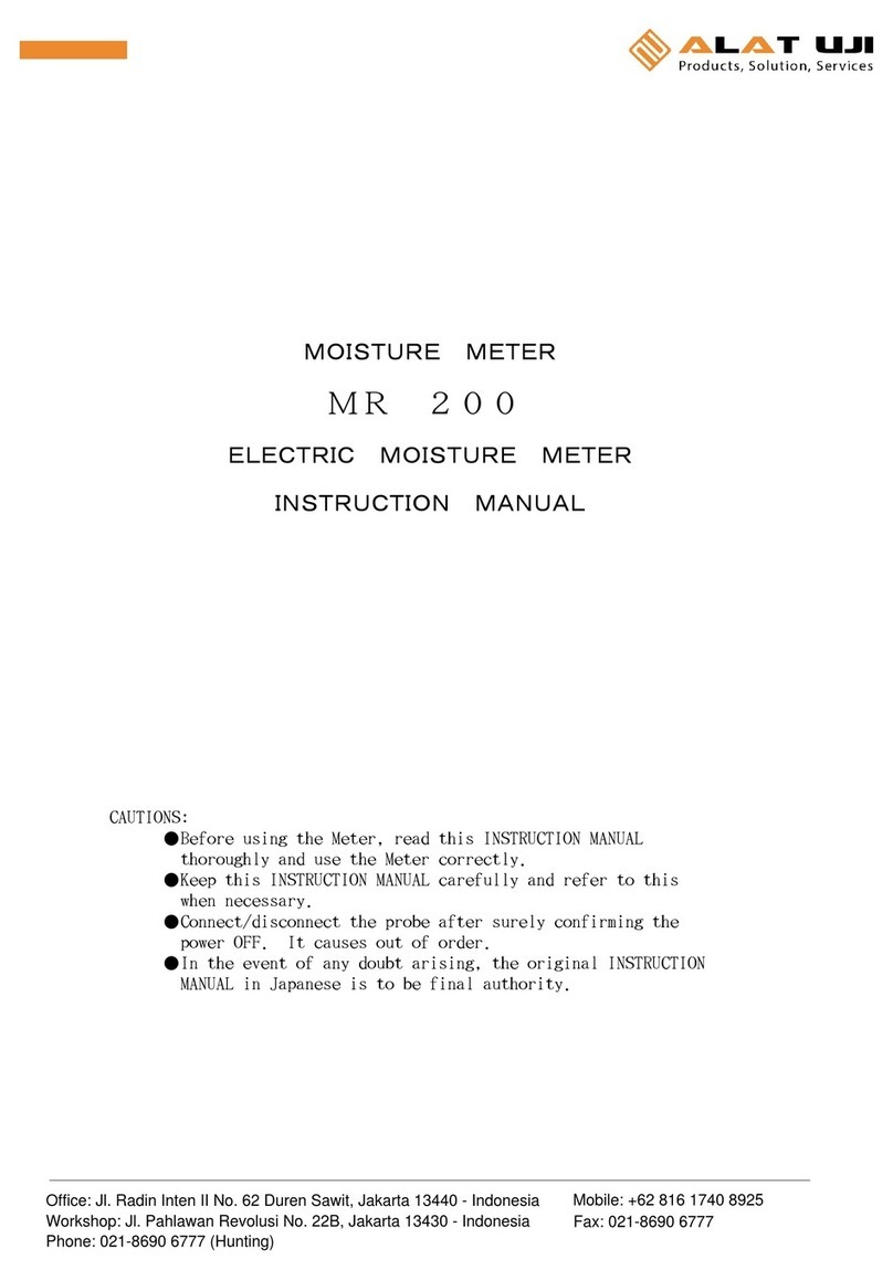
ALAT UJI MR-200 User manual

ALAT UJI

ALAT UJI MR-200 User manual

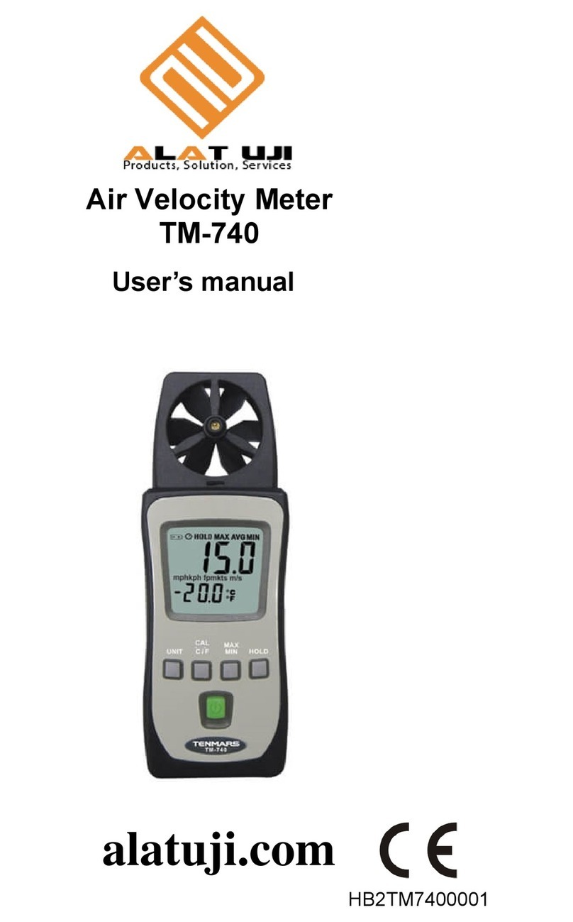
ALAT UJI TM-740 User manual

ALAT UJI

ALAT UJI TM-740 User manual

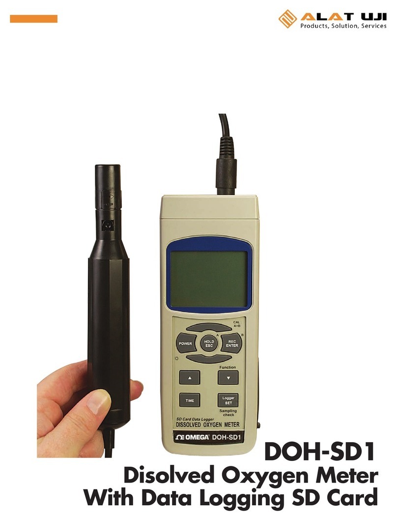
ALAT UJI OMEGA DOH-SD1 User manual

ALAT UJI

ALAT UJI OMEGA DOH-SD1 User manual

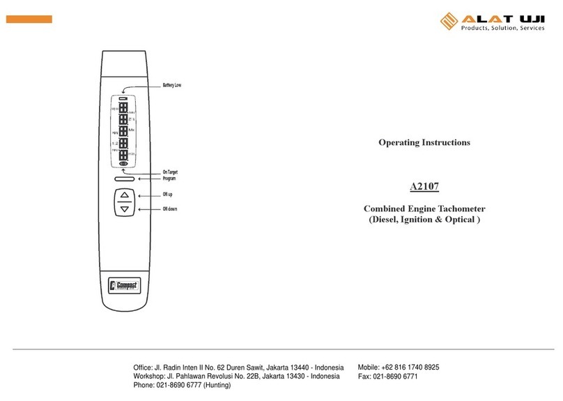
ALAT UJI A2107 User manual

ALAT UJI

ALAT UJI A2107 User manual

ALAT UJI TG-101 Instruction Manual

ALAT UJI

ALAT UJI TG-101 Instruction Manual

ALAT UJI M5-012 User manual

ALAT UJI

ALAT UJI M5-012 User manual

Popular Measuring Instrument manuals by other brands

Bahco BDACM1000 user manual

Bahco

Bahco BDACM1000 user manual

Juniper 4VETJ user manual

Juniper

Juniper 4VETJ user manual

Novasina nSens quick guide

Novasina

Novasina nSens quick guide

HVTest HTHL-200A manual

HVTest

HVTest HTHL-200A manual

PCE Instruments PCE-AQD 20 user manual

PCE Instruments

PCE Instruments PCE-AQD 20 user manual

QUARTA RADEX ONE user manual

QUARTA

QUARTA RADEX ONE user manual

Independence Evo CROSS 100 owner's manual

Independence

Independence Evo CROSS 100 owner's manual

Rover OMNIA 7000 user guide

Rover

Rover OMNIA 7000 user guide

Agilent Technologies 4155C user guide

Agilent Technologies

Agilent Technologies 4155C user guide

Kestrel 5700 Sportsman instruction manual

Kestrel

Kestrel 5700 Sportsman instruction manual

Garland M100G1AC user guide

Garland

Garland M100G1AC user guide

Sonoff TH R3 user manual

Sonoff

Sonoff TH R3 user manual

AETOOL GLOW PLUG ANALYSER user manual

AETOOL

AETOOL GLOW PLUG ANALYSER user manual

Reely RE-5631039 operating instructions

Reely

Reely RE-5631039 operating instructions

TESTO 405-V1 instruction manual

TESTO

TESTO 405-V1 instruction manual

SED 024.86.119 operating instructions

SED

SED 024.86.119 operating instructions

Elma Instruments Kewprove 3 user manual

Elma Instruments

Elma Instruments Kewprove 3 user manual

TDX MT1902 quick start guide

TDX

TDX MT1902 quick start guide

manuals.online logo
manuals.online logoBrands
  • About & Mission
  • Contact us
  • Privacy Policy
  • Terms and Conditions

Copyright 2025 Manuals.Online. All Rights Reserved.