Series AFS6000
Alba Fiber Systems Inc. Specifications are subject to change without notice. Page 4 9/14/13
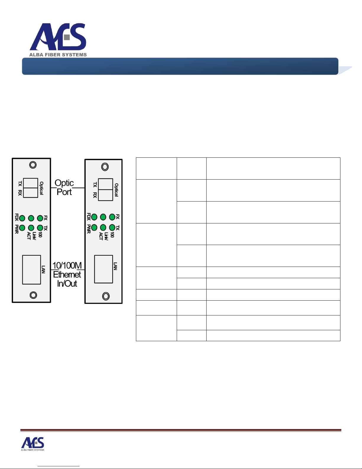
10/100MBPS ETHERNET MEDIA CONVERTER ON 1 OR 2 FIBERS
2.0 Fiber Installation Hints
Fiber Information
Alba Fiber Transmission Systems are manufactured with optical connector covers to keep them
from accumulating dirt. In addition to safety precautions, our manual also provide the following
guidelines when working with optical fibers.
Please maintain optical fiber connectors as clean as possible to reduce loss of optical
transmission output. Cleanliness is extremely important to proper operations.
1. Protect optical connectors by leaving the connector covers in place on unused fiber
connections and on the fiber tips themselves.
a. Personnel who remove and replace fiber connectors or fiber pigtails should be equipped
with a fiber cleaning kit. These are available as off-the-shelf items from a supplier of fiber
optic accessories.
b. Propyl Alcohol and lint-free tissue or cloth may be used to clean fiber connector tips.
c. Do not use rubbing alcohol mixed with water. This can cause additional spots.
d. Clean the fiber by pulling the connector tip across the tissue, then turn the connector 90
degrees and repeat it in a different spot on the tissue.
e. Don’t pull the fiber across and then push it back. This will put the dirt that was cleaned off
back on again.
f. Repeat the process on a dry, folded tissue.
2. When removing fiber cables from fiber system ports, it is good practice to clean them again.
3. Installer must pay attention to the bend radius of the fibers. A general rule is to have a 3-
inch (8cm) bend radius. A bend radius less than 3 inches may cause attenuation also known
as optical signal loss.
4. Installers of fiber equipment should be equipped with an Optical Light Source an Optical
Power Meter to measure the optical inputs and outputs in a system. These instruments are
available from Alba at great savings, especially to our customers. The use of these tools will
save much time and effort in getting optical communications links up and running. Properly
equipped and trained installers can quickly determine the source of any problems that occur.