IONODES ION-E100 User manual

DOCUMENT APPROVED FOR GENERAL DISTRIBUTION
ION-E100
User Manual
Version 1.7
InterTest, Inc • 303 Route 94 • Columbia, NJ 07832 • 908-496-8008 • [email protected] • www.intertest.com

Table of Contents
1BEFORE YOU BEGIN....................................................................................................................4
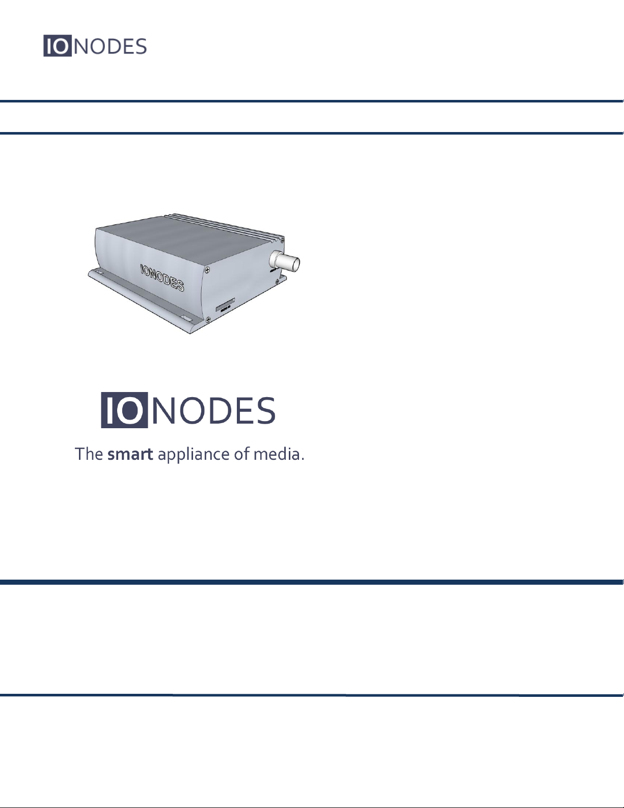
1.1 ABOUT THE ION-E100...............................................................................................................4
1.2 PARTS LIST ...............................................................................................................................5
2HARDWARE INSTALLATION .......................................................................................................6
2.1 EQUIPMENT INSTALLATION .........................................................................................................6
3CONNECTIONS..............................................................................................................................7
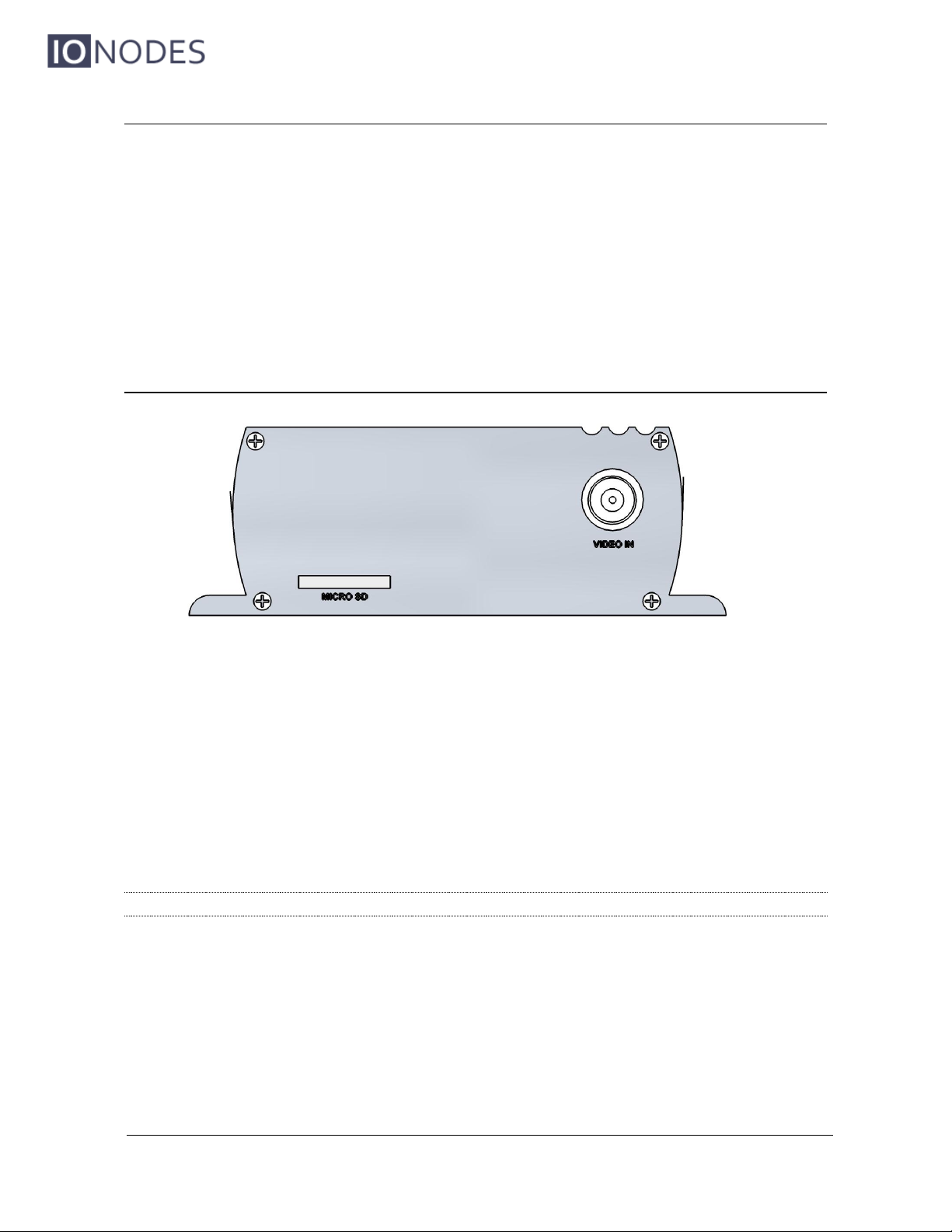
3.1 FRONT PANEL............................................................................................................................7
3.2 REAR PANEL .............................................................................................................................8
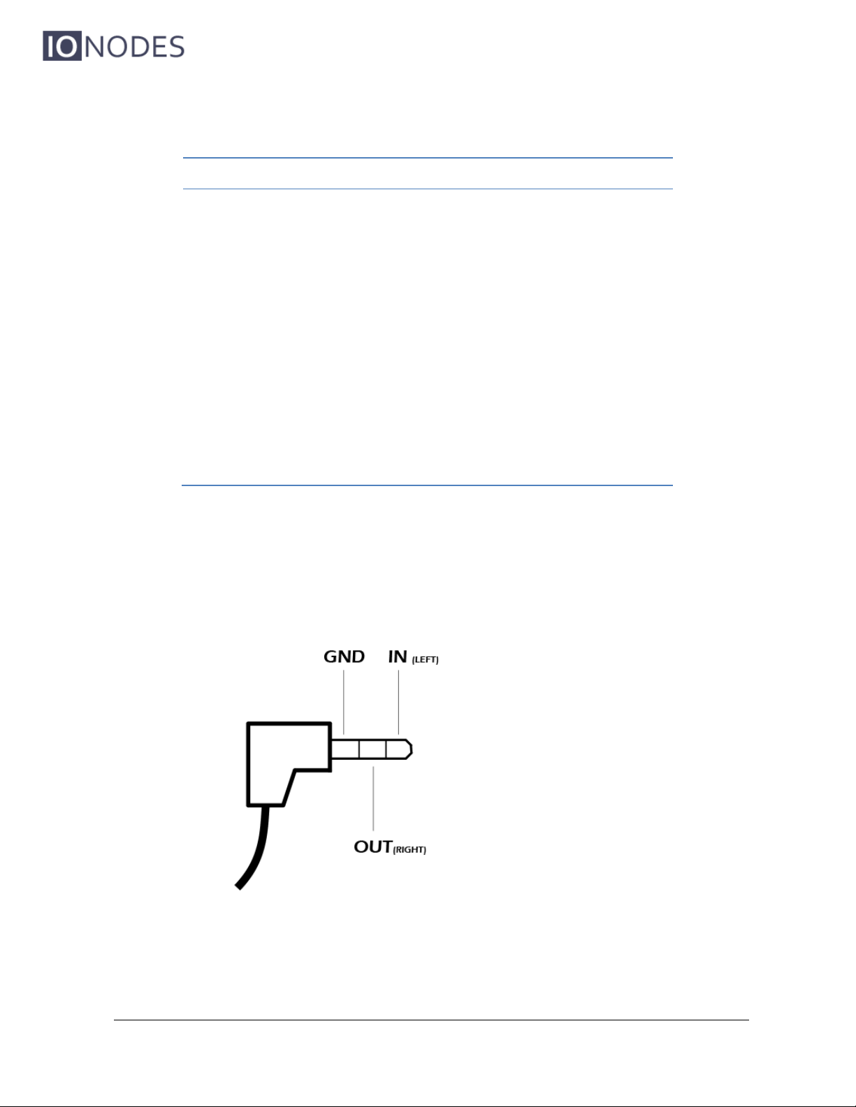
4SERIAL PORT CONNECTIVITY..................................................................................................11
5UNDERSTANDING LED STATUS...............................................................................................13
Normal Operation:.........................................................................................................................13
Special Operations:.......................................................................................................................13
6INITIAL SYSTEM CONFIGURATION ..........................................................................................14
6.1 NETWORK CONFIGURATION......................................................................................................14
6.2 USING THE ION-E100 WEB APPLICATION .................................................................................18
Setting up the NTP server.............................................................................................................19
Configuring Video Parameters......................................................................................................19
7PERFORMING A FIRMWARE UPDATE .....................................................................................21
7.1 BATCH FIRMWARE UPDATE ......................................................................................................22
8RECORDING ON THE EDGE ......................................................................................................25
8.1 CONFIGURATION ......................................................................................................................25
8.2 AUDIO RECORDING ..................................................................................................................28
8.3 RETRIEVAL /MANAGEMENT OF VIDEO CLIPS .............................................................................28
8.3.1 Displaying Clips .................................................................................................................29
8.3.2 Downloading Clips.............................................................................................................29
8.3.3 Locking And Unlocking Clips.............................................................................................29
8.3.4 Deleting Clips.....................................................................................................................30
9POINT TO POINT CONNECTIONS .............................................................................................31
InterTest, Inc • 303 Route 94 • Columbia, NJ 07832 • 908-496-8008 • [email protected] • www.intertest.com

ION-E100 –User manual
Page 3 of 36
ANNEX A –CONFIGURATION PARAMETER REFERENCE............................................................32
ANNEX B –TROUBLESHOOTING GUIDE ........................................................................................35
ANNEX C –STATEMENT LIMITED WARRANTY..............................................................................36
InterTest, Inc • 303 Route 94 • Columbia, NJ 07832 • 908-496-8008 • [email protected] • www.intertest.com

ION-E100 –User manual
Page 4 of 36
1 Before you begin
1.1 About the ION-E100
The ION-E100 single port encoder delivers high quality H.264 video encoding to the video
surveillance market. It is an embedded, high-performance digital video encoder, capable of
encoding an analog camera input using multiple profiles at a combined 90 images per second
(NTSC/PAL) at 4CIF resolution.
Embedding support for networked API’s, the ION-E100 can be integrated into a networked video
management system allowing for centralized monitoring and management in a scalable and
expandable IP surveillance system. Contact IONODES for a list of supported VMS systems.
The high-performance encoding capability of the ION-E100 offers a cost-effective way to service
existing analog cameras while providing the benefits of video over IP networks.
The ION-E100 provides innovative configuration options and tools that can significantly
decrease the amount of time and effort required to deploy a unit. Using web-based configuration
tools, users can easily and remotely manage all aspects of the appliance.
To support high-performance encoding, while keeping the total cost of ownership within budget
constraints, the ION-E100 uses highly efficient dual stream H.264 compression and supports an
optional third MJPEG stream.
Advanced features, such as “edge-recording” and “video analytics” allow you to extend usage of
the ION-E100 well into the future.
InterTest, Inc • 303 Route 94 • Columbia, NJ 07832 • 908-496-8008 • [email protected] • www.intertest.com

ION-E100 –User manual
Page 5 of 36
1.2 Parts List
Qty Description
1 ION-E100 appliance
1 Terminal block socket (P/N Weidmuller 1727660000 or 1727580000)
Note: When unpacking, inspect the shipment box and appliance to identify any possible
damages due to shipping. Make sure all items have been delivered and that no
items are missing. Contact your Ionodes representative should you find any damag-
es or defects.
Note: The product serial number label helps the Ionodes product support team identify
your device and its factory configuration in the event that your ION-E100 or its com-
ponents require service. The label is attached on the underside of the enclosure.
.
InterTest, Inc • 303 Route 94 • Columbia, NJ 07832 • 908-496-8008 • [email protected] • www.intertest.com

ION-E100 –User manual
Page 6 of 36
2 Hardware Installation
2.1 Equipment Installation
The ION-E100 can be placed on a flat surface, such as a desktop, or mounted via the available
mounting holes.
When installing the ION-E100, position the unit to allow for cable clearance at the front and rear
of the unit. Make sure that minimal air flow is provided to the unit.
The ION-E100 can be mounted to various mounting structures via the available mounting holes.
Note that mounting screws are not shipped with the device.
Warning: Be careful not to damage the enclosure when using mounting screws.
InterTest, Inc • 303 Route 94 • Columbia, NJ 07832 • 908-496-8008 • [email protected] • www.intertest.com

ION-E100 –User manual
Page 7 of 36
3 Connections
Familiarize yourself with the ION-E100 front and rear panels before connecting any equipment to
the unit. The ION-E100 offers a single analog video input and associated I/Os and audio
connections.
3.1 Front Panel
VIDEO IN
BNC connector interface for video input source (NTSC / PAL).
MICRO SD (optional)
Micro SD connector available for edge recording capability. Please insert a formatted
(FAT) micro SD card to enable associated functionality.
Note: A micro SD card is not provided with the device.
InterTest, Inc • 303 Route 94 • Columbia, NJ 07832 • 908-496-8008 • [email protected] • www.intertest.com

ION-E100 –User manual
Page 8 of 36
3.2 Rear Panel
Terminal Bloc Header
This header connector is used to connect the supplied Terminal Bloc Socket which
provides the interface to serial port, I/O and power connections.
Below is a detailed view of this Terminal Bloc Socket:
Terminal Bloc
Header
RL I1 Rx+ Tx+ 12v
RL I2 Rx- Tx- GND
Relay Output
Digital Input Pins #1 & #2
Receiver pair for serial communication (4 wire RS-422 or RS-485)
Transmitter pair for serial communication (4 wire RS-422 or RS-485)
12V power source
InterTest, Inc • 303 Route 94 • Columbia, NJ 07832 • 908-496-8008 • [email protected] • www.intertest.com

ION-E100 –User manual
Page 9 of 36
The pin out description of the Terminal Bloc Socket is as follows:
Number
Description
Direction
1
RL (Relay)
Out
2
RL (Relay)
Out
3
I1 (Digital Input 1)
In
4
I2 (Digital Input 2)
In
5
RX+
In
6
RX-
In
7
TX+
Out
8
TX-
Out
9
12V supply
In
10
Ground
-
AUDIO IN / OUT
3.5 mm jack which can be used to connect both an audio input and an audio output
source. The stereo channel provided by this connector exposes one channel for the
audio input and the other for the audio output.
STATUS
The system status LED is a bi-color (Yellow - Orange) LED providing detailed
InterTest, Inc • 303 Route 94 • Columbia, NJ 07832 • 908-496-8008 • [email protected] • www.intertest.com

ION-E100 –User manual
Page 10 of 36
information on the current state of the device.
ETHERNET / PoE
This is the ION-E100 network port. Please use a straight RJ45 (cat. 5 or 6) network
cable. The ION-E100 accepts a Power-Over-Ethernet (PoE) compliant power source if
needed.
RESET
The reset button can be used to perform a hardware reset, or to perform a complete
reset to default settings of the device’s configuration parameters.
InterTest, Inc • 303 Route 94 • Columbia, NJ 07832 • 908-496-8008 • [email protected] • www.intertest.com

ION-E100 –User manual
Page 11 of 36
4 Serial Port Connectivity
Many devices (PTZ keyboards, PTZ cameras, etc.) use RS-422/485 protocols for
communicating with other equipment. These protocols are standards for binary data exchange
between DTE and DCE equipments.
To connect serial equipment to an ION-E100 using RS-422/485 4-wire configuration, use the
following steps:
1. Connect twisted pair cables to the Terminal Bloc Socket located on the front panel of the
device. Connect to Tx+, Tx-, Rx+, Rx-and GND.
2. Select the desired operation mode (RS-422 4-wire, RS-485 2-wire or RS-485 4-wire)
using the devices web interface or external VMS interface.
3. To ensure proper connection between RS-422 4-wire or RS-485 4-wire serial equipment
and the ION-E100, use the following scheme:
Equipment Serial Port
ION-E100 Serial Port
TX+
RX+
TX-
RX-
RX+
TX+
RX-
TX-
GND
GND
To connect serial equipment to an ION-E100 using RS-485 2-wire configuration, use the
following steps:
5
InterTest, Inc • 303 Route 94 • Columbia, NJ 07832 • 908-496-8008 • [email protected] • www.intertest.com

ION-E100 –User manual
Page 12 of 36
1. To create the negative data signal, please connect Rx-and Tx-pins together on the
Terminal Bloc Socket.
2. To create the positive data signal, please connect Rx+ and Tx+ pins together on the
Terminal Bloc Socket.
3. To ensure proper connection between RS-485 2-wire serial equipment and the ION-
E100, use the following scheme:
Equipment Serial Port
ION-E100 Serial Port
Data +
Data +
Data -
Data -
GND
GND
InterTest, Inc • 303 Route 94 • Columbia, NJ 07832 • 908-496-8008 • [email protected] • www.intertest.com

ION-E100 –User manual
Page 13 of 36
5 Understanding LED Status
The following describes the system status LED mappings of the ION-E100:
Normal Operation:
Operating system boot up –LED is steady orange (max. 30 seconds)
Internal application startup –LED is flashing orange (2 second interval)
ION-E100 system ready –LED is steady yellow
Media streaming –LED is flashing yellow (1/2 second interval)
Special Operations:
Identify command received –LED is flashing orange/yellow
Hardware reload default settings –LED is flashing rapidly red/yellow
Software watchdog is rebooting the appliance –LED is flashing rapidly red
Firmware update in progress –LED is flashing slowly red/yellow
Note: Under normal operation, the ION-E100 takes up to 1-2 minutes to boot up.
InterTest, Inc • 303 Route 94 • Columbia, NJ 07832 • 908-496-8008 • [email protected] • www.intertest.com

ION-E100 –User manual
Page 14 of 36
6 Initial System Configuration
For initial set-up, the ION-E100 needs to be configured prior to using it with your network video
management system. In most cases, only network configuration will be required. Since not all
ION-E100 parameters can be controlled via networked video management systems, advanced
parameters may need to be set-up as well through the ION specific software tools.
The initial configuration can be done locally on the ION-E100 using a laptop directly connected
to the device’s network port, or remotely over the network.
6.1 Network Configuration
By factory default, the ION-E100 is configured in DHCP. If you are not using a DHCP server it
will automatically allocate itself an APIPA (Automatic Private IP Addressing) address in the
range 169.254.0.1 to 169.254.255.254 with subnet mask 255.255.0.0.
Initial device network configuration is done via the IonConfigTool (ICT), a tool provided by
IONODES and that can be found on the company’s web site.
The ICT plays 5 important roles:
1. Discovery of all ION-E100 and other ION devices on the network
2. Remote configuration of the IP address and subnet mask
3. Identify an ION device by flashing the LED (orange/yellow)
4. Batch firmware upgrade of all common ION devices
5. Access to the web based ION management application
InterTest, Inc • 303 Route 94 • Columbia, NJ 07832 • 908-496-8008 • [email protected] • www.intertest.com

ION-E100 –User manual
Page 15 of 36
Once your device is installed on your network and powered up, launch ICT from any computer
on the network and the following window will be displayed:
The ICT supports 2 ways to discover a device. The first way doesn’t need any configuration and
uses the Bonjour discovery protocol. In order to be able to discover a device via Bonjour, the
network must support multicast delivery.
If it is not the case, you can use the second way, which is the Unicast Discovery. The Unicast
Discovery can be configured by using the “Unicast Discovery” configuration form. This
configuration form is available via the Admin / Unicast Discovery menu option.
InterTest, Inc • 303 Route 94 • Columbia, NJ 07832 • 908-496-8008 • [email protected] • www.intertest.com

ION-E100 –User manual
Page 16 of 36
To configure the Unicast Discovery, add one or more IP address ranges. The Unicast Discovery
tries to reach a device at a specific IP address in the configured ranges. The discovery can be a
long process if the range of IP addresses is huge and the device is at the end of the range. To
accelerate the discovery, add several small ranges of IP addresses.
The ping timeout option can be increased for a high latency network.
The ICT will display as many devices as it discovers on the network.
InterTest, Inc • 303 Route 94 • Columbia, NJ 07832 • 908-496-8008 • [email protected] • www.intertest.com

ION-E100 –User manual
Page 17 of 36
If no DHCP server was able to assign an IP address to an ION-E100, it will appear in the ICT
device list with an APIPA address (169.254.*.*). If an ION-E100 displays an APIPA address it
must be configured with a valid IP address before it can be remotely configured by selecting the
‘’Assign IP address’’ from the selection list and configuring the TCP/IP settings.
InterTest, Inc • 303 Route 94 • Columbia, NJ 07832 • 908-496-8008 • [email protected] • www.intertest.com

ION-E100 –User manual
Page 18 of 36
Once the IP information is set, the Silverlight web application served by the ION-E100 can be
launched from the ICT or directly in your web browser by typing the device’s IP address in the
address bar. You can start to use your networked video management system for final system
configuration or you can configure advanced parameters using the ION-E100’s web based
management.
6.2 Using the ION-E100 Web Application
When entering the Web Application, you will be asked a username and password. The default
user name and password is ‘admin’. The following window will be displayed:
The following parameters may need to be programmed before using the unit:
1. An NTP time server address
2. Video encoder streams
InterTest, Inc • 303 Route 94 • Columbia, NJ 07832 • 908-496-8008 • [email protected] • www.intertest.com

ION-E100 –User manual
Page 19 of 36
Setting up the NTP server
Under the Configuration section, select the Network tab and set the proper NTP server
address under the NTP Configuration header.
Configuring Video Parameters
You may disable any of the three (3) video encoder streams (Primary H.264, Secondary H.264
and MJPEG). All other video parameters should be configured within your NVM system.
Note: We recommend disabling the MJPEG codec if you do not intend on using this codec
within your application. This will avoid turning on this stream by inadvertence and
possibly affecting the performance of the H.264 codecs.
InterTest, Inc • 303 Route 94 • Columbia, NJ 07832 • 908-496-8008 • [email protected] • www.intertest.com

ION-E100 –User manual
Page 20 of 36
InterTest, Inc • 303 Route 94 • Columbia, NJ 07832 • 908-496-8008 • [email protected] • www.intertest.com
Table of contents
Other IONODES Media Converter manuals

IONODES
IONODES ION-R100 User manual

IONODES
IONODES ION-R100S User manual

IONODES
IONODES ION-R100S User manual

IONODES
IONODES ATOMAS-IOT-DUAL User manual

IONODES
IONODES ATOMAS-DUO-HDMI User manual

IONODES
IONODES ION-R100S User manual

IONODES
IONODES ION-R200 User manual

IONODES
IONODES ION-E100-HD User manual

IONODES
IONODES ATOMAS-MINI User manual