IFM DP1223 User manual

Operating instructions
Converter IO-Link / 2 x 0...10 V
DP1223
80272879 / 00 02 / 2020
UK

2
Contents
1 Preliminary note...................................................................................................4
1.1 Symbols used ................................................................................................4
1.2 Warnings used...............................................................................................4
2 Safety instructions ...............................................................................................5
3 Functions and features ........................................................................................6
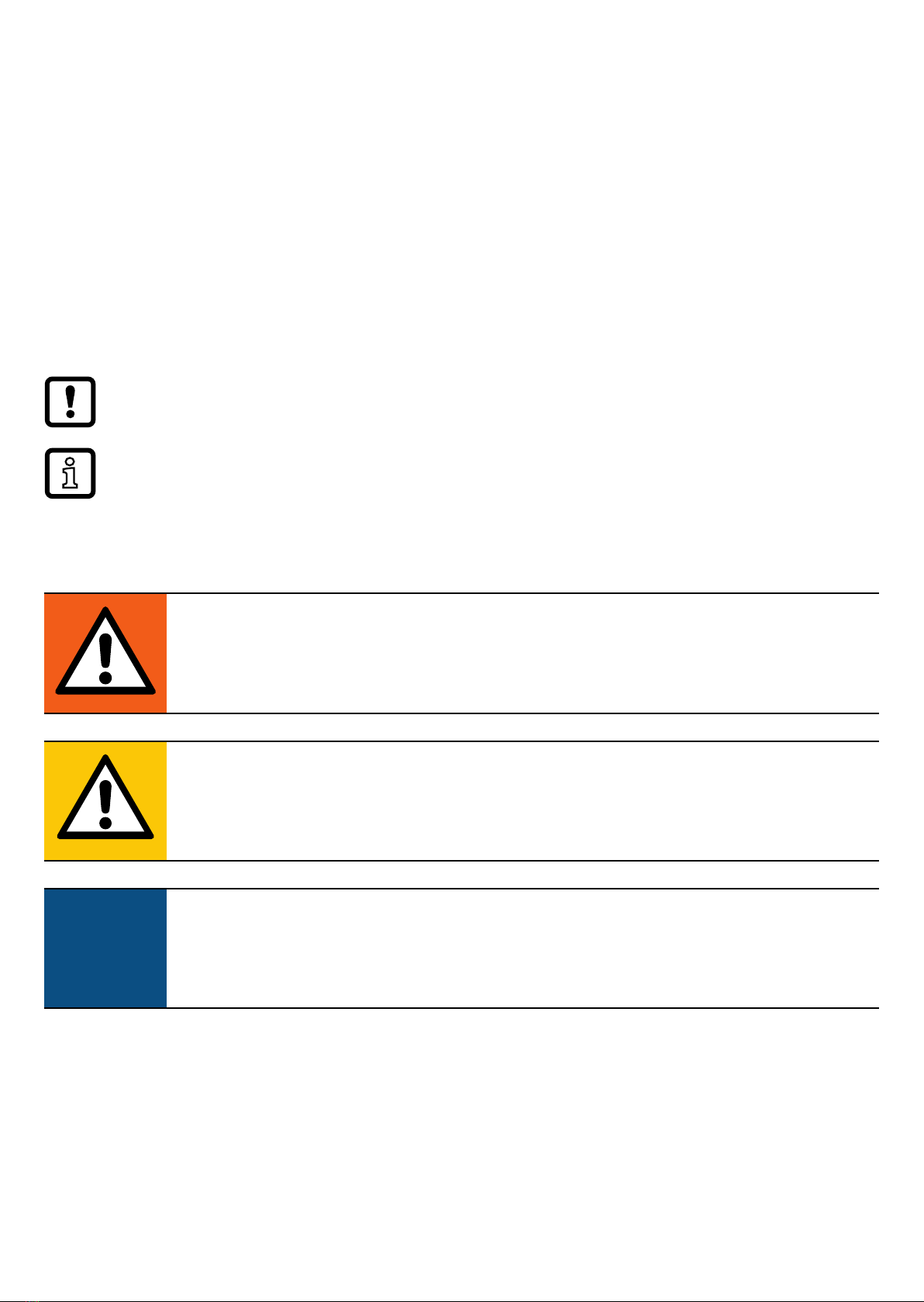
3.1 Block diagram................................................................................................6
3.2 General application and functionality.............................................................6
3.3 Application as an IO-Link device ...................................................................7
3.3.1 General information ..............................................................................7
3.3.2 IO Device Description (IODD) ..............................................................7
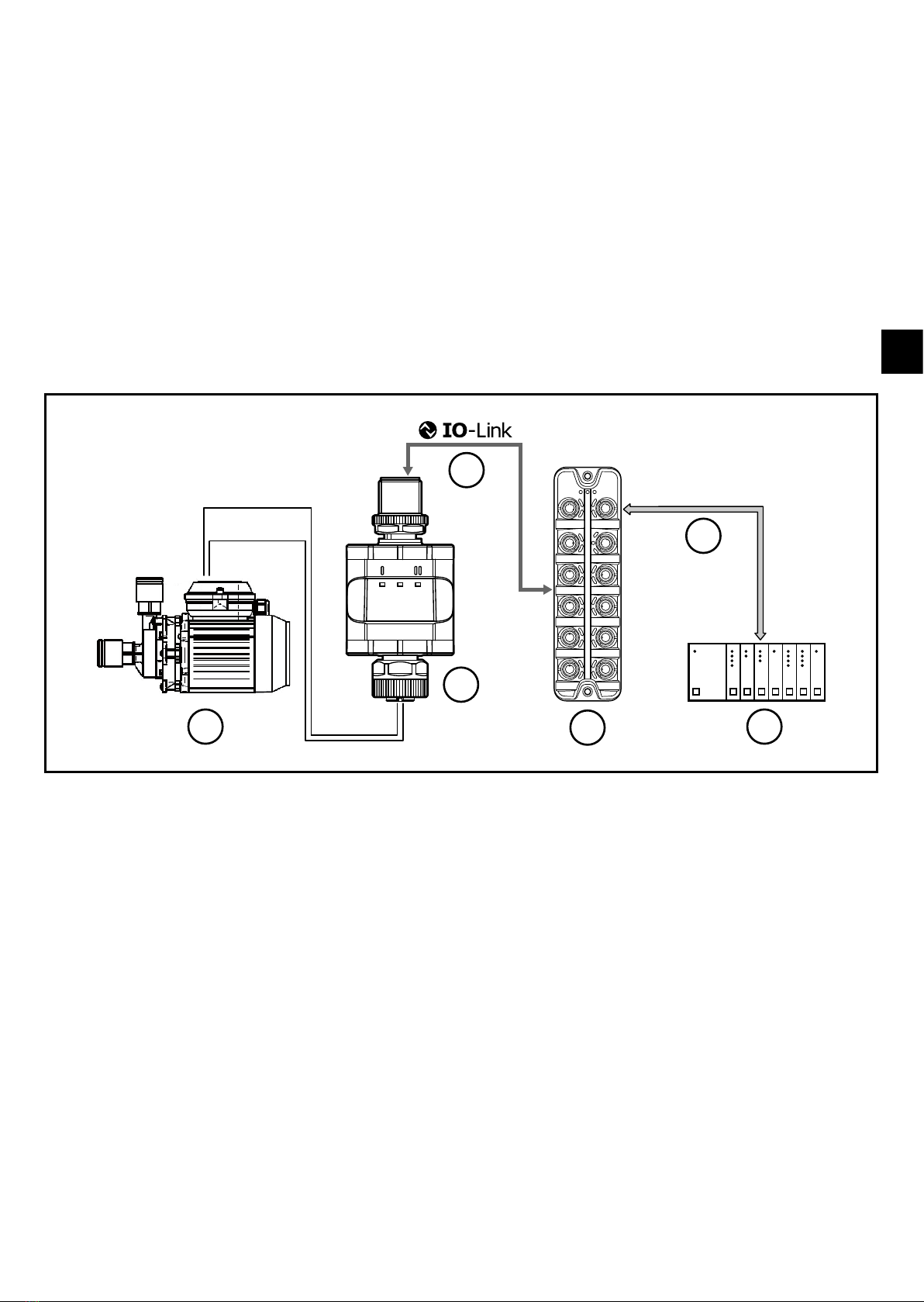
4 Operating and display elements ..........................................................................8
4.1 LEDs..............................................................................................................8
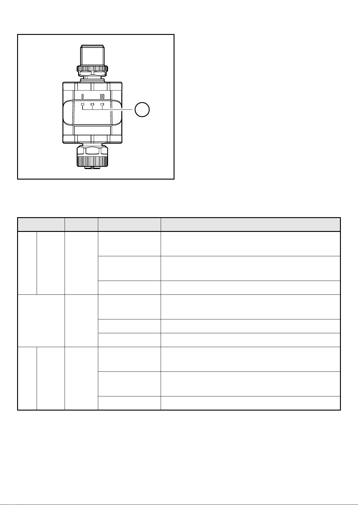
4.1.1 Visualisation of the voltage value at the output ...................................9
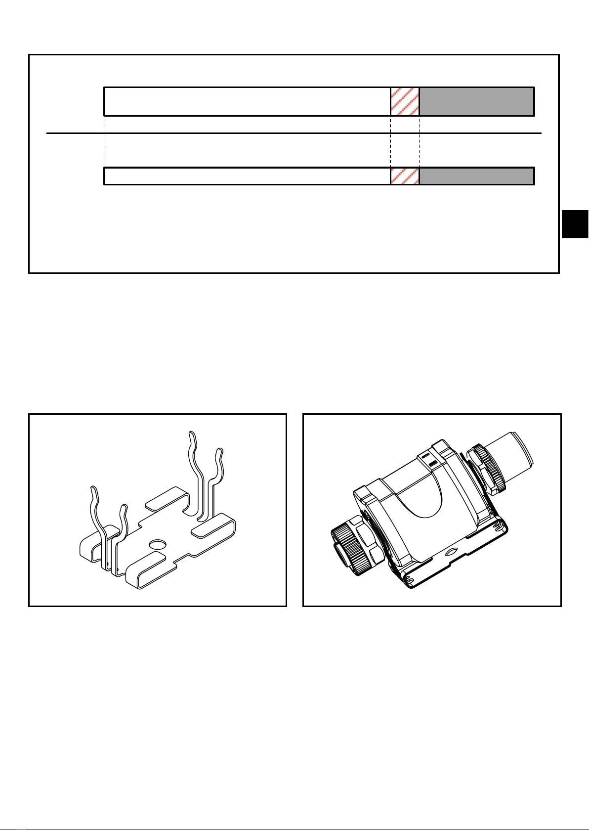
5 Installation............................................................................................................9
6 Electrical connection..........................................................................................10
6.1 Maximum length of the connection cables ..................................................12
7 Operation ..........................................................................................................12
8 Parameters ........................................................................................................12
8.1 Parameters via IO-Link................................................................................12
8.1.1 Application-specific tag .......................................................................12
8.1.2 Plant identification code......................................................................12
8.1.3 Location identification code ................................................................12
9 Parameter setting ..............................................................................................12
10 Scale drawing ..................................................................................................13
11 Technical data ..................................................................................................14
11.1 IO-Link device............................................................................................14
11.2 Approvals/standards ..................................................................................15
12 Troubleshooting ...............................................................................................15
13 Maintenance, repair and disposal....................................................................15

3
UK
13.1 Maintenance ..............................................................................................15
13.2 Cleaning the housing surface ....................................................................15
13.3 Repair ........................................................................................................15
13.4 Disposal.....................................................................................................15
This document is the original instructions.

4
1 Preliminary note
Technical data, approvals, accessories and further information at
www.ifm.com.
1.1 Symbols used
►Instructions
> Reaction, result
[…] Designation of keys, buttons or indications
→Cross-reference
Important note
Non-compliance may result in malfunction or interference.
Information
Supplementary note.
1.2 Warnings used
WARNING!
Warning of serious personal injury.
Death or serious irreversible injuries may result.
CAUTION!
Warning of personal injury.
Slight reversible injuries may result.
ATTENTION!
Warning of damage to property

5
UK
2 Safety instructions
• The device described is a subcomponent for integration into a system.
The manufacturer is responsible for the safety of the system. The system
manufacturer undertakes to perform a risk assessment and to create a
documentation in accordance with legal and normative requirements to be
provided to the operator and user of the system. This documentation must
contain all necessary information and safety instructions for the operator,
the user and, if applicable, for any service personnel authorised by the
manufacturer of the system.
• Read this document before setting up the product and keep it during the entire
service life.
• The product must be suitable for the corresponding applications and
environmental conditions without any restrictions.
• Only use the product for its intended purpose (→ 3 Functions and features).
• If the operating instructions or the technical data are not adhered to, personal
injury and/or damage to property may occur.
• In case of malfunctions of the unit, please contact the manufacturer. Tampering
with the unit is not allowed.
• Installation, electrical connection, set-up, programming, configuration, operation
and maintenance of the product must be carried out by personnel qualified and
authorised for the respective activity.
• Protect units and cables against damage.

6
3 Functions and features
3.1 Block diagram
DP1223
OUT2 (analogue)
OUT1 (analogue)
IO-Link C/Q
Inputs/outputs of the device
3.2 General application and functionality
The device is used for the control of a connected actuator or another device
with analogue input (0...10 V). It is not suited for environments with particular
requirements on mechanical stability (e.g. shock/vibration). The device has two
analogue voltage outputs.
The device is intended for indoor use only.
Observe the operating conditions (→ 11 Technical data).
The device works as an "IO-Link / analogue converter".
The voltage values to be provided can be set via IO-Link communication
using IO-Link tools or a PLC.

7
UK
3.3 Application as an IO-Link device
3.3.1 General information
The device has an IO-Link communication interface that requires an IO-Link-
capable module (IO-Link master).
The IO-Link interface allows direct access to the process and diagnostic data and
enables setting of the parameters of the unit during operation.
You will find further information about IO-Link and all necessary information about
the required IO-Link hardware and software at:
www.ifm.com/gb/io-link.
3
2
0...10 V
24 V DC
1
Fieldbus
4
5
6
Application example with IO-Link master
1: Analogue actuator
2: Converter IO-Link / 2 x 0...10 V
3: Fully bidirectional IO-Link communication
- Remote parameter setting: reading and
changing the parameter setting.
4: IO-Link master
5: Fieldbus (e.g. Probus, Pronet etc.)
6: PLC
3.3.2 IO Device Description (IODD)
You will find the IODDs necessary for the configuration of the IO-Link device and
detailed information about process data structure, diagnostic information and
parameter addresses at:
www.ifm.com

8
4 Operating and display elements
1
1: LEDs
4.1 LEDs
LED Colour Status Description
I OUT1 yellow on Analogue value in the standard range:
0...100 % (0...10 V)
flashing (2 Hz) Analogue value in the range:
100...110 % (10...11 V)
flashing (5 Hz) Short circuit or overload at the output
Power green on Voltage supply OK.
Device in operating mode.
flashing (5 Hz) Device supply undervoltage
off Voltage supply off.
II OUT2 yellow on Analogue value in the standard range:
0...100 % (0...10 V)
flashing (2 Hz) Analogue value in the range:
100...110 % (10...11 V)
flashing (5 Hz) Short circuit or overload at the output
Error signals and diagnostics (→ 12 Troubleshooting)

9
UK
4.1.1 Visualisation of the voltage value at the output
0 10 11 [V]
I
O-Link
process
data
0
...
10000
10001
...
11000
[mV]
5 Installation
The M12 connecting parts must not be mechanically stressed when in use in
the application. Depending on the operating conditions, the device is also to be
protected against mechanical stress, e.g. shock or vibration. If required, the device
can be fixed with a mounting clip.
Mounting clip (fasten with M4 screw or
cable ties)
Mounting clip with display attached
The mounting clip is not supplied with the device.
More information about the available accessories at:
www.ifm.com

10
6 Electrical connection
The unit must be connected by a qualified electrician.
The national and international regulations for the installation of electrical
equipment must be adhered to.
Voltage supply according to SELV, PELV.
►Protected circuits
Potential M12 connector
①
Circuit breaker
L+ / supply voltage Pin 1 ≤ 2 A
C/Q IO-Link (if not protected
via IO-Link master)
Pin 4 ≤ 2 A
Required tripping characteristic of the fuses:
Tfuse ≤ 120 s at max. 6.25 A (fire protection)
►Alternatively supply the device via a limited energy circuit according to
IEC 61010-1 or class 2 according to UL1310.
CAUTION!
Input current is not limited.
> No fire protection
►Protected circuits
For use in USA and Canada: For connecting the device and the IO-Link devices
use UL certificated cables of category CYJV 2/7/8 having suitable ratings.
►Disconnect power.
►Connect the device according to the table below.

11
UK
2
1
43
2 1
3
1 2
4
5
Pin 4-pole M12 make connector ①
1 L+ / supply voltage
2 not used
3 L- / supply voltage
4 C/Q IO-Link
Pin 5-pole M12 female connector ②
1 L+
2 0...10 V analogue output 2
3 L-
4 0...10 V analogue output 1
5 not used
1: IO-Link side
2: Actuator side
The device must not be externally supplied via the 5-pole M12 output
socket ②.
Always use the provided connection cables to connect other devices to the
converter.
Also see application examples (→ 3 Functions and features)
Tighten the M12 connectors firmly to ensure the protection rating.
Protection rating (→ 11 Technical data).
►Connect the device as required (arrow shows the position of the coding).
►Tighten coupling nut.
Tightening torque: min. 0.6 Nm (tightening by hand), max. 1.5 Nm (using
a torque wrench)
►For removal, loosen the coupling nut and simultaneously press the
connector against the device.
►If used in harsh environments, further tighten the coupling nut by
another notch using a torque wrench (across the flats 14).

12
6.1 Maximum length of the connection cables
With IO-Link communication on the master side: 20 m.
All cables must be provided with a strain relief approx. 200 mm behind the
connectors.
7 Operation
The device provides the output signals according to the process data set via IO-
Link.
8 Parameters
8.1 Parameters via IO-Link
8.1.1 Application-specific tag
Customer-specific application description, max. 32 characters long.
Value: “ *** ” / can be freely defined by the customer
8.1.2 Plant identification code
Customer-specific plant identification code, max. 32 characters.
Value: “ *** ” / can be freely defined by the customer
8.1.3 Location identification code
Customer-specific location identification code, max. 32 characters.
Value: “ *** ” / can be freely defined by the customer
9 Parameter setting
During parameter setting, the device remains in the operating mode.
It continues its monitoring functions with the existing parameters until the
parameter setting has been completed.

13
UK
10 Scale drawing
Original Scale Drawing (MTD)
EPS Source
Product Scale Drawing
Frame Size: 80 mm x 49,5 mm
P_MZ_e200_0100
31
24
30
M12
x
1
M12
x
1
63
1
31
24
30
M12
x
1
M12
x
1
63
1
Dimensions [mm]

14
11 Technical data
Operating voltage DC [V] 18...30
Nominal voltage DC [V] 24
Current consumption [mA] 300
Number of analogue outputs 2
Analogue output (voltage) [V] 0...10
Extended voltage range [V] 0...11
Min. load resistor [Ω] 2000
Accuracy [% FS] 0.25
Protection rating IP 67*
Degree of soiling 2
Ambient temperature [°C] -25…70
Storage temperature [°C] -25…70
Max. perm. relative humidity [%] 90 (31 °C)
linearly decreasing to 50 (40 °C)
non condensing
Maximum operating altitude [m] 4000 above sea level
Connectors M12 connector, 4-pole
M12 socket, 5-pole
*) With threaded M12 connectors tightened as described
(→ 6 Electrical connection)
IP class was not evaluated by UL.
11.1 IO-Link device
Transmission type COM2 (38.4 kbaud)
IO-Link revision 1.1
SDCI standard IEC 61131-9
IO-Link device ID 614 d / 00 02 66 h
SIO mode no
Required master port type A/B
Process data analogue OUT: 2
Process data binary 0
Min. process cycle time [ms] 3.6

15
UK
11.2 Approvals/standards
EU declarations of conformity, approvals etc. can be downloaded at:
www.ifm.com
12 Troubleshooting
LED Status Error Troubleshooting
I flashing (5
Hz)
Short circuit or
overload at the output
Check/correct connection cables and
connections at the output (→ 6).
Power flashing (5
Hz)
Supply voltage too low. Check/correct the supply voltage (→ 6)
and (→ 11).
off No supply voltage Check/correct the supply voltage (→ 6)
and (→ 11).
II flashing (5
Hz)
Short circuit or
overload at the output
Check/correct connection cables and
connections at the output (→ 6).
13 Maintenance, repair and disposal
13.1 Maintenance
The unit is maintenance-free.
13.2 Cleaning the housing surface
►Disconnect the device.
►Clean the device from dirt using a soft, chemically untreated and dry cloth.
Micro-fibre cloths without chemical additives are recommended.
13.3 Repair
The device must only be repaired by the manufacturer.
►Observe the safety instructions.
13.4 Disposal
►Dispose of the device in accordance with the national environmental
regulations.
Table of contents
Other IFM Media Converter manuals

IFM
IFM Efector 400 RM7 Series Application guide

IFM
IFM E70354 User manual

IFM
IFM TP323 Series User manual

IFM
IFM RM8004 Application guide

IFM
IFM RM8 Series User manual

IFM
IFM E43406 User manual

IFM
IFM RN6065 User manual

IFM
IFM Efector 400 RU User manual

IFM
IFM RM8 Series Application guide

IFM
IFM DP1222 User manual