Alberici VANGUARD PL User manual

VANGUARD
TOPPER LIGHT
Available models:
VANGUARD PL (artwork enhanced by L.e.d. back
lighting),
with either chrome or black front frame; upon
re uest burnished frame available.
VANGUARD PL Rainbow (iridescent plexy
engraving),
with either chrome or black front frame;
upon re uest burnished frame available.
Any version can be chosen either with multicolour
RGB, or blue, or white light.
The onboard control set of the RGB versions allows
to switch from the mixed colours patterns to single
colour patterns (red, or blue, or green, or white).
VANGUARD NEON (artwork enhanced by L.e.d.
back lighting),
with either chrome or black front frame;
upon re uest burnished frame available.
VANGUARD NEON Rainbow (iridescent plexy
engraving),
with either chrome or black front frame;
upon re uest burnished frame available.
Any version can be chosen either with multicolour
RGB or white light.
The onboard control set of the RGB versions allows
to switch from the mixed colours patterns to single
colour patterns (red, or blue, or green, or white).
TECHNICAL DATA
Power supply 12V c , an 5 V c
Current raw 500 mAmp
Artwork Le s luminous power 280 Lumen
Bezel LEDs luminous power 600 Lumen
ISTRUZIONI
INSTALLAZIONE
VANGUARD,
ENG
, 1 di 6
VANGUARD
TOPPER LIGHT
Instructions
Rev. 2.3 IT

THE SET CONTAINS
A. Vanguard Topper Light
B. Standard adapter for r=441mm dome
C. Adapter for r=222mm dome
D. Adapter for flat shelf
E. tool for fixation from inside the dome
F. bar for fixation from outside the dome
G. n° 2 screws Ø 2,9 x 9,5 for fixing bar
TOOLS FOR FASTENING
ISTRUZIONI
INSTALLAZIONE
VANGUARD
ENG
, 2 di 6
MOUNTING FROM THE INSIDE OF THE DOME (NO NEED TO
OPEN THE MACHINE):
USE BAR
F
AND RELEVANT SCREWS
G
TO FASTEN THE
TOPPER TO THE PREVIOUSLY MOUNTED SUPPORT .
MOUNTING FROM THE INSIDE OF THE DOME:
USE TOOL
E
TO FASTEN THE TOPPER TO THE PREVIOUSLY
MOUNTED SUPPORT.
D
C
A
F
E
F
E
B

PROGRAMMING BEZEL LED COLOURS AND BRIGHTNESS
Lay the topper face downside. Remove the 6 screws placed along the rear perimetre as
well as the 2 screws located in the stem rear face. Rotate the topper face up, lift up the
front bezel and lay it aside.
Pull apart the two plexy layers, and the artwork. The board controls are now accessible.
A justment of bezel le brightness (3 levels)
-
switch power on; then, by
pressing several times the button located at the edge of the board, set the desired
brightness level:
1st touch: maximum brightness
2nd touch: middle intensity brightness
3rd touch: lowest brightness
The latest chosen value remains set until next activation of the edge button.
Programming the bezel le colour(s) (only in RGB mo els): switch power off;
then, while holding the edge button pressed, switch power on.
Release the button: from now on, by pressing several times the button located at the
edge of the board, set the desired colour:
1st touch: all leds red light
2nd touch: all leds green light
3rd touch: all leds blue light
4th touch: all leds white light
5th touch: RGB (multicolour) operation
If 5” elapse after touching the button, the latest chosen colour gets set, and the board
returns to stand-by condition. If necessary, start again the programmino mode (as
above explained), and repeat the setting operation.
Once set the desired colour, let 5” elapse.
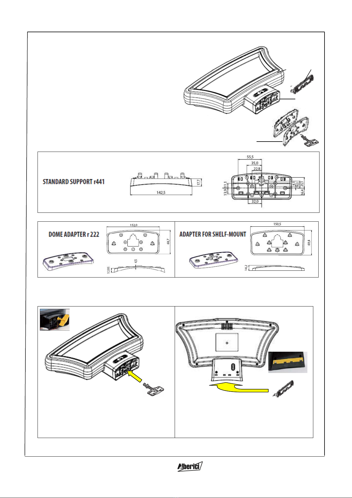
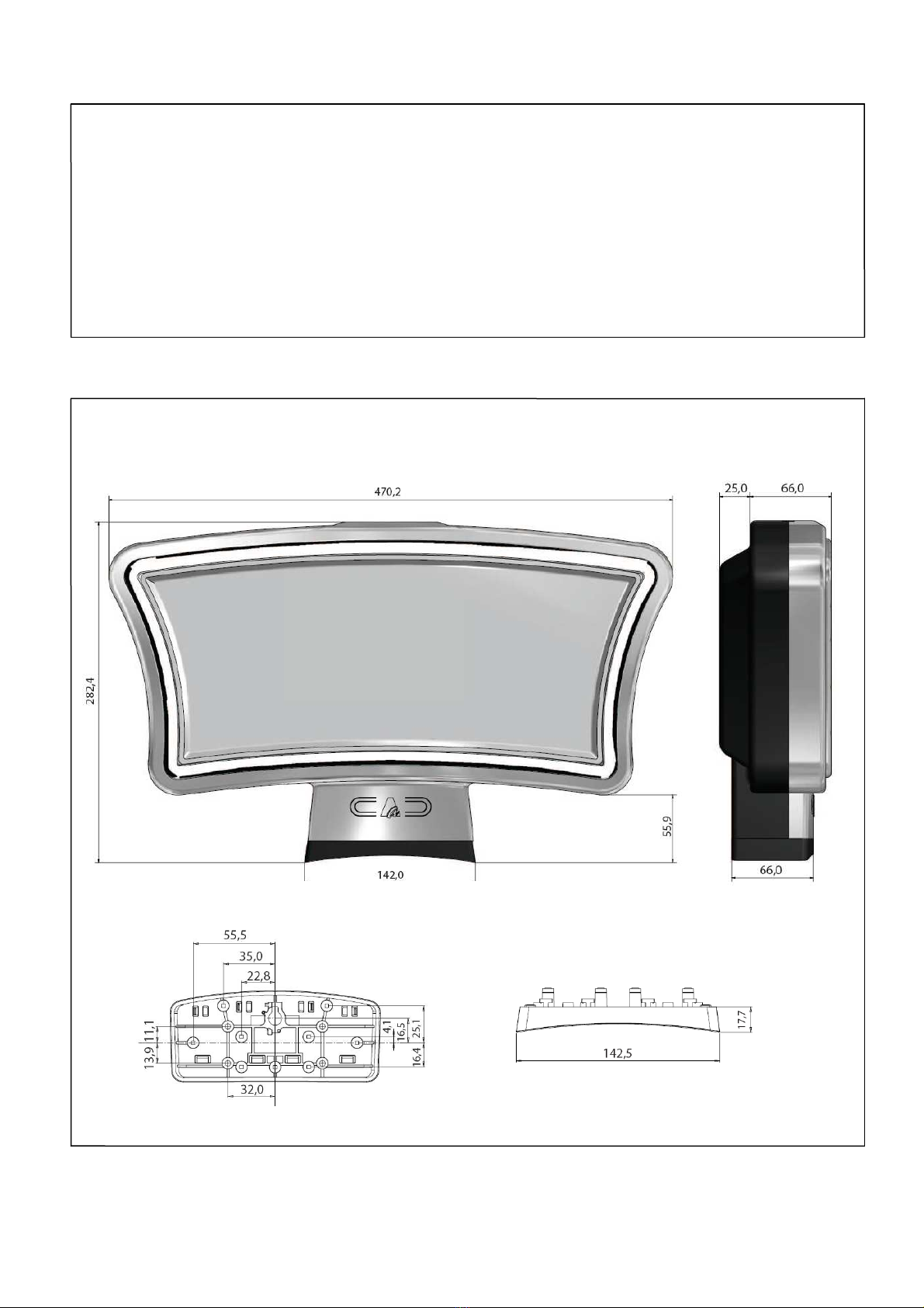
MOUNTING THE TOPPER
1. Fasten the standard support (B) on the machine dome. Add the adapter (C) if the
radius of the dome is 222 mm, or else add the adapter (D) if the Topper is to be
mounted onto a shelf. See dimensional drawings, pag. 3 .
2. Slip the Shuttle harness into the
dome.
Take care that the harness remains
within its seat!
3. Locate the Topper in position.
Pay attention: the support rear hooks
must remain within the Topper base.
ISTRUZIONI
INSTALLAZIONE
VANGUARD
ENG
, 3 di 6

3.
Pull the Topper down
onto the (B) support, then push
it
backward so that the hooks clip in completely in their
seats.
4. Connect the harness to the voltage supplies:
+12 Vcc between yellow (+) and black (GND) wires
+ 5 Vcc between red (+) and black (GND) wires.
5. Two uick-fix modes are available: from the inside of the machine dome, by the
flag-tool E provided (
a
), or, from the Topper rear side, by the fixing bar F (
b
).
a.
Quick-fix by flag-tool:
insert the flag tool E
through the machine dome into its seat in the
Topper support. Rotate it 180° clockwise until it
gets tight. Leave it in its seat.
b.
Quick-fix by fixing bar
: place the fixing bar (F)
in its seat behind the Topper shaft, pull it 5 mm
down, and fasten it by the two screws (G).
provided.
[When choosing method b, take care to
clamp the electric connectors, and to give the
machine cable approx. 10 cm excess lenght: this
will make dismount easy].
6. The traditional method of tightening the Topper and support to the dome can
anyway be used, if preferred.
7. The back-illumination of the artwork can be controlled by the red slide switch in
the rear side of the Shuttle stem.
8. Switch the machine on and check operation of the Topper Light.
DISMOUNTING THE TOPPER
1.
Switch the machine OFF
.
2.
a. If the Topper is mounte by flag-tool:
open the dome and disconnect the harnesses.
Turn flag-tool 180° anticklockwise, and remove the tool.
Pull the Topper forward and lift it up, removing it from its
support.
b. If the Topper is mounte by fixing-bar:
remove the two screws (G), slip the bar 5 mm upwards and
unlock it. Pull the Topper forward and lift it up, removing it
from its support. Gently pull the harness until its connector
plug pops out, then disconnect it from the machine harness.
ISTRUZIONI
INSTALLAZIONE
VANGUARD
ENG
, 4 di 6
On/Off swich for
artwork
illumination
Push this
direction
(B)
Standard
support
Pull this
directti
on
to
dismount
Artwork
backlight by
L D strip
(3p MAT -N-
LOCK PLUG)

MOUNTING/REPLACING THE ARTWORK
Lay the topper face down. Remove the 6 screws placed along the rear perimetre as well
as the 2 screws located in the stem rear face. Rotate the topper face up, lift up the
front bezel and lay it aside.
Pull apart the two plexy layers, put back the lower one on the support ribs, fit the
artwork and cover it by the upper plexy layer.
Fit the front bezel, hold the whole Topper and again lay it face down. Pay attention not
to stretch the power harness. Tighten the 8 screws in.
SIZE

Alberici S.p.A. reserves the right to make modifications on the Products
here described without previous notice, to the aim of constantly improve the Products.
IMPORTANT! Comply with the regulations when recycling
packing waste or when scrapping the pro uct!
Ref.: EU Directive 2002/96/EC
NOTICE
This manual suits for next models
3
Table of contents
Popular Lighting Equipment manuals by other brands

ABB
ABB Thomas&Betts Standard installation manual

VISIO
VISIO BW-54-3RGBW IV user manual

Elation
Elation KL FRENSEL 6 user manual

Starling Technologies
Starling Technologies Pocket Spin Drift instruction manual

HERRMANS
HERRMANS H-TRACE DYNAMO user manual

emaux
emaux FSF350-6W Installation & operating instruction