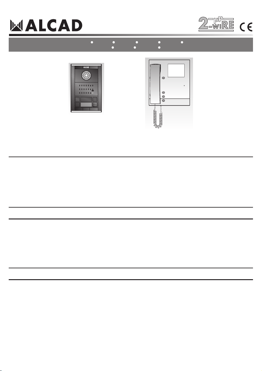
VÍDEOPORTERO 2 HILOS - 2-WIRE VIDEODOOR ENTRY SYSTEMS - VIDÉOPORTIER 2 FILS
AUSENCIA DE LLAMADA. SISTEMA EN REPOSO
NO CALL. SYSTEM ON STAND-BY
ABSENCE D'APPEL. SYSTÈME EN REPOS
3
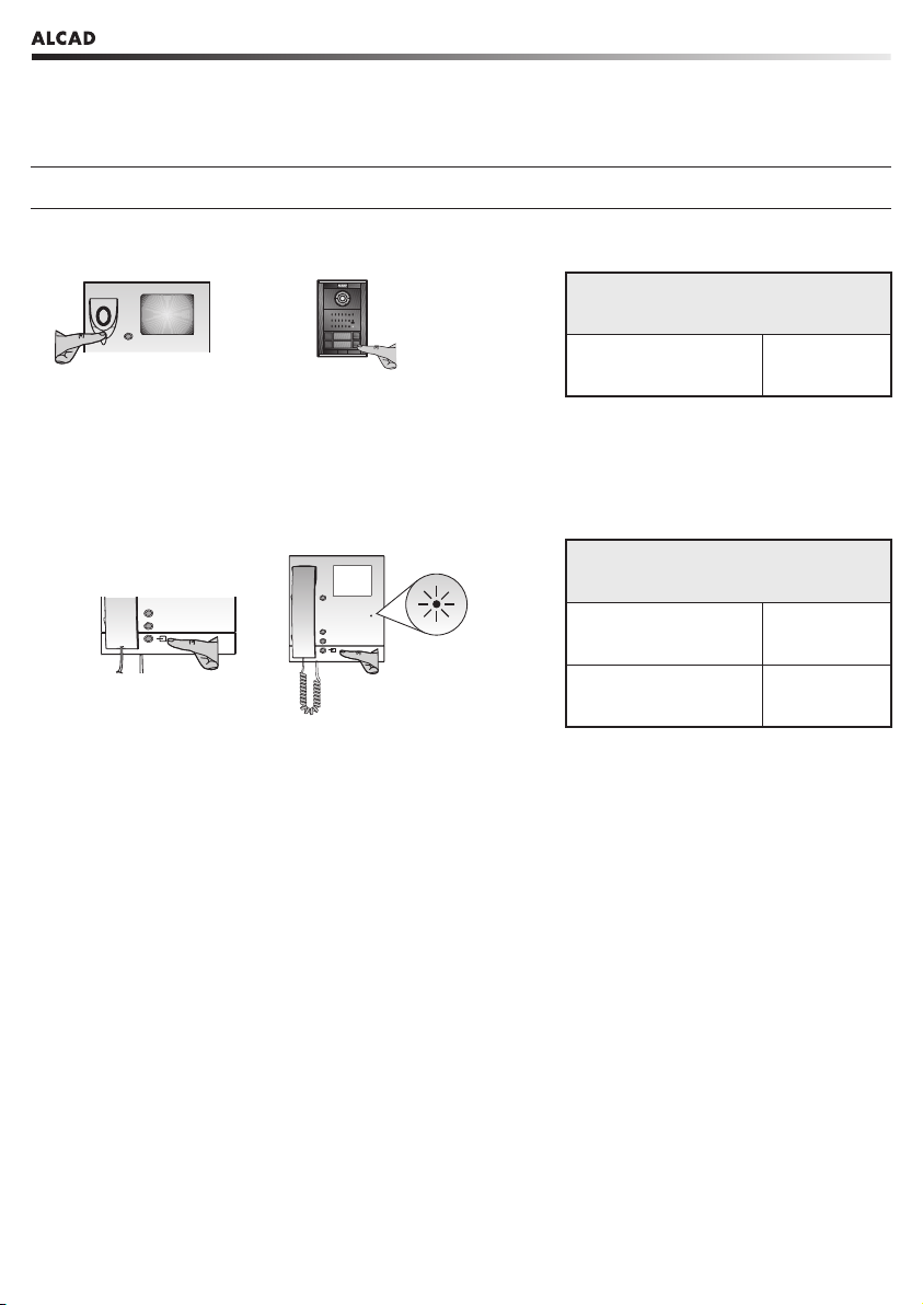
Los monitores se encuentran por defecto inactivos, de manera que las funciones de comunicación con la placa de calle y apertura de
puerta están inhabilitadas. Las placas de calle se encuentran en reposo, con el sistema de audio deshabilitado y a la espera de que
se realice alguna llamada o de que algún monitor active el sistema de autoencendido.
SISTEMA ACTIVO
SYSTEM ACTIVE
SYSTÈME ACTIF
El sistema pasa de estado de reposo a activo cuando el monitor de una vivienda recibe llamada desde una placa de calle o cuando
se activa la función de autoencendido desde uno de los monitores.
By default the monitors are inactive, so that the functions of communicating with the entrance anel and o ening the door are disabled.
The entrance anels are on standby, with the audio system disabled while waiting for a call to be made or for a monitor to activate
the automatic switch-on system.
Par défaut, les moniteurs sont inactifs, de sorte que les fonctions de communication avec la plaque de rue et douverture de porte soient
inhibées. Les plaques de rue sont en veille, avec le système audio inhibé en attendant que quelquun fasse un appel ou quun moniteur
active le système dautoallumage.
Dos estados de funcionamiento: sistema en reposo y sistema activo.
There are two o erating states: system on standby and system active.
Il y a deux états de fonctionnement: système en veille et système actif.
The system changes from being on standby to being in the active state when the monitor in a dwelling receives a call from an entrance
panel or when the automatic switch-on feature is activated from one of the monitors.
Le système passe de létat de veille à létat actif lorsque le moniteur dun logement reçoit un appel depuis une plaque de rue ou lorsque
la fonction dautoallumage est activée depuis un des moniteurs.
REALIZAR UNA LLAMADA A UNA VIVIENDA
MAKING A CALL TO A DWELLING
REALISATION D'UN APPEL A UN LOGEMENT
Para llamar a una vivienda, presione el pulsador correspondiente de la placa de calle. La placa emitirá unos tonos de confirmación
de llamada. Si el auricular del monitor está descolgado, la placa emitirá tonos intermitentes.
To make a call to a dwelling, ress the corres onding ush-button on the entrance anel with ush-buttons. The anel emits a confirmation
tone. If the handset of the monitor called is off the hook, intermittent tones will be heard at the entrance anel.
Pour réaliser un appel à un logement, appuyez sur le bouton-poussoir correspondant de la plaque de boutons-poussoirs de la plaque
de rue. La plaque émettra un signal sonore de validation. Si le moniteur est décroché, la plaque émettra des tonalités intermitentes.
Confirmación de llamada
Confirmation of the call
Confirmation de l'appel
TEMPORIZACIONES
TIME-SETTINGS
TEMPORISATION
30 Segundos
Seconds
Secondes
60 Segundos
Seconds
Secondes
PIP... PIP... PIP
Tiempo para contestar:
Time to answer:
Temps de réponse:
Tiempo de conversación:
Time for conversation:
Temps de conversation:
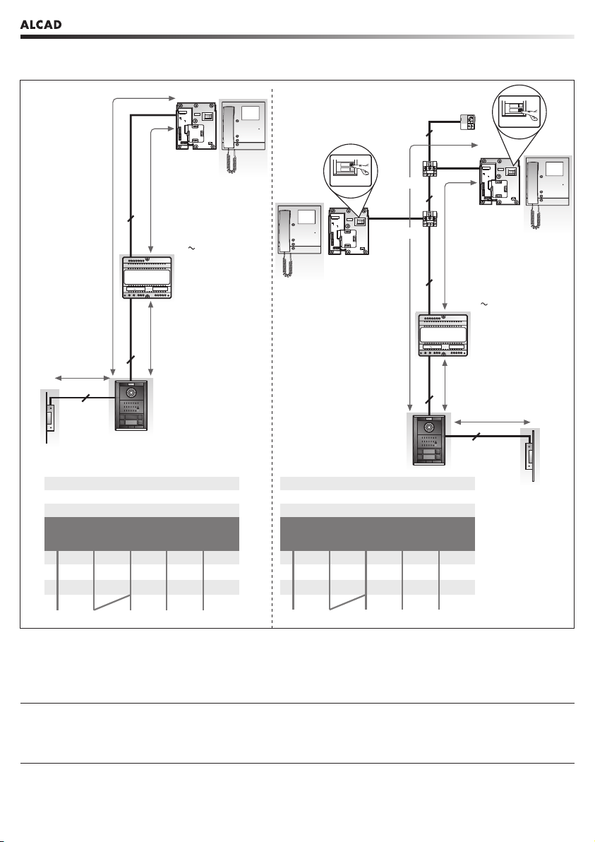
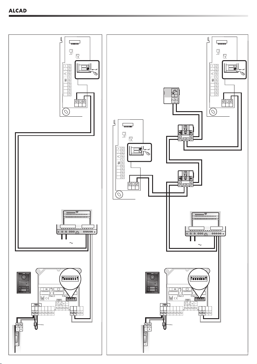
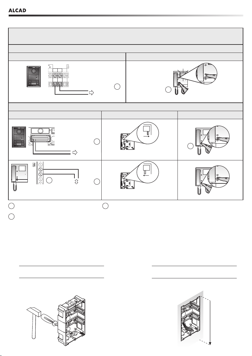
FUNCIONAMIENTO GENERAL DEL SISTEMA DE PORTERO
GENERAL OPERATION OF THE DOOR ENTRY SYSTEM
FONCTIONNEMENT GÉNÉRAL DU SYSTÈME DE PORTIER