manuals.online logo
Brands
  1. Home
  2. •
  3. Brands
  4. •
  5. Alcoa
  6. •
  7. Power Tools
  8. •
  9. Alcoa BTT20SF User manual

Alcoa BTT20SF User manual

Other Alcoa Power Tools manuals

Alcoa 257 User manual

Alcoa

Alcoa 257 User manual

Alcoa ERT7 User manual

Alcoa

Alcoa ERT7 User manual

Alcoa HUCK HK480 User manual

Alcoa

Alcoa HUCK HK480 User manual

Alcoa MP-3V 39045 User manual

Alcoa

Alcoa MP-3V 39045 User manual

Alcoa 243 User manual

Alcoa

Alcoa 243 User manual

Alcoa 244 User manual

Alcoa

Alcoa 244 User manual

Alcoa 2013 User manual

Alcoa

Alcoa 2013 User manual

Alcoa 2025 SERIES User manual

Alcoa

Alcoa 2025 SERIES User manual

Alcoa B4600 User manual

Alcoa

Alcoa B4600 User manual

Alcoa HUCK 588RR User manual

Alcoa

Alcoa HUCK 588RR User manual

Alcoa 244BT User manual

Alcoa

Alcoa 244BT User manual

Alcoa Huck 2600 Series User manual

Alcoa

Alcoa Huck 2600 Series User manual

Popular Power Tools manuals by other brands

ISLAND HOPPER Power Egg HT-309 operating instructions

ISLAND HOPPER

ISLAND HOPPER Power Egg HT-309 operating instructions

Sioux Tools SSR6P25 Instructions-parts list

Sioux Tools

Sioux Tools SSR6P25 Instructions-parts list

Makita HM1317C technical information

Makita

Makita HM1317C technical information

ABB Smart Tool + quick start guide

ABB

ABB Smart Tool + quick start guide

Baumr-AG BMJK-24S user manual

Baumr-AG

Baumr-AG BMJK-24S user manual

Bosch Professional GST 18 V-LI S Original instructions

Bosch

Bosch Professional GST 18 V-LI S Original instructions

Ronix RA-2702 quick start guide

Ronix

Ronix RA-2702 quick start guide

Nordson ProBlue user guide

Nordson

Nordson ProBlue user guide

aoyue int6028 instruction manual

aoyue

aoyue int6028 instruction manual

Hitachi CJ 65VA2 Instruction manual and safety instructions

Hitachi

Hitachi CJ 65VA2 Instruction manual and safety instructions

Makita HM1304 instruction manual

Makita

Makita HM1304 instruction manual

Kurtz Ersa Ersa X-TOOL VARIO operating instructions

Kurtz Ersa

Kurtz Ersa Ersa X-TOOL VARIO operating instructions

SCHUNK KSO 65 Installation and operating instruction

SCHUNK

SCHUNK KSO 65 Installation and operating instruction

Harken LokHead 500 user manual

Harken

Harken LokHead 500 user manual

Senco DuraSpin ExTPro installation instructions

Senco

Senco DuraSpin ExTPro installation instructions

Ferm JSM1020 Original instructions

Ferm

Ferm JSM1020 Original instructions

Milwaukee M12 FUEL 2559-20 Operator's manual

Milwaukee

Milwaukee M12 FUEL 2559-20 Operator's manual

EINHELL BT-CD 12/2 operating instructions

EINHELL

EINHELL BT-CD 12/2 operating instructions

manuals.online logo
manuals.online logoBrands
  • About & Mission
  • Contact us
  • Privacy Policy
  • Terms and Conditions

Copyright 2025 Manuals.Online. All Rights Reserved.

1
BTT20SF Cutter and
Installation tool
Assembly
2
BTT20SF Cutter
and Installation tool
Installation tool
6.5” O.A.L.
Weight 11 lbs.
2” stroke
Cutter tool
8” O.A.L.
Weight 12 lbs.
2” stroke
3
Section 1…………………………………Handle Assembly
Section 2………………………………..Cylinder Assembly
Section 3………………..Limit switch housing Assembly
Section 4…………………………...Cutter Nose Assembly
Section 5……………………..Installation Nose Assembly
Section 6…………………………..Setting the limit switch
Index
BTT20SF Cutter Tool and
Installation tool Assembly
4
Section #1
BTT20SF Handle Assembly
5
Hydraulic Manifold for the
BTT20SF tool.
Now the Hydraulic hoses can
be screwed into the manifold
using a hydraulic loctite thread
sealer and tightened down.
Slide the handle over the
hydraulic quick disconnects and
up the hoses to the manifold.
Then insert the lemo wire
through the strain relief which is
attached to the alum. Base
plate and feed the wires up
through the handle and attach
the alum. Base plate using two
#10-24x1/2” long BHCS.
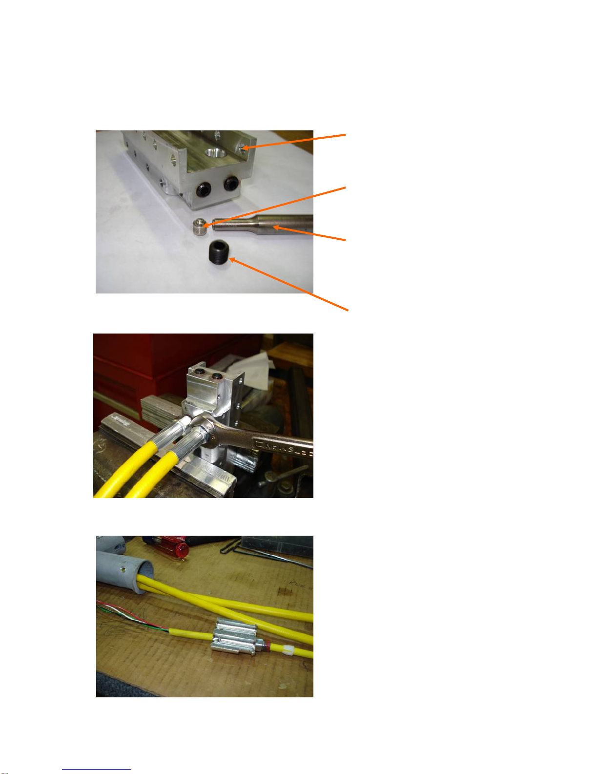
CV plugs (CVES2503231A Dia.
.250” short) are put into the
manifold first using a hammer
and the installation tool
Then a 1/16x5/16 socket
pressure plug (3/4 taper) with
blue loctite is screwed into the
manifold.
Installation tool
(CVTS060) required by the CV
manufacture.
Handle Assembly (cont’d)
6
The wires, RED and GREEN go
through the handle and manifold for
the micro switch.
Place the handle up onto the
manifold and put the #10-32x3/8”
BHCS into the handle which will
attach the manifold to the handle.
Slide the other half of the alum.
Base plate onto the hydraulic hose
and push into place for the other
two #10-24X3/3” BHCS.
Then the BLACK and WHITE wires
go out through the trigger housing
until the trigger is connected. At this
point you can push the trigger into the
trigger housing hole in the handle.
Handle Assembly (cont’d)
7
With the handle attached to the
manifold put a small amount of
lubriplate grease around the holes
in the top of the manifold where
the barrel connectors go.
Then put some lubriplate grease
on the assembled barrel
connectors ( o-rings and back-
up rings) and push carefully into
the holes in the manifold.
Install the second barrel
connector using the same
process as the first.
Handle Assembly (cont’d)
8
When sliding the hydraulic cylinder
onto the barrel connectors, be careful
when not to pinch or tear the o-rings or
back up rings.
Attach the hydraulic cylinder to the
handle using a # 10-32x3/8” BHCS.
Put the limit switch rod into the tool
before the puller gets screwed into
the end cap.
Handle Assembly (cont’d)
9
Section #2
BTT20SF Hydraulic
Cylinder Assembly
#14
#13
#12
#11
#10
#9
#8
#7
#6
Part No. Industry Standard
Generic Part number
MaterialDescription
Standard Replacement Part Numbers
227Urethaneback-up ring
227Urethaneo-ring
220Urethaneo-ring
220Urethaneback-up ring
227Urethaneo-ring
227Urethaneback-up ring
224Urethaneback-up ring
224Urethaneo-ring
AN19Urethanerod wiper
10
AN-19 Rod wiper
224 O-ring
224 Back up ring
Cylinder
End Cap
227 O-ring
227 back up ring
Cylinder Assembly (cont’d)