ERT7 and ERT8 Series Tooling Alcoa Fastening Systems
10
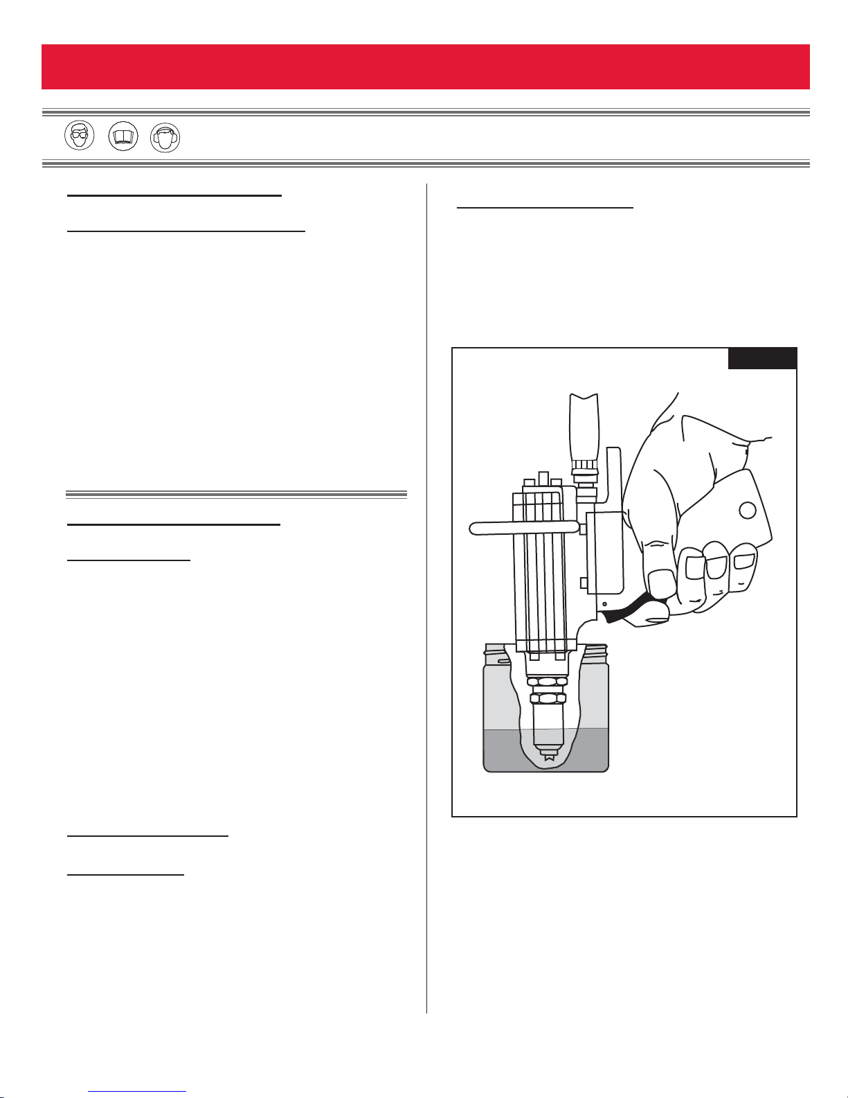
DISASSEMBLY
This manual provides operating and service procedures
for the Rivet Tool models ERT7 and ERT8. Close atten-
tion must be directed to the recommended service pro-
cedures contained in this manual. Specific instructions
for each tool are given under that tool model number
heading. While the tools look similar, each tool contains
parts not used on the other models and removal and
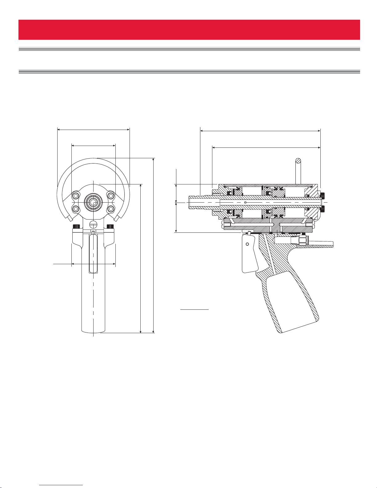
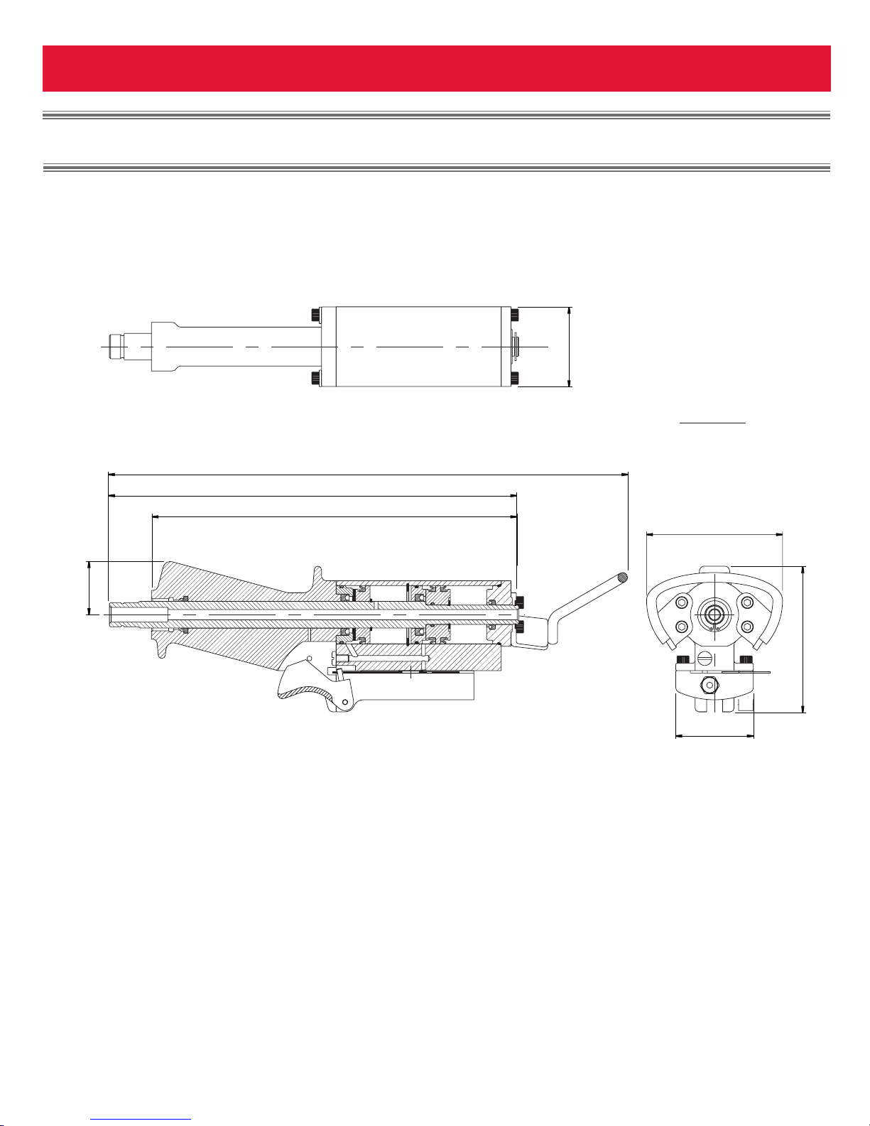
replacement methods will vary. For component identi-
fication and Parts Lists refer to Figures 2 & 3.
NOTE:The following procedure is for complete disas-
sembly of tool. Disassemble only components neces-
sary to replace damaged O-rings, Seals, Back-up Rings,
and worn or damaged components. Always use soft jaw
vice to avoid damage to tool.
Removing the Hose Assembly
Model ERT7: (Figure 2)
Remove Guard (16).
Models ERT7 & ERT8: (Figures 2 & 3)
Remove pintail tube from pulling head assembly.
Remove Cable Attachment from Cylinder Base. Pull
heavy plastic Sleeve off air line Connector (15). Depress
red Collet on air line connector and pull air line out of
connector.
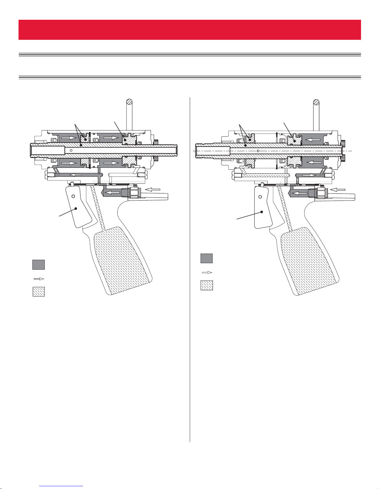
Rivet Tool Disassembly (Figures 2 & 3)
1. With Pulling Head off, remove all nicks and burrs
from front of Piston Rod Assembly (5).
2. Model ERT7: (Figure 2)
Remove four Screws (24) and Piston Rod Guide (1)
from front of tool.
Model ERT8: (Figure 3)
Remove four Screws (24) and Handle (19) from
front of tool.
3. Push Piston Assembly (5) to full back position, and
remove Retaining Ring (12) from rear of Piston
Assembly. Remove all nicks and burrs from rear
of Piston to ensure removal of End Cap and
Double Piston without damage to them.
4. Remove four Screws (24), Support Loop Assembly
(25), and End Cap (14) from rear of tool.
5. Remove Retaining Ring (12) from rear of Double
Piston. Pull Piston Assembly (5) out through the
front end of the tool.
6. Push out Double Piston (11) and Bulkhead (7)
through rear of tool. It is not necessary to remove
Retaining Ring (6) from Cylinder.
ASSEMBLY
For component identification and Parts Lists, refer
to Figures 2 & 3.
NOTE: Clean components with mineral spirits, or similar
solvent. Inspect for wear/damage and replace as neces-
sary. Replace all seals of disassembled components.
Use O-rings, Quad-Rings and Back-up Rings in Service
Parts Kit ERT7KIT or ERT8KIT. Smear O-ring lubricant
on O-rings, Seals, Back-up Rings and mating parts to
ease assembly. Assemble tool taking care not to damage
O-rings, Seals, or Back-up Rings.
NOTE: When installing Retaining Rings, they must
be installed with sharp edge of Retaining Ring
toward rear of tool.
NOTE: When replacing Seals, make sure they are
correctly positioned as shown on the tool drawing.
1. Wipe all seals with a thin film of lubricant prior to
reassembly.
2. Inspect Cylinder (2) wall to ensure the surface is
free of any gouges or nicks that will damage a new
seal. Small gouges or nicks can normally be
removed by using a fine crocus cloth.
3. Install Bulkhead (7) into the rear of the Cylinder (2)
until it seats flat against the Retaining Ring (6) in the
center of the Cylinder.
4. Upon ensuring there are no nicks or burrs on the
front or rear of the Piston Assembly (5), insert the
assembly into the front of the tool, and push it to the
full back position.
5. Install the Double Piston (11) onto the rear of the
Piston Rod Assembly and into the Cylinder until it
bottoms on the shoulder of the Piston Assembly.
S
SER
ERVICING
VICING THE
THE T
TOOL
OOL (cont.)