Alcor AU9525 Product manual

AU9525
USB Smart Card Reader Controller
Technical Reference Manual
www.DataSheet4U.com

AU9525
USB Smart Card Reader Controller
www.DataSheet4U.com

C
Co
op
py
yr
ri
ig
gh
ht
t
Copyright © 1997 - 2007. Alcor Micro, Corp. All Rights Reserved. No part of this data
sheet may be reproduced, transmitted, transcribed, stored in a retrieval system or
translated into any language or computer language, in any form or by any means,
electronic, mechanical, magnetic, optical, chemical, manual or otherwise, without prior
written permission from Alcor Micro, Corp.
T
Tr
ra
ad
de
em
ma
ar
rk
k
A
Ac
ck
kn
no
ow
wl
le
ed
dg
ge
em
me
en
nt
ts
s
The company and product names mentioned in this document may be the trademarks
or registered trademarks of their manufacturers.
D
Di
is
sc
cl
la
ai
im
me
er
r
Alcor Micro, Corp. reserves the right to change this product without prior notice. Alcor
Micro, Corp. makes no warranty for the use of its products and bears no responsibility
for any error that appear in this document. Specifications are subject to change
without prior notice.
R
Re
ev
vi
is
si
io
on
n
H
Hi
is
st
to
or
ry
y
Date Revision Description
Jan 2008 1.00W Official Release
C
Co
on
nt
ta
ac
ct
t
I
In
nf
fo
or
rm
ma
at
ti
io
on
n:
:
Web site: http://www.alcormicro.com/
Taiwan China ShenZhenOffice
Alcor Micro, Corp. Rm.2407-08, Industrial Bank Building
4F, No 200 Kang Chien Rd., Nei Hu, No.4013, Shennan Road,
Taipei, Taiwan, R.O.C. ShenZhen,China. 518026
Phone: 886-2-8751-1984 Phone: (0755) 8366-9039
Fax: 886-2-2659-7723 Fax: (0755) 8366-9101
Santa Clara Office Los Angeles Office
2901 Tasman Drive, Suite 206 9070 Rancho Park Court
Santa Clara, CA 95054 Rancho Cucamonga, CA 91730
USA USA
Phone: (408) 845-9300 Phone: (909) 483-8821
Fax: (408) 845-9086 Fax: (909) 944-0464
www.DataSheet4U.com

<Memo>
www.DataSheet4U.com

i
Table of Contents
1. Introduction ............................................................ 1
1.1 Description...................................................................................1
1.2 Features........................................................................................1
2. Application Block Diagram ...................................2
3. Pin Assignment...................................................... 3
4. System Architecture and Reference Design ....... 6
4.1 AU9525 Block Diagram ...............................................................6
5. Electrical Characteristics...................................... 7
5.1 Recommended Operating Conditions .......................................7
5.2 General DC Characteristics........................................................7
5.3 DC Electrical Characteristics of 3.3V I/O Cells..........................7
6. Mechanical Information......................................... 8
7. Abbreviations ......................................................... 9
www.DataSheet4U.com

ii
List of Figures
Figure 2.1 Block Diagram..................................................................2
Figure 3.1 AU9525 Pin Assignment Diagram..................................3
Figure 4.1 AU9525 Block Diagram ...................................................6
Figure 6.1 Mechanical Information Diagram ...................................8
List of Tables
Table 3.1 AU9525 Pin Descriptions..................................................4
Table 5.1 Recommended Operating Conditions.............................7
Table 5.2 General DC Characteristics..............................................7
Table 5.3 DC Electrical Characteristics of 3.3V I/O Cells ...............7
www.DataSheet4U.com

AU9525 USB Smart Card Reader Controller V1.00W 1
1. Introduction
1
1.
.1
1
D
De
es
sc
cr
ri
ip
pt
ti
io
on
n
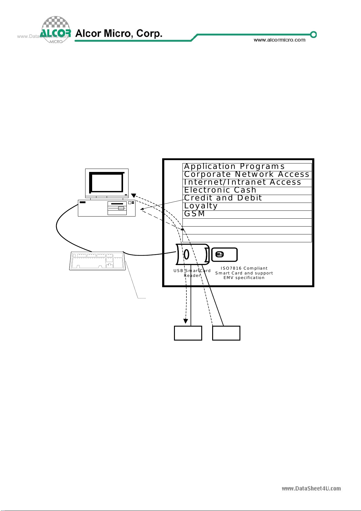
AU9525 is a highly integrated single chip, is the second generation USB Smart Card
reader controller. Highly integration enables the lowest BOM cost of USB Smart Card
reader. The AU9525 supports multiple international standards including ISO7816 for
IC card standard, PC/SC 1.0 for windows smart card standard, Microsoft WHQL, EMV
for Europay MasterCard Visa standard and USB-IF CCID standard. And support
flexible Keyboard/LCM display interface. With our embedded enhanced 8051 MCU,
user can self control Keyboard/LCM display by AP. Manufacturers can easily create a
higher-security Smart Card reader by deploying Au9525. The application of AU9525
can be generally applied to Smart Card read/write terminal device, such as ATM, POS
terminal, Public telephone, E-Commerce, personal consumption on Internet, personal
certification, prepay system, loyalty system…etc.
1
1.
.2
2
F
Fe
ea
at
tu
ur
re
es
s
Support EMV specification
Support the Universal Serial Bus Specification, 2.0 full speed.
Based on ISO7816 implementation
Embedded enhanced 8051 MCU
Support Firmware upgrade mechanism(ISP, In-System Programming)
Support PC Smart Card industry standard – PC/SC 1.0
Support CT-API
Support Microsoft Smart Card for Windows
Meet Microsoft WHQL USB Smart Card Reader requirements
Include WDM driver to work on Windows 98 and Windows 2000
Support dual slots for higher security application
Support Protocol and parameter selection
Support card clock up to 4 MHz
Support T0, T1 protocol, I2C memory card, SLE4418, SLE4428, SLE4432,
SLE4442, AT88SC1608 and AT45D041 card
Dedicated hardware block implementation for IC and memory card protocols
for highest performance
Implemented as an USB full speed device with bulk transfer endpoint
Built-in 3.3V regulator for single 5V operation
Built-in PLL for USB and Smart Card clocks requirement
Support EEPROM for USB descriptors customization, including VID/PID
Available in 64-LQFP Package
Based on USB-CCID class, short and extended APDU level
Compatible with Microsoft USB-CCID driver
Support 3V/5V card
Support 5*6 keypad scan, keypad value can be sent to AP directly
Support different LCM Interface(such as HD44780,KS0108,ST7920 or
compatible)
LCM is controlled by AP, User can develop their AP to support the LCM type
needed
www.DataSheet4U.com

2. Application Block Diagram
AU9525 is a highly integrated single chip, which is used as USB Smart Card reader or
in an embedded USB device in the downstream port of an USB hub. Following is the
application diagram of a typical card reader product withAU9525. By connecting the
card reader to a ATM or E-Commerce…etc.
Figure 2.1 Block Diagram
PC with USB Host Controller
USB Keyboard Hub
USB
Downs
tream
Port
Application Programs
Corporate Network Access
Internet/Intranet Access
Electronic Cash
Credit and Debit
Loyalty
GSM
USB SmartCard
Reader
ISO7816 Compliant
Smart Card and support
EMV specification
Smart Card
Solutions
LCM KBD
AU9525 USB Smart Card Reader Controller V1.00W
2
www.DataSheet4U.com

3. Pin Assignment
The AU9525 is delivered in 64pin LQFP form factor. Documented below is a figure
shows signal names of each pin and a table in the following page describes each pin
in more details.
Figure 3.1 AU9525 Pin Assignment Diagram
Alcor Micro
AU9525
64-PIN LQFP
49505152535455565758596061626364
33
34
35
36
37
38
39
40
41
42
43
44
45
46
47
48
17 18 19 20 21 22 23 24 25 26 27 28 29 30 31 32
1
2
3
4
5
6
7
8
9
10
11
12
13
14
15
16
AVCC
AVSS
XTAL1
XTAL2
PSWOUTB
PSWOUTA
VCC5V
BVCC
USB_DP
USB_DM
BVSS
ChipRstN
LCD_EN
GPI_0
LCD_RW
GPI_1
LCD_RS
SCL
SDA
LCD_BL
LCD_CS1
Key_Row4
Key_Row3
Key_Row2
Key_Row1
Key_Row0
Port1_2
Port1_3
Port1_4
Port1_5
Port1_6
Port1_7
Key_Co15
Key_Co14
Key_Co13
Key_Co12
Key_Co11
Key_Co10
LCD_Dat0
LCD_Dat1
VCC
VSS
LCD_Dat2
LCD_Dat3
LCD_Dat4
LCD_Dat5
LCD_Dat6
LCD_Dat7
RXD
ICC1DETECTN
SCAD1DATA
SCARD1Rst
SCARD1FCB
SCARD1C6
SCARD1C8
ICC0DECTEN
SCARD0DATA
SCARD0CLK
SCARD0RST
SCARD0FCB
SCARD0C6
SCARD0C8
AU9525 USB Smart Card Reader Controller V1.00W 3
www.DataSheet4U.com

Table 3.1 AU9525 Pin Descriptions
Pin # Pin Name I/O Description
1 AVCC PWR Analog 3.3V power supply
2 AVSS PWR Analog ground.
3 XTAL1 I Crystal Oscillator Input (12MHz).
4 XTAL2 O Crystal Oscillator Output (12MHz).
5 PSWOUTB O Connect to Slot1 Power.
6 PSWOUTA O Connect to Slot0 Power.
7 VCC5V PWR 5V power supply Input
8 BVCC PWR 3.3V power supply output
9 USB_DP I/O USB D+
10 USB_DM I/O USB D-
11 BVSS PWR Chip I/O Ground.
12 ChipRstN I Chip Reset
13 LCD_En O LCD Enable(High effective).
14 GPI_0 I Reserved (need pull down)
15 LCD_Rw O LCD Read/Write.0:write;1:read.
16 GPI_1 I Reserved (need pull down)
17 LCD_RS O LCD driver dedicated I/O line: LCD Register Select.
18 SCL I/O EEPROM Clock (need pull high)
19 SDA I/O EEPROM Data (need pull high)
20 LCD_BL O LCD Background Light control,1:on,0:off.
21 LCD_CS1 O LCD Display control(To select the left side or right
side).
22 Key_Row4 I Keyboard row input 4.
23 Key_Row3 I Keyboard row input 3.
24 Key_Row2 I Keyboard row input 2.
25 Key_Row1 I Keyboard row input 1.
26 Key_Row0 I Keyboard row input 0.
27 PORT1_2 O Slot1 LED
28 PORT1_3 O Slot2 LED
29 PORT1_4 O Card Power LED
30 PORT1_5 I PID/VID ("1": 9525 one slot mode, "0": 9526 two slot
mode, default: "1")
31 PORT1_6 I Reserved(need pull Low)
32 PORT1_7 I Reserved(need pull Low)
33 Key_Col5 I Keyboard columniation input 5.
AU9525 USB Smart Card Reader Controller V1.00W
4
www.DataSheet4U.com

Pin # Pin Name I/O Description
34 Key_Col4 I Keyboard columniation input 4.
35 Key_Col3 I Keyboard columniation input 3.
36 Key_Col2 I Keyboard columniation input 2.
37 Key_Col1 I Keyboard columniation input 1.
38 Key_Col0 I Keyboard columniation input 0.
39 LCD_Dat0 I/O LCD driver dedicated I/O lines-data0.
40 LCD_Dat1 I/O LCD driver dedicated I/O lines-data1.
41 VCC PWR Core power supply 3.3V
42 VSS PWR Core ground
43 LCD_Dat2 I/O LCD driver dedicated I/O lines - Data pin2.
44 LCD_Dat3 I/O LCD driver dedicated I/O lines - Data pin3.
45 LCD_Dat4 I/O LCD driver dedicated I/O lines - Data pin4.
46 LCD_Dat5 I/O LCD driver dedicated I/O lines - Data pin5.
47 LCD_Dat6 I/O LCD driver dedicated I/O lines - Data pin6.
48 LCD_Dat7 I/O LCD driver dedicated I/O lines - Data pin7.
49 TXD O RS232 output pin
50 RXD I RS232 input pin
51 ICC1DETECTN I Smart card 1 inserted (Low true) (pull high)
52 SCARD1DATA I/O Smart card 1 serial data
53 SCARD1CLK I/O Smart card 1 clock
54 SCARD1RST I/O Smart card 1 reset
55 SCARD1FCB I/O Smart card 1 GPIO_0
56 SCARD1C6 I/O Smart card 1 GPIO_1
57 SCARD1C8 I/O Smart card 1 GPIO_2
58 ICC0DECTEN I Smart card 0 inserted (Low true)(pull high)
59 SCARD0DATA I/O Smart card 0 serial data
60 SCARD0CLK I/O Smart card 0 clock
61 SCARD0RST I/O Smart card 0 reset
62 SCARD0FCB I/O Smart card 0 GPIO_0
63 SCARD0C6 I/O Smart card 0 GPIO_1
64 SCARD0C8 I/O Smart card 0 GPIO_2
AU9525 USB Smart Card Reader Controller V1.00W 5
www.DataSheet4U.com

4. System Architecture and Reference
Design
4
4.
.1
1
A
AU
U9
95
52
25
5
B
Bl
lo
oc
ck
k
D
Di
ia
ag
gr
ra
am
m
Figure 4.1 AU9525 Block Diagram
XCVR
Processor
EEPROM
Interface
ROM Smart
Card FIFO
Reset
3.3V
Voltage
Regulator
USB
Upstream
Port
Card Eject
Card Reset
Card Insert
Optional
256 Bytes
EEPROM
Card Data
Card Clock
Smart
Card
Control
RAM
USB
FIFO
USB
SIE
12MHz
XTAL
3.3
Card
Power
AU9525 USB Smart Card Reader Controller V1.00W
6
www.DataSheet4U.com

5. Electrical Characteristics
5.1 Recommended Operating Conditions
Table 5.1 Recommended Operating Conditions
SYMBOL PARAMETER MIN TYP MAX UNITS
V5IN Power Supply 4.75 5.0 5.25 V
VDDHM Power Supply 3.0 3.3 3.6 V
TOPR Operating Temperature 0 85 OC
TSTG Storage Temperature -40 125 OC
5
5.
.2
2
G
Ge
en
ne
er
ra
al
l
D
DC
C
C
Ch
ha
ar
ra
ac
ct
te
er
ri
is
st
ti
ic
cs
s
Table 5.2 General DC Characteristics
SYMBOL PARAMETER CONDITIONS MIN TYP MAX UNITS
IIN Input low current no pull-up or
p
ull-down -1 1 µA
IIH Input high current no pull-up or
p
ull-down -1 1 µA
IOZ Tri-state leakage current -10 10 µA
CIN Input capacitance Pad Limit 5 ρF
COUT Output capacitance Pad Limit 5 ρF
CBID Bi-directional buffer
ca
p
acitance Pad Limit 5 ρF
5
5.
.3
3
D
DC
C
E
El
le
ec
ct
tr
ri
ic
ca
al
l
C
Ch
ha
ar
ra
ac
ct
te
er
ri
is
st
ti
ic
cs
s
o
of
f
3
3.
.3
3V
V
I
I/
/O
O
C
Ce
el
ll
ls
s
Table 5.3 DC Electrical Characteristics of 3.3V I/O Cells
Limits
SYMBOL PARAMETER CONDITIONS MIN TYP MAX UNIT
VIL Input low voltage CMOS 0.9 V
VIH Input high voltage CMOS 2.3 V
VOL Output low voltage ∣IOL∣=2~16mA 0.4 V
VOH Output high voltage ∣IOH∣=2~16mA 2.4 V
RIInput Pull-up/down
resistance VIL=0V or
VIH=VCC 10K/20
0K KΩ
AU9525 USB Smart Card Reader Controller V1.00W 7
www.DataSheet4U.com

6. Mechanical Information
Figure 6.1 Mechanical Information Diagram
E1
E
DD1
be
C1 A2 A
L1
L
0.25
GAUGE PLANE
SEATING PLANE A1
SYMBOLS MIN. MAX.
A -- 1.60
A1 0.05 0.15
A2 1.35 1.45
b 0.17 0.27
c1 0.09 0.16
D 12.00 BSC
D1 10.00 BSC
E 12.00 BSC
E1 10.00 BSC
e 0.50 BSC
L 0.45 0.75
L1 1.00 REF
1. JEDEC OUTLINE: MS-026 BCD
2. DIMENSIONS D1 AND E1 DO NOT
INCLUDE MOLD PROTRUSION.
ALLOWABLE PROTRUSION IS 0.25mm
PER SIDE. D1 AND E1 ARE MAXIMUM
PLASTIC BODY SIZE DIMENSIONS
INCLUDING MOLD MISMATCH.
3. DIMENSION b DOES NOT INCLUDE
DAMBAR PROTRUSION. ALLOWABLE
DAMBAR PROTRUSION SHEALL NOT
CAUSE THE LEAD WIDTH TO EXCEED
THE MAXIMUM b DIMENSION BY MORE
THAN 0.08mm.
AU9525 USB Smart Card Reader Controller V1.00W
8
www.DataSheet4U.com

7. Abbreviations
In this chapter some of the terms and abbreviations used throughout the technical
reference manual are listed as follows.
WHQL Windows Hardware Quality Labs
EMV Europay MasterCard Visa
ATM Automatic Teller Machine
BOM Bill of Material
PC/SC This is association name. (http://www.pcscworkgroup.com/)
VID Vendor ID
PID Product ID
PLL Phase Lock Loop
GSM Globe System for Mobile Communication
ESD Electrostatic Sensitive Device
About Alcor Micro, Corp.
Alcor Micro, Corp. designs, develops and markets highly integrated and advanced
peripheral semiconductor, and software driver solutions for the personal computer
and consumer electronics markets worldwide. We specialize in USB solutions and
focus on emerging technology such as USB and IEEE 1394. The company offers a
range of semiconductors including controllers for USB hub, integrated keyboard/USB
hub and USB Flash memory card reader…etc. Alcor Micro, Corp. is based in Taipei,
Taiwan, with sales offices in Taipei, Japan, Korea and California. Alcor Micro is
distinguished by its ability to provide innovative solutions for spec-driven products.
Innovations like single chip solutions for traditional multiple chip products and
on-board voltage regulators enable the company to provide cost-efficiency solutions
for the computer peripheral device OEM customers worldwide.
AU9525 USB Smart Card Reader Controller V1.00W 9
www.DataSheet4U.com
Table of contents
Other Alcor Controllers manuals
Popular Controllers manuals by other brands

AMX
AMX NetLinx Integrated Controller NI-900 installation guide

innovair
innovair SLIM24 Installation and owner's manual

Boston gear
Boston gear Ratiotrol P-3026-BG Installation and operation

Graco
Graco Trabon LC-1000 user manual

Nexmosphere
Nexmosphere XPERIENCE XN-125 quick start guide

RBH Sound
RBH Sound UNC100 manual