Admag SE100DJ/EJ User manual

User's
Manual
Yokogawa Electric Corporation
Models SE100DJ/EJ, SE200DJ/EJ
and SE300DJ/EJ
Magnetic Flow Tube
IM 1E10D0-01E
IM 1E10D0-01E
8th Edition

i
CONTENTS
IM 1E10D0-01E
8th Edition: Apr. 2002(YK)
All Rights Reserved, Copyright © 1998, Yokogawa Electric Corporationrd
Contents
1. INTRODUCTION .............................................................................................. 1-1
2. HANDLING PRECAUTIONS .......................................................................... 2-1
2.1 Checking Model and Specifications ............................................................... 2-1
2.2 Accessories ...................................................................................................... 2-1
2.3 Storage Precautions ......................................................................................... 2-1
2.4 Installation Location Precautions.................................................................... 2-1
2.5 Terminal Box Reorientation Precautions........................................................ 2-1
3. INSTALLATION................................................................................................ 3-1
3.1 Piping Design Precautions .............................................................................. 3-1
3.2 Handling Precautions ...................................................................................... 3-3
3.2.1 General Precautions ................................................................................. 3-3
3.2.2 Flow Tube Piping ..................................................................................... 3-4
3.3 Mounting ......................................................................................................... 3-4
3.3.1 Nominal Diameter 15mm (0.5˝) to 40mm (1.5˝) Wafer Type ................. 3-4
3.3.2 Nominal Diameter 50 mm(2˝) to 200 mm(8˝) Wafer Type ..................... 3-6
3.3.3 Nominal Diameter 15 mm (0.5˝) to 400 mm (16˝) Flange Type ............. 3-8
3.4 Wiring Precautions........................................................................................ 3-10
3.4.1 Grounding .............................................................................................. 3-10
3.4.2 General Precautions ............................................................................... 3-10
3.4.3 Cable Types............................................................................................ 3-10
3.4.4 Connnection to SE14 Magnetic Flow Converter ................................... 3-11
3.4.5 Wiring Ports ........................................................................................... 3-11
4. MAINTENANCE................................................................................................ 4-1
4.1 Regular Inspection Items ................................................................................ 4-1
4.2 Trouble Shooting............................................................................................. 4-1
5. OUTLINE............................................................................................................ 5-1
6. EXPLOSION PROTECTED TYPE INSTRUMENT .................................... 6-1
6.1 CENELEC ATEX(KEMA)............................................................................. 6-1
6.2 FM ................................................................................................................... 6-2
6.3 CSA ................................................................................................................. 6-2
6.4 SAA ................................................................................................................. 6-3
7. PRESSURE EQUIPMENT DIRECTIVE........................................................ 7-1
IM 1E10D0-01E
1-1
1. INTRODUCTION
1. INTRODUCTION
This instrument has been already adjusted at the
factory before shipment.
To ensure correct use of the instrument, please read
this manual thoroughly and fully understand how to
operate the instrument before operating it.
Regarding This Manual
•This manual should be passed on to the end user.
•Before use, read this manual thoroughly to compre-
hend its contents.
•The contents of this manual may be changed
without prior notice.
•All rights reserved. No part of this manual may be
reproduced in any form without Yokogawa’s written
permission.
•Yokogawa makes no warranty of any kind with
regard to this material, including, but not limited to,
implied warranties of merchantability and suitability
for a particular purpose.
•All reasonable effort has been made to ensure the
accuracy of the contents of this manual. However, if
any errors are found, please inform Yokogawa.
•Yokogawa assumes no responsibilities for this
product except as stated in the warranty.
•If the customer or any third party is harmed by the
use of this product, Yokogawa assumes no responsi-
bility for any such harm owing to any defects in the
product which were not predictable, or for any
indirect damages.
Safety Precautions
•The following general safety precautions must be
observed during all phases of operation, service, and
repair of this instrument. Failure to comply with
these precautions or with specific WARNINGS
given elsewhere in this manual violates safety
standards of design, manufacture, and intended use
of the instrument. YOKOGAWA Electric Corpora-
tion assumes no liability for the customer’s failure to
comply with these requirements. If this instrument is
used in a manner not specified in this manual, the
protection provided by this instrument may be
impaired.
The following safety symbol marks are used in
this manual and instrument;
WARNING
A WARNING sign denotes a hazard. It calls
attention to procedure, practice, condition or the
like, which, if not correctly performed or adhered
to, could result in injury or death of personnel.
CAUTION
A CAUTION sign denotes a hazard. It calls
attention to procedure, practice, condition or the
like, which, if not correctly performed or adhered
to, could result in damage to or destruction of
part or all of the product.
IMPORTANT
A IMPORTANT sign denotes an attention to
avoid leading to damage to instrument or system
failure.
NOTE
A NOTE sign denotes a information for essential
understanding of the operation and features.
Protective grounding terminal.
Function grounding terminal. This terminal
should not be used as a “Protective grounding
terminal”.
Alternating current.
Direct current.

IM 1E10D0-01E
1-2
1. INTRODUCTION
Warranty
•The guaranteed term of this instrument is described
in the quotation. We repair the damages that
occurred during the guaranteed term for free.
•Please contact with our sales office when this
instrument is damaged.
•If the instrument has trouble, please inform us
model code, serial number, and concrete substances
or situations. It is preferable to be attached a outline
or data.
•We decide after the examination if free repair is
available or not.
•Please consent to the followings for causes of
damages that are not available as free repair, even if
it occured during the guaranteed term.
A:Unsuitable or insufficient maintenance by the
customer.
B: The handling, using, or storage that ignore the
design and specifications of the instrument.
C: Unsuitable location that ignore the description in
this manual.
D:Remaking or repair by a person except whom we
entrust.
E: Unsuitable removing after delivered.
F: A natural disaster (ex. a fire, earthquake, storm and
flood, thunderbolt) and external causes.
For Safety Using
For safety using the instrument, please give attention
mentioned below.
WARNING
(1) Installation
•The instrument must be installed by expert
engineer or skilled personnel. The procedures
described about INSTALLATION are not
permitted for operators.
•The Magnetic Flow Tube is a heavy instrument.
Please give attention to prevent that persons
are injured by carrying or installing. It is prefer-
able for carrying the instrument to use a cart
and be done by two or more persons.
•In case of high process temperature, care
should be taken not to burn yourself because
the surface of body and case reach a high
temperature.
•When removing the instrument from hazardous
processes, avoid contact with the fluid and the
interior of the flow tube.
•All installation shall comply with local install-
ation requirement and local electrical code.
(2) Wiring
•The instrument must be installed by expert
engineer or skilled personnel. The procedures
described about WIRING are not permitted for
operators.
•Please confirm voltages between the power
supply and the instrument before connecting
the power cables. And also, please confirm
that the cables are not powered before con-
necting.
•The protective grounding must be connected to
the terminal in order to avoid personal shock
hazard.
(3) Operation
•Wait 10 min. after power is turned off, before
opening the covers.
(4) Maintenance
•Please do not carry out except being written to
a maintenance descriptions. When these
procedures are needed, please contact to
nearest YOKOGAWA office.
•Care should be taken to prevent the build up of
drift, dust or other material on the display glass
and data plate. In case of its maintenance, soft
and dry cloth is used.
(5) Explosion Protected Type Instrument
•For explosion proof type instrument, the de-
scription in Chapter 6 “EXPLOSION PRO-
TECTED TYPE INSTRUMENT” is prior to the
other description in this user's manual.
•Only trained persons use this instrument in the
industiral location.
•The protective grounding must be connected
to a suitable IS grounding system.
•Take care not to generate mechanical spark
when access to the instrument and peripheral
devices in hazardous locations.
(6) The Instrument in Compliance with PED
•For the instrument in compliance with PED, the
description in Chapter 7 “PRESSURE EQUIP-
MENT DIRECTIVE” is prior to the other de-
scription in this User’s Manual.
IM 1E10D0-01E
2-1
2. HANDLING PRECAUTIONS
2. HANDLING PRECAUTIONS
This instrument has been already tested thoroughly at
the factory. When the instrument is delivered, please
check externals and make sure that no damage
occurred during transportation.
In this chapter, handling precautions are described.
Please read this chapter thoroughly at first. And please
refer to the relative matter about other ones.
If you have any problems or questions, please make
contact with Yokogawa sales office.
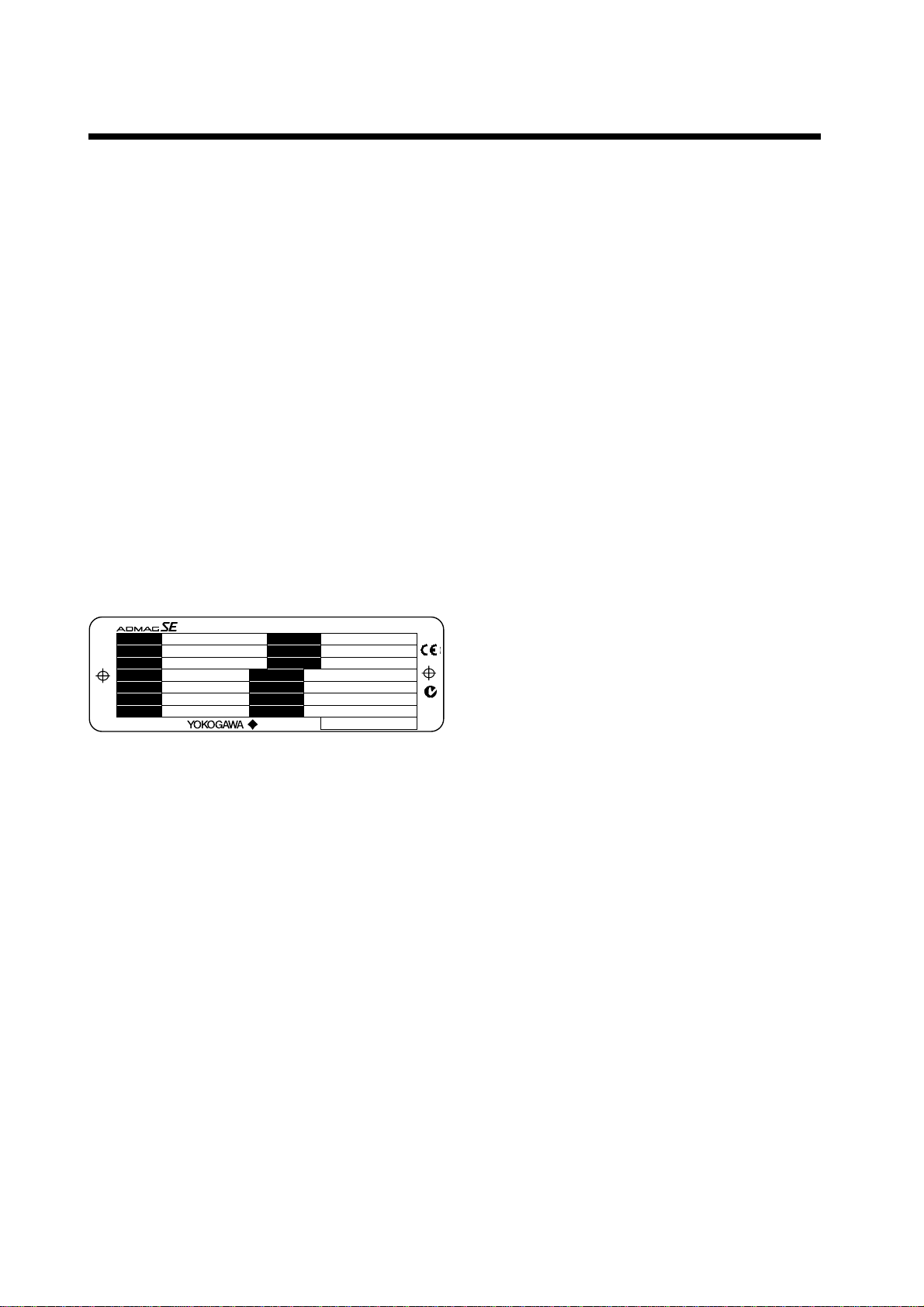
2.1 Checking Model and
Specifications
The model and specifications are shown on the Data
Plate. Please confirm the specifications between the
instrument that was delivered and the purchase order
(refer to the chapter 5. Outline).
Please let us know Model and Serial No. when making
contact with Yokogawa sales office.
SIZE
METER FACTOR
ELECTRODE
FLUID PRESS
FLUIDTEMP.
AMB.TEMP.
NO.
MAGNETIC FIOW TUBE
MODEL mm
SUFFIX
STYLE
ENCLOSURE
LINING IP67
PFA
TAG NO.
IM : User’s Manual Made in Japan
– 0.1 MPa MIN. (SEE IM)
– 40 to + 160 °C (SEE IM)
– 20 to + 60 °C SEE IM
N200
0038
Figure 2.1 Data Plate
2.2 Accessories
When the instrument is delivered, please make sure
that the following accessories are in the package.
•Centering device 1-set (for wafer type)
•Hexagonal wrench 1-piece (for special screw of
terminal cover)
2.3 Storage Precautions
In case the instrument is expected to be stored over a
long term, please give attention to the followings;
•The instrument should be stored in its original
packing condition.
•The storage location should be selected according to
the following conditions:
1) The location where it is not exposed to rain or
water.
2) The location where there is few vibration or
shock.
3) Temperature and humidity should be:
Temperature: –40 to 70˚C (–40 to 158˚F)
Humidity: 5 to 80% RH (no condensation)
Preferable ambient temperature and humidity
are 25˚C(77˚F) and about 65% RH.
2.4 Installation Location
Precautions
Please select the installation location considering the
following items to ensure long term stable operation of
the flow tube.
•Ambient Temperature:
Please avoid to install the instrument at the location
where temperature changes continuously. If the
location receives radiant heat from the plant, provide
heat insulation or improve ventilation.
•Atmospheric Condition:
Please avoid to install the instrument in an corrosive
atmosphere. In case of installing in the corrosive
atmosphere, please keep ventilating sufficiently and
prevent rain from entering the conduit.
•Vibration or shock:
Please avoid to install the instrument at the location
where there is heavy vibration or shock.
2.5 Terminal Box Reori-
entation Precautions
Please do not change the terminal box orientation at
the customer’s site. If the terminal box reorientation is
required, please contact Yokogawa office or service
center.

IM 1E10D0-01E
3-1
3. INSTALLATION
3. INSTALLATION
WARNING
This instrument must be installed by expert
engineer or skilled personnel. The procedures
described in this chapter are not permitted for
operators.
3.1 Piping Design Pre-
cautions
IMPORTANT
Please design the correct piping referring to the
followings to prevent damage for flow tube and
to keep correct measuring.
(1) Location
IMPORTANT
Please install the flow tube to the location where
it is not exposed to direct sunlight and ambient
temperature is –20 to + 60°C (–4 to 140°F)*.
* The minimum temperature is –10°C (14°F) in case
of the 40mm or larger sizes with the carbon steel
flange connection or wafer connection.
(2) Noise Rejection
IMPORTANT
The instrument should be installed away from
large electrical motors, transformers and other
power sources in order to avoid interference with
the measurement.
(3) Length of Straight Run
To keep accurate measuring, JIS B7554 “Electro
Magnetic Flow Tubes” explains about upstream piping
condition of Magnetic Flow Tubes.
We recommend to our customers about the piping
conditions shown in Figure 3.1.1 based on JIS B7554
and our piping condition test data.
Gate valve
fully open Reducer pipe Expander pipe
Tee 90°degrees bent Various types of valves
5 D or more 2 D or more 2 D or more
2 D or more
10 D or more
10 D or more5 D or more5 D or more Do not care to 0 D Do not care to 0 D
Do not care to 0 D Do not care to 0 D
F030101.EPS
D: Nominal diameter of flow tube
Figure 3.1.1 Minimum Length of Required Straight Run
NOTE
1. Nothing must be inserted or installed in the
metering pipe that may interfere with the
magnetic field, induced signal voltages, and
flow velocity distribution.
2. These straight runs may not be required on
the downstream side of flowmeter. However,
if the downstream valve or other fittings
cause channeling on the upstream side,
provide a straight run of 2 D to 3 D on the
downstream side.
(4) Liquid Conductivity
IMPORTANT
Please avoid to install the flow tube at location
where liquid conductivity is likely to be non-
uniform. Because it is possible to have bad
influences to the flow indication by non-uniform
conductivity when a chemical liquid is injected
from upstream side close to the flow tube. When
this occurs, it is recommended that chemical
application ports are installed on the downstream
side of the flow tube. In case chemicals must be
added upstream side, please keep the pipe
length enough so that liquid is properly mixed.
(BAD)
Upstream side (GOOD)
Downstream side
F030102.EPS
Figure 3.1.2 Chemical Injection
IM 1E10D0-01E
3-2
3. INSTALLATION
(5) Liquid Sealing Compound
IMPORTANT
Please give attention in using Liquid Sealing
Compound to the piping, because it brings bad
influences to measurement by flowing out and
cover the surfaces of electrode and earth-ring.
(6) Service Area
Please select the location where there is enough area to
service installing, wiring, overhaul, etc.
(7) Bypass Line
It is recommended to install the Bypass Line to
facilitate maintenance and zero adjustment.
Bypass valve
Block valve
Block
valve
F030103.EPS
Figure 3.1.3 Bypass Line
(8) Supporting the Flow Tube
CAUTION
Please avoid to support only the flow tube, but
fix pipes at first and support the flow tube by
pipes to protect the flow tube from forces caused
by vibration, shock, expansion and contraction
through piping.
(9) Piping Condition
IMPORTANT
The piping should be designed so that a full pipe
is maintained at all times to prevent loss of
signal and erroneous readings.
Please design the piping that a fluid is always filled in
the pipes. The Vertical Mounting is effective for fluids
that is easily separate or slurry settles within pipes.
In this case, please flow a fluid from bottom to up.
(GOOD)
(GOOD)
(BAD)
(BAD)
h
h>0
h>0
h
F030104.EPS
Horizontal mounting Vertical mounting
Figure 3.1.4 Filling the Pipe with Liquid
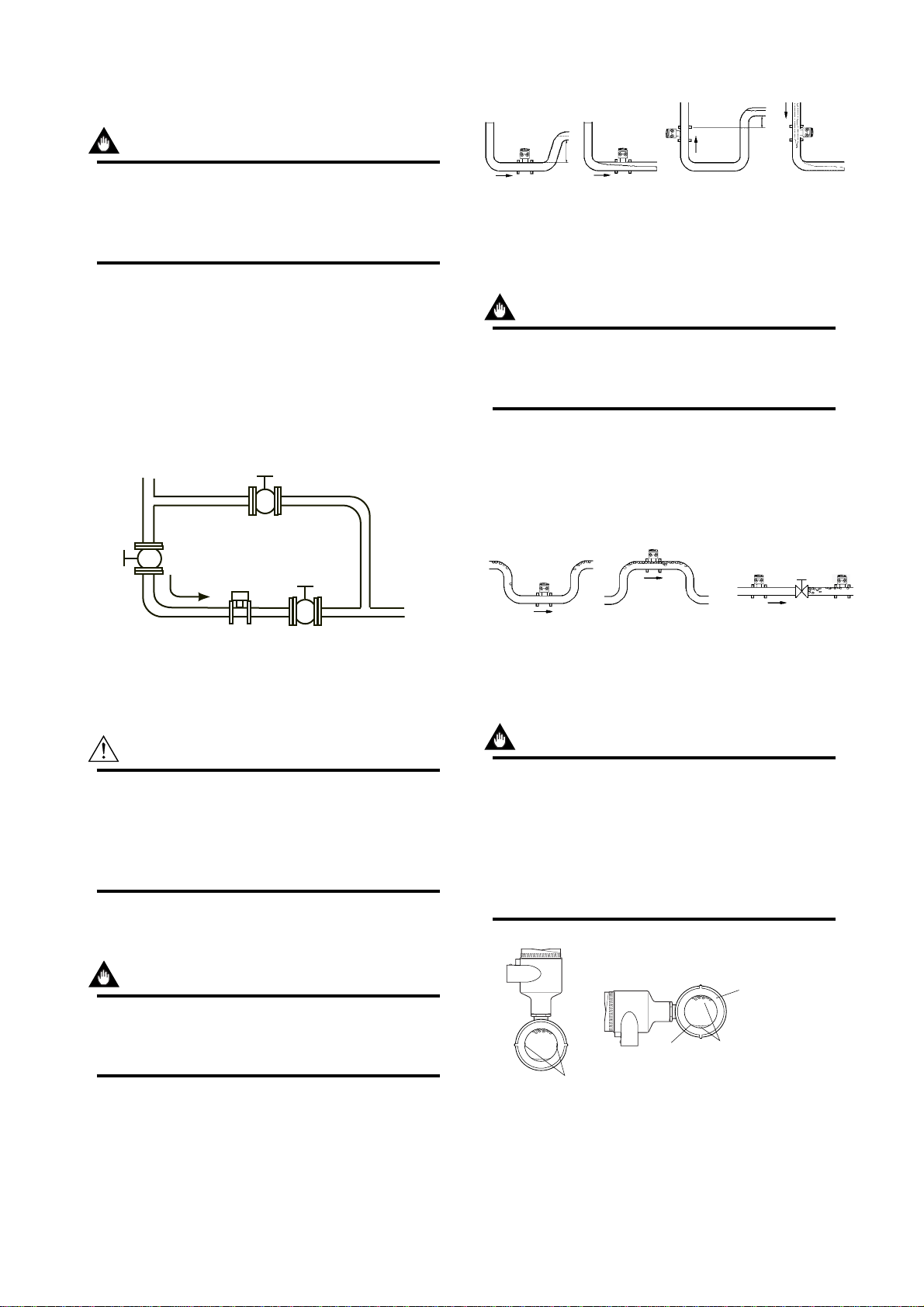
(10) No Air Bubbles
IMPORTANT
Please give attention to prevent bad influences
or measuring errors from air bubbles that gath-
ers inside measuring pipes.
In case the fluid includes air bubbles, please design the
piping that prevent to gather air bubbles. In case valves
are installed upstream of the flow tube, it is possible
that a valve causes air bubbles, please install the flow
tube upstream side of a valve.
(GOOD)
(BAD)
F030105.EPS
(BAD)
(GOOD)
Figure 3.1.5 Avoiding Air Bubbles
(11) Mounting Direction
IMPORTANT
When the electrodes are vertical to ground, the
electrode is covered with air bubbles at upper
side or slurry at downside, and it may cause the
measuring errors.
Please be sure to mount the terminal box upper
side of piping to prevent water penetration into
terminal box.
(GOOD) (BAD)
Air Bubbles
Slurry Electrodes
F030106.EPS
Electrodes
Figure 3.1.6 Mounting Direction
IM 1E10D0-01E
3-3
3. INSTALLATION
(12) Grounding
IMPORTANT
Improper grounding can have an adverse affect
on the flow measurement. Please ensure that
the instrument is properly grounded.
The electromotive force of the magnetic flow tube is
minute and it is easy to be affected by noise. And also
that reference electric potential is the same as the
measuring fluid potential. Therefore, the reference
electric potential (terminal potential) of the Flow Tube
and the Converter/Amplifier also need to be the same
as the measuring fluid. And moreover, that the poten-
tial must be the same with ground.
Please be sure to ground according to Figure 3.1.7.
600 V vinyl insulated
electric cable
(2mm
2
or larger)
Earth ring
F030107.EPS
Grounding resistance 100Ωor less
Note: See “3.4.1 Grounding”for
information on grounding.
In case earth rings are not used.
(Available only for metal piping)
In case earth rings are used.
Figure 3.1.7 Grounding
3.2 Handling Precau-
tions
WARNING
The Magnetic Flow tube is a heavy instrument.
Please be careful to prevent persons from
injuring when it is handled.
3.2.1 General Precautions
(1) Precaution for Carrying
The Magnetic Flow Tube is packed tightly. When it is
unpacked, please give attention to prevent damages to
the flow tube. And to prevent the accident during carry
to the installing location, please carry it near the
location keeping packed as it delivered.
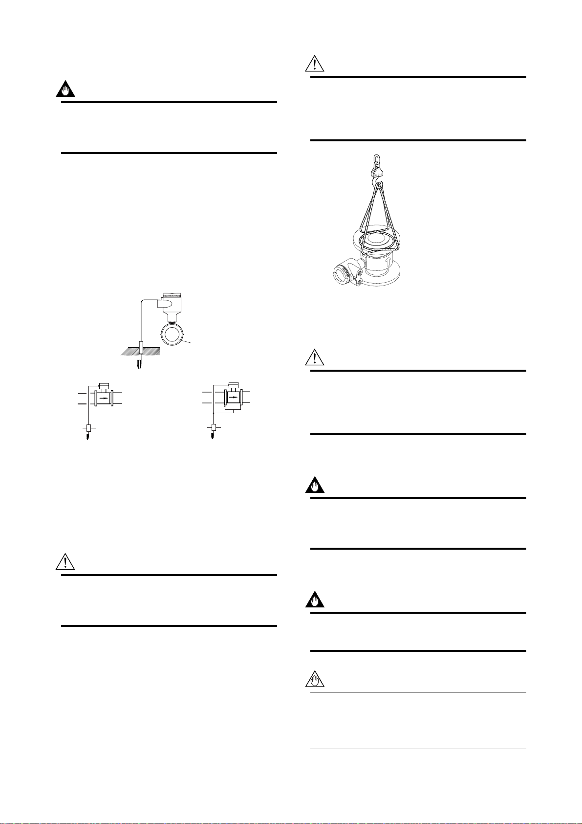
CAUTION
In case the Magnetic Flow Tube without eye-bolt
lifts up, please refer to Figure 3.2.1. Please
never lift up by using a bar through the flow
tube. It damages liner severely.
F030201.EPS
Figure 3.2.1 Vertical Lifting Sling Rigging Method
(2) Precaution for Shock
CAUTION
Care should be taken not to drop the flow tube
or subject it to excessive shock. This may lead
to liner damage which will cause inaccurate
readings.
(3) Flange Protection Covers
IMPORTANT
Please keep the protection cover (ex. corrugated
paper or anything possible to protect) attached
with flange except when mounting to the pipe.
(4) Terminal Box Cover
IMPORTANT
Please never leave the terminal box cover open
until wiring to prevent insulation deterioration.
NOTE
The terminal box cover is locked by special
screw. In case of opening the terminal box
cover, please use the Hexagonal Wrench
attached.
IM 1E10D0-01E
3-4
3. INSTALLATION
CAUTION
Be sure to lock the cover with the special screw
using the Hexagonal Wrench attached after
tightening the terminal box cover.
(5) Long-term Non-use
IMPORTANT
It is not preferable to leave the flow tube for long
term non-use after installation.
In case the flow tube is compelled to do that,
please take care of the flow tube by the follow-
ings.
•Confirmation of Sealing Condition for the Flow
Tube
Please confirm the sealing conditions of the terminal
box screw and wiring ports.
In case of the Conduit Piping, please provide the
drain plugs or waterproof glands to it to prevent that
moisture or water penetrates into the flow tube
through the conduit.
•Regular Inspections
Please inspect the sealing condition (as above
mentioned) and inside of the terminal box. And
when it is suspect that water penetration into the
inside flow tube (ex. rain fall), please inspect when
it happened.
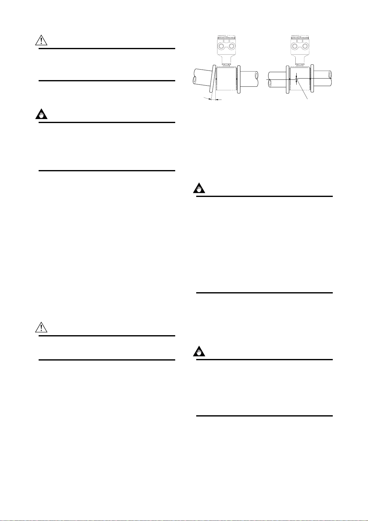
3.2.2 Flow Tube Piping
CAUTION
Mis-aligned or slanted piping can lead to leakage
and damage to flanges.
•Please correct mis-alignment or slanted piping and
improper distance between mounting flanges before
install the flow tube. (Please refer to Figure 3.2.2)
•Inside a pipeline which is newly installed, some
foreign substances (such as welding scrap or wood
chips) may exist. Please remove them by flushing
piping before mounting the flow tube.
Slant Mis-alignment
F030202.EPS
Figure 3.2.2 Slant and Mis-alignment of Flow Tube Piping
3.3 Mounting
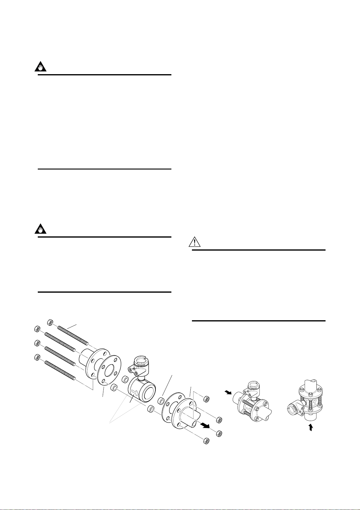
3.3.1 Nominal Diameter 15mm (0.5˝)
to 40mm (1.5˝) Wafer Type
IMPORTANT
Please use appropriate bolts and nuts according
to process connection. In case stud type of
through bolts are used, be sure outside diameter
of a shank is smaller than a thread ridge’s one.
Please use compressed non-asbestos fiber
gasket, PTFE gasket or the gasket which has
equal elasticity. In case of optional code/FRG,
please use rubber gasket or others which has
equal elasticity. Be sure the inner diameter of
the gasket does not protrude to inner piping.
(Refer to Table 3.3.6)
(1) Mounting Direction
Please mount the Magnetic Flow Tube matching the
flow direction of the fluid to be measured with the
direction of the arrow mark on the flow tube.
IMPORTANT
If it is impossible to match the direction, please
never remodel by changing direction of the
terminal box. In case the measuring fluid flows
against the arrow direction, please refer to the
section “Reversing Flow Direction” in the Instruc-
tion Manual of SE14 Magnetic Flow Converter.
(2) Mounting Centering Devices
To keep concentricity of the Flow Tube with pipes,
please mount centering devices on the Mini-Flanges of
the Flow Tube. Please give attention to the nominal
diameter and flange rating of the centering devices.
IM 1E10D0-01E
3-5
3. INSTALLATION
(3) Positioning Flow Tube
Please pass two through-bolts to adjacent holes of both
flanges and mount the Flow Tube, and pass other
through-bolts to other holes. (Refer to Figure 3.3.1) In
case stud type of through-bolts are used, position them
coming in contact centering devices with thread of
bolts.
(4) Tightening Nuts
Please tighten the bolts according to Torque Values in
Table 3.3.1. In case of PVC piping, please select
optional code /FRG, use rubber gasket and tighten with
the torque value in Table 3.3.2.
CAUTION
As the lining material is Fluorocarbon PFA, it is
possible that nuts may loose by its character as
time passes. Please tighten the nuts regularly.
Please be sure to tighten the bolts following
prescribed torque values. Please tighten the
flange bolts diagonally with the same torque
values, step by step up to the prescribed torque
value.
Through-Bolt
and nut
Flange
Mini-Flange
Gasket
F030301-1.EPS
Centering Device
2-pieces
Please use appropriate bolts and
nuts according to Process connection.
Horizontal Mounting Vertical Mounting
F030301-2.EPS
Figure 3.3.1 Mounting Procedure (Size: 15 mm(0.5") to 40
mm(1.5")
Table 3.3.1 Tightening Torque Values for Metal Piping in N-m{kgf-cm}[in-lbf]
Size mm(inch) JIS 10K JIS 20K ANSI 150 ANSI 300 DIN PN40
15(0.5)
25(1)
40(1.5)
4.5 - 6.5
{46 - 66}
[40 - 58]
14.5 - 19.0
{148 - 194}
[128 - 168]
26.0 - 31.0
{265 - 316}
[230 - 274]
4.5 - 6.5
{46 - 66}
[40 - 58]
14.5 - 19.0
{148 - 194}
[128 - 168]
26.0 - 31.0
{265 - 316}
[230 - 274]
5.0 - 7.0
{51 - 71}
[44 - 62]
12.0 - 15.0
{122 - 153}
[106 - 133]
22.0 - 25.0
{224 - 255}
[195 - 221]
5.0 - 7.0
{51 - 71}
[44 - 62]
14.5 - 19.0
{148 - 194}
[128 - 168]
30.0 - 37.0
{311 - 377}
[270 - 327]
5.0 - 6.5
{51 - 66}
[44 - 58]
12.5 - 14.0
{128 - 143}
[111 - 124]
28.5 - 31.0
{291 - 316}
[252 - 274]
*Please use compressed non-asbestos fiber gasket, PTFE gasket or the gasket which has equal elasticity.
T030301.EPS
Table 3.3.2 Tightening Torque Values for PVC Piping in N-m{kgf-cm}[in-lbf]
Size mm(inch) JIS 10K JIS 20K ANSI 150 ANSI 300 DIN PN40
15(0.5)
25(1)
40(1.5)
1.3
{13}
[12]
3.5
{36}
[31]
5.7
{58}
[50]
1.3
{13}
[12]
2.8
{29}
[25]
4.6
{47}
[41]
1.3
{13}
[12]
2.7
{28}
[24]
5.7
{58}
[50]
*Please select optional code /FRG and use rubber gasket or others which has equal elasticity. T030302.EPS
IM 1E10D0-01E
3-6
3. INSTALLATION
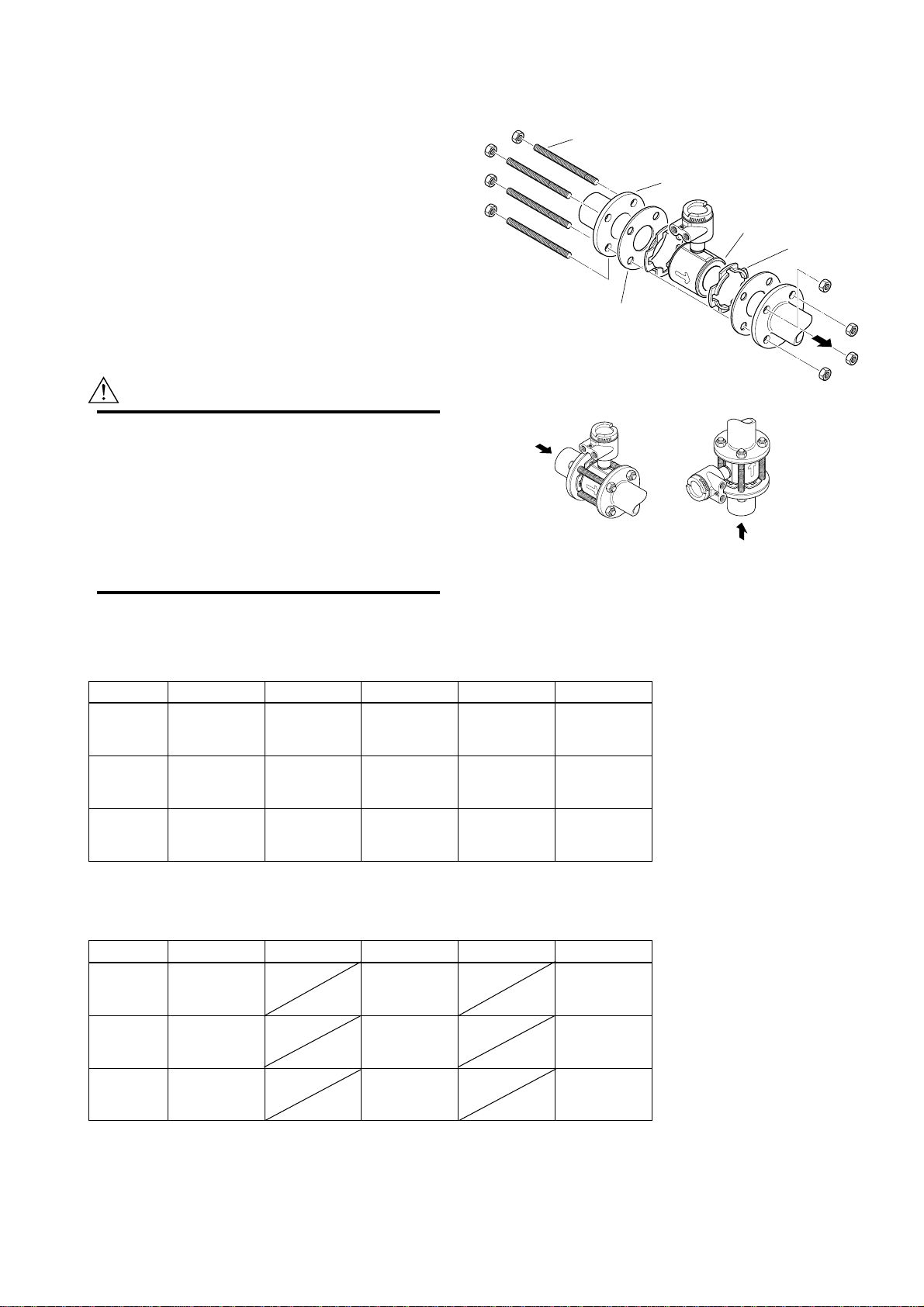
3.3.2 Nominal Diameter 50 mm(2˝) to
200 mm(8˝) Wafer Type
IMPORTANT
Please use appropriate bolts and nuts according
to process connection. In case stud type of
through bolts are used, be sure outside diameter
of a shank is smaller than a thread ridge’s one.
Please use compressed non-asbestos fiber
gasket, PTFE gasket or the gasket which has
equal elasticity. In case of optional code/FRG,
please use rubber gasket or others which has
equal elasticity. Be sure the inner diameter of
the gasket does not protrude to inner piping.
(Refer to Table 3.3.6)
(1) Mounting Direction
Please mount the Magnetic Flow Tube matching the
flow direction of the fluid to be measured with the
direction of the arrow mark on the flow tube.
IMPORTANT
If it is impossible to match the direction, please
never remodel to change direction of the termi-
nal box. In case the measuring fluid flows
against the arrow direction, please refer to the
section “Reversing Flow Direction” in the Instruc-
tion Manual of SE14 Magnetic Flow Converter.
(2) Mounting Centering Devices
To keep concentricity between the Flow Tube and
pipes, centering devices must be used. Pass two
through-bolts through the four centering devices (two
for each) and lower adjacent holes of both flanges.
(Refer to Figure 3.3.2)
Please give attention to the nominal size and flange
ratings of the centering devices. (Refer to Table 3.3.5)
(3) Positioning Flow Tube
Position the Flow Tube coming in contact four center-
ing devices with Mini-Flanges. At this time, pay
attention to avoid four centering devices come in
contact with Housing. In case stud type of through-
bolts are used, position them coming in contact four
centering devices with thread of the bolts. (Refer to
Figure 3.3.2) After positioning the Flow Tube, pass
remaining through-bolts to remaining holes.
(4) Tightening Nuts
Please tighten the bolts according to Torque Values in
Table 3.3.3. In case of PVC piping, please select
optional code/FRG, use rubber gasket and tighten with
the torque value in Table 3.3.4.
CAUTION
As the lining material is Fluorocarbon PFA, it is
possible that nuts loose by its character as time
passes. Please tighten the nuts regularly.
Please be sure to tighten the bolts following
prescribed torque values. Please tighten the
flange bolts diagonally with the same torque
values, step by step up to the prescribed torque
value.
Through-Bolt
and nut
Centering Device
4-piece
Flange
Gasket
Please use appropriate bolts and
nuts according to process connection.
Housing
Mini-Flange
F030302-1.EPS
Figure 3.3.2 Mounting Procedure
Horizontal Mounting Vertical Mounting
F030302-2.EPS

IM 1E10D0-01E
3-7
3. INSTALLATION
Table 3.3.3 Tightening Torque Values for Metal Piping in N-m{kgf-cm}[in-lbf]
Size mm(inch) JIS 10K JIS 20K ANSI 150 ANSI 300 DIN PN10
50(2)
80(3)
100(4)
150(6)
200(8)
250(8)
300(8)
35.0 - 39.5
{357 - 403}
[310 - 350]
27.5 - 32.5
{281 - 332}
[243 - 288]
40.0 - 42.5
{408 - 434}
[354 - 376]
65.0 - 94.0
{663 - 959}
[575 - 832]
57.0 - 84.0
{581 - 857}
[504 - 743]
98.0 - 128.0
{996 - 1307}
[867 - 1133]
85.0 - 108.0
{871 - 1098}
[752 -956]
16.5 - 19.5
{168 - 199}
[146 - 173]
33.0 - 41.0
{337 - 418}
[292 - 363]
48.0 - 53.5
{490 - 546}
[425 - 473]
43.0 - 68.0
{439 - 694}
[381 - 602]
61.0 - 92.0
{622 - 938}
[540 - 814]
35.0 - 39.5
{357 - 403}
[310 - 350]
60.0 - 65.5
{612 - 668}
[531 - 580]
40.5 - 42.5
{413 - 434}
[358 - 376]
68.0 - 100.0
{694 - 1020}
[602 - 885]
69.0 - 101.0
{704 - 1030}
[611 - 894]
89.0 - 130.0
{909 - 1329}
[788 - 1150]
106.0 - 146.0
{1083 -1489}
[938 - 1292]
16.5 - 19.5
{168 - 199}
[146 - 173]
32.0 - 39.0
{326 - 398}
[283 - 345]
47.0 - 51.0
{479 - 520}
[416 - 451]
41.0 - 60.0
{418 - 612}
[363 - 531]
65.0 - 93.0
{663 - 949}
[575 - 823]
94.0 - 125.0
{959 - 1275}
[832 - 1106]
57.0 - 84.0
{581 - 857}
[504 - 743]
108.0 - 131.0
{1103 - 1339}
[956 - 1159]
DIN PN16
27.5 - 32.5
{281 - 332}
[243 - 288]
40.0 - 42.5
{408 - 434}
[354 - 376]
65.0 - 94.0
{663 - 959}
[575 - 832]
58.0 - 84.0
{592 - 857}
[513 - 743]
DIN PN40
39.0 - 39.5
{398 - 403}
[345 - 350]
*Please use compressed non-asbestos fiber gasket, PTFE gasket or the gasket which has equal elasticity.
T030303.EPS
Table 3.3.4 Tightening Torque Values for PVC Piping in N-m{kgf-cm}[in-lbf]
Size mm(inch) JIS 10K JIS 20K ANSI 150 ANSI 300 DIN PN10
50(2)
80(3)
100(4)
150(6)
200(8)
8.2
{84}
[73]
6.2
{63}
[55]
8
{82}
[71]
19.8
{202}
[175]
17.5
{179}
[155]
*Please select optional code /FRG and use rubber gasket or others which has equal elasticity.
8.2
{84}
[73]
12.4
{127}
[110]
8.1
{83}
[72]
18.9
{193}
[167]
25.1
{256}
[222]
DIN PN16 DIN PN40 JIS G3451
F12(75M)
6.2
{63}
[55]
8
{82}
[71]
19.8
{202}
[175]
17.5
{179}
[155]
12.3
{126}
[109]
16.1
{164}
[142]
21.6
{220}
[191]
28.7
{293}
[254]
8.2
{84}
[73]
26.2
{267}
[232]
T030304.EPS
Table 3.3.5 Centering Device Identification Table 3.3.6 Earth Ring Inside Diameter
Size mm(inch) JIS 10K
50(2)
80(3)
100(4)
150(6)
200(8)
250(10)
300(12)
B
B
B
K
K
C
C
JIS 20K
B
F
F
L
L
-
-
ANSI 150
B
F
C
K
L
K
K
ANSI 300
F
C
H
M
M
-
-
DIN PN10
-
-
-
-
K
C
C
DIN PN16
-
G
F
K
K
-
-
DN40
F
-
-
-
-
-
-
T030305.EPS
*Each Centering Device is engraved a character as identification.
Size Earth Ring Inside Diameter
15(0.5)
25(1)
40(1.5)
50(2)
80(3)
100(4)
150(6)
200(8)
250(10)
300(12)
350(14)
400(16)
15(0.59)
28(1.10)
41(1.61)
53(2.09)
81(3.19)
102(4.02)
146.1(5.75)
193.6(7.62)
323.4(12.73)
373.5(14.70)
Unit:mm(inch)
* Please ensure that the I.D. of the gasket does not protrude
into the I.D. of the earth ring inside diameter.
(This dimension is also applied to when no earth ring is used.)
T030306.EPS
wafer:243.7(9.6), flange:239.1(9.41)
wafer:294.7(11.6), flange:291.3(11.47)
IM 1E10D0-01E
3-8
3. INSTALLATION
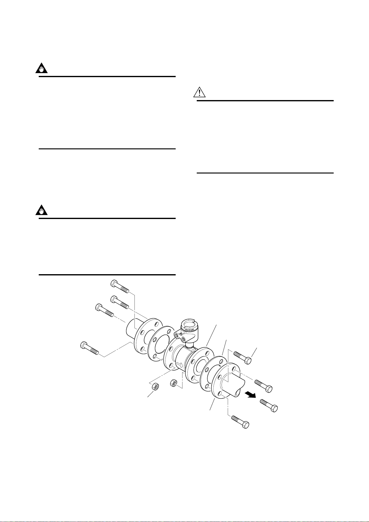
3.3.3 Nominal Diameter 15 mm (0.5˝)
to 400 mm (16˝) Flange Type
IMPORTANT
Please use appropriate bolts and nuts according
to process connection. Please use compressed
non-asbestos fiber gasket, PTFE gasket or the
gasket which has equal elasticity. In case of
optional code/FRG, please use rubber gasket or
others which has equal elasticity. Be sure the
inner diameter of the gasket does not protrude to
inner piping.(Refer to Table 3.3.6)
(1) Mounting Direction
Please mount the Magnetic Flow Tube matching the
flow direction of the fluid to be measured with the
direction of the arrow mark on the flow tube.
IMPORTANT
If it is impossible to match the direction, please
never remodel to change direction of the termi-
nal box. In case the measuring fluid flows
against the arrow direction, please refer to the
section “Reversing Flow Direction” in the Instruc-
tion Manual of SE14 Magnetic Flow Converter.
Flange
(Flow Tube)
Flange
(Piping side)
Nut
Gasket
Bolt
F030303.EPS
Please use appropriate bolts and nuts
according to Process connection.
Figure 3.3.3 Mounting Procedure (Size: 15 mm (0.5") to 400 mm (16"))
(2) Tightening Nuts
Please tighten the bolts according to Torque Values in
Table 3.3.7. In case of PVC piping, please select
optional code/FRG, use rubber gasket and tighten with
the torque value in Table 3.3.8.
CAUTION
As the lining material is Fluorocarbon PFA, it is
possible that bolts loose by its character as time
passes. Please tighten the nuts regularly.
Please be sure to tighten the bolts following
prescribed torque values. Please tighten the
flange bolts diagonally with the same torque
values, step by step up to the prescribed torque
value.

IM 1E10D0-01E
3-9
3. INSTALLATION
Table 3.3.7 Tightening Torque Values for Metal Piping in N-m{kgf-cm} [in-lbf]
Size mm(inch) JIS 10K JIS 20K ANSI 150 ANSI 300 DIN PN10
15(0.5)
25(1)
40(1.5)
50(2)
80(3)
100(4)
150(6)
200(8)
250(10)
300(12)
350(14)
400(16)
4.5 - 6.5
{46 - 66}
[40 - 58]
13.5 - 19.0
{138 - 194}
[119 - 168]
24.0 - 31.0
{245 - 316}
[212 - 274]
31.0 - 39.5
{316 - 403}
[274 - 350]
23.5 - 32.5
{240 - 332}
[208 - 288]
32.5 - 42.5
{332 - 434}
[288 - 376]
65.0 - 94.0
{663 - 959}
[575 - 832]
57.0 - 84.0
{581 - 857}
[504 - 743]
141.8 - 174
{1450 - 1780}
[1261 - 1548]
113.4 - 138.8
{1160 - 1420}
[1008 - 1235]
157.4 - 183.8
{1610 - 1880}
[1399 - 1634]
242.5 - 261.1
{2480 - 2670}
[2156 - 2321]
4.5 - 6.5
{46 - 66}
[40 - 58]
13.5 - 19.0
{138 - 194}
[119 - 168]
24.0 - 31.0
{245 - 316}
[212 - 274]
15.0 - 19.5
{153 - 199}
[133 - 173]
28.5 - 41.0
{291 - 418}
[252 - 363]
40.0 - 53.5
{408 - 546}
[354 - 473]
43.0 - 68.0
{439 - 694}
[381 - 602]
61.0 - 92.0
{622 - 938}
[540 - 814]
153.1 - 182.8
{1570 - 1870}
[1365 - 1625]
124.2 - 145.7
{1270 - 1490}
[1104 - 1295]
4.5 - 7.0
{46 - 71}
[40 - 62]
11.5 - 15.0
{117 - 153}
[102 - 133]
20.0 - 25.0
{204 - 255}
[177 - 221]
32.0 - 39.5
{326 - 403}
[283 - 350]
53.5 - 65.5
{546 - 668}
[473 - 580]
34.5 - 42.5
{352 - 434}
[305 - 376]
68.0 - 100.0
{694 - 1020}
[602 - 885]
69.0 - 101.0
{704 - 1030}
[611 - 894]
144.7 - 177
{1480 - 1810}
[1286 - 1573]
163.6 - 187.7
{1670 - 1920}
[1452 - 1669]
245- 284.5
{2510 - 2910}
[2182 - 2530]
252.3 - 275.7
{2580 - 2820}
[2243 - 2452]
4.5 - 7.0
{46 - 71}
[40 - 62]
14.0 - 19.0
{143 - 194}
[124 - 168]
28.0 - 37.0
{286 - 377}
[248 - 327]
15.0 - 19.5
{153 - 199}
[133 - 173]
28.5 - 39.0
{291 - 398}
[252 - 345]
40.0 - 51.0
{408 - 520}
[354 - 451]
41.0 - 60.0
{418 - 612}
[363 - 531]
65.0 - 93.0
{663 - 949}
[575 - 823]
125.1 - 151.5
{1280 - 1550}
[1112 - 1347]
153.5 - 180.9
{1570 - 1850}
[1365 - 1608]
94.0 - 125.0
{959 - 1275}
[832 - 1106]
135.9 - 164.3
{1390 - 1680}
[1208 - 1460]
154.5 - 199.5
{1580 - 2040}
[1373 - 1773]
151.5 - 192.6
{1550 - 1970}
[1347 - 1712]
247.4 - 331.5
{2530 - 3390}
[2199 - 2947]
DIN PN16
23.5 - 32.5
{240 - 332}
[208 - 288]
33.0 - 42.5
{337 - 434}
[292 - 376]
65.0 - 94.0
{663 - 959}
[575 - 832]
58.0 - 84.0
{592 - 857}
[513 - 743]
153.5 - 175
{1570 - 1790}
[1365 - 1556]
175 - 213.2
{1790 - 2180}
[1556 - 1896]
DIN PN40
4.5 - 6.5
{46 - 66}
[40 - 58]
11.5 - 14.0
{117 - 143}
[102 - 124]
25.5 - 31.0
{260 - 316}
[226 - 274]
34.5 - 39.5
{352 - 403}
[305 - 350]
JIS F12(75M)
51.0 - 65.5
{520 - 668}
[451 - 580]
72.0 - 85.0
{734 - 867}
[637 - 752]
68.0 - 100.0
{694 - 1020}
[602 - 885]
69.0 - 101.0
{704 - 1030}
[611 - 894]
214.1 - 270.9
{2190 - 2770}
[1904 - 2408]
189.7 - 249.3
{1940 - 2550}
[1686 - 2217]
273.8 - 325.6
{2800 - 3330}
[2434 - 2895]
312.9 - 395
{3200 - 4050}
[2782 - 3521]
*Please use compressed non-asbestos fiber gasket, PTFE gasket or the gasket which has equal elasticity. T030307.EPS
Table 3.3.8 Tightening Torque Values for PVC Piping in N-m{kgf-cm} [in-lbf]
Size mm(inch) JIS 10K JIS 20K ANSI 150 ANSI 300 DIN PN10
15(0.5)
25(1)
40(1.5)
50(2)
80(3)
100(4)
150(6)
200(8)
1.3
{13}
[12]
3.5
{36}
[31]
5.7
{58}
[50]
8.2
{84}
[73]
6.2
{63}
[55]
8
{82}
[71]
19.6
{200}
[173]
17.5
{179}
[155]
*Please select optional code /FRG and use rubber gasket or others which has equal elasticity.
DIN PN16 DIN PN40 JIS G3451
F12(75M)
6.2
{63}
[55]
8
{82}
[71]
19.6
{200}
[173]
17.5
{179}
[155]
12.3
{126}
[109]
16.1
{164}
[142]
21.6
{220}
[191]
28.7
{293}
[254]
1.3
{13}
[12]
2.7
{28}
[24]
5.7
{58}
[50]
8.2
{84}
[73]
26.2
{267}
[232]
1.3
{13}
[12]
2.8
{29}
[25]
4.6
{47}
[41]
8.2
{84}
[73]
12.4
{127}
[110]
8.1
{83}
[72]
18.8
{192}
[166]
25.1
{256}
[222]
T030308.EPS

IM 1E10D0-01E
3-10
3. INSTALLATION
3.4 Wiring Precautions
This section is described wiring only for flow tube
side. Please see "Wiring" in SE14 Magnetic Flow
Converter Instruction Manual for converter side.
CAUTION
Confirm that all connections are corrected before
applying power to the instrument. Improper
wiring may damage the flow tube or converter.
NOTE
The terminal box cover is locked by special
screw. In case of opening the terminal box
cover, please use the Hexagonal Wrench
attached.
CAUTION
Be sure to lock the cover with the special screw
using the Hexagonal Wrench attached after
tightening the terminal box cover.
3.4.1 Grounding
CAUTION
Please be sure to connect function grounding of
ADMAG SE with cable of 2mm2or larger cross
section in order to prevent the influence of
external noise. And further connect the
grounding wire to the mark (100Ωor less).
3.4.2 General Precautions
Please give attention to the followings in wiring.
CAUTION
•Please pay attention to avoid the cable is
bended excessively.
•Please do not connect cables outdoors in case
of rain to prevent damages from dew formation
and to keep insulation inside the terminal box
of the flow tube.
•Please do not splice the cable between a flow
tube and a converter if it is too short. Please
replace the short cable with the cable which is
appropriate length wholly.
•The all cable ends are to be provided with
round crimp-on terminal.
•The signal cables must be routed in separate
steel conduit tubes or flexible tubes.
•Please keep conduit or flexible tube water-tight
using sealing tape.
•Please ground each of a flow tube and a
converter separately.
•Please cover each shield of the signal cable
with PVC tube or PVC tape to avoid contacting
between two shields; shield and case.
•When waterproof glands or union equipped
waterproof glands are used, the glands must be
properly tightened to keep the box watertight.
•Please be sure to fully tighten the terminal box
cover before the power is turned on.
•Please be sure to turn off the power before
opening the terminal box cover.
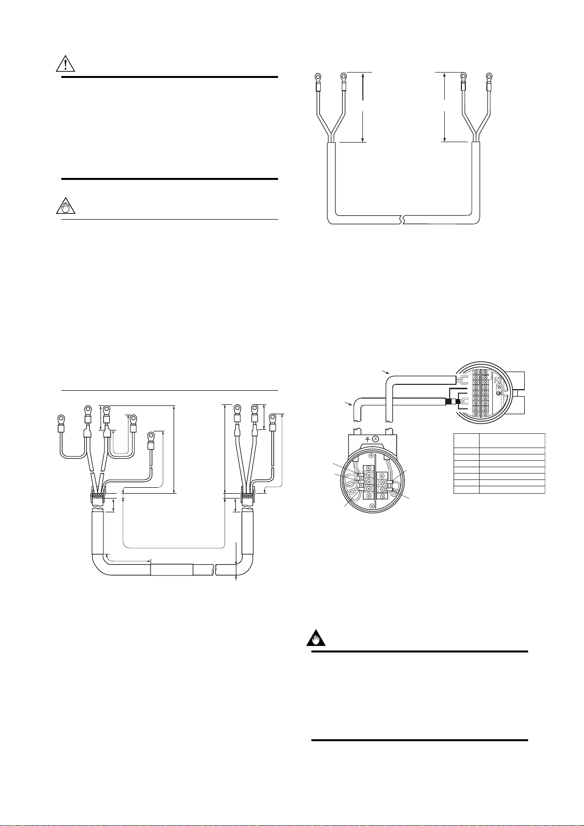
3.4.3 Cable Types
(1) Dedicated Signal Cable(AM011)
The flow signal is transmitted via this dedicated cable.
The cable is constructed with double shielding over the
two conductors, and used heat-resistant vinyl as the
outer jacket material.
Finished diameter: 10.5 mm (0.413in.)
Maximum length: 300 m (984 ft.)
Maximum temperature: 80°C (176°F)
Figure 3.4.1 Dedicated Signal Cable AM011
IMPORTANT
If the cable is longer than required, cut off any
extra length, rather coiling it up, and terminate
the conductors as shown in Figure 3.4.2. Avoid
using intermediate terminal boards to extend the
cable length, or this will interrupt the shielding.
IM 1E10D0-01E
3-11
3. INSTALLATION
CAUTION
Since A, B, SA, SB, and C all operate at differ-
ent electrical potentials, securely insulate them
from each other so they do not touch.
The shields must not be allowed to touch each
other or to touch the case.
Cover each shield with vinyl tube or wrap in vinyl
tape.
NOTE
Conductors A and B carry the signal from the
electrodes, and C is at the potentials of the liquid
it self (signal common) . Shields SA and SB are
kept at the same potentials as the individual
electrodes (these are actively driven shields).
This is done to reduce the effect of the distrib-
uted capacitance of the cable at long cable
length. Note that, since the signals from the
individual electrodes are impedance converted
inside the converter, errors will result if they
come in contact with any other component.
Great care must be taken in the cable end
treatment.
20 (0.8)
ø10.5 (0.4)
AM011*A
L (SPECIFIED LENGTH)
150
(5.9)
8 (0.3) Max.
150
(5.9)
80 (3.15)
70 (2.76)
90 (3.5)
55 (2.2)
90 (3.5)
50 (1.97)
25 (0.98)
SA
SB
A
C
B
A
C
B
8 (0.3) Max.
(WHITE) (BLACK) (RED)
(WHITE) (BLACK) (RED)
Unit : mm(inch)
F030402.EPS
On the converter
side
On the flow tube
side
Figure 3.4.2 Treatment of Dedicated Signal Cable
(2) Excitation Cable
Please use Polyvinyl chloride insulated and sheathed
control cables (JIS C3401) or Polyvinyl chloride
insulated and sheathed portable power cables (JIS
C3312) or equivalents.
Outer Diameter
•6.5 to 12mm in diameter (10.5 to 11.5 mm for
waterproof gland / ECG, /ECU)
Nominal Cross Section
•Single wire; 0.5 to 2.5mm2, Stranded wire; 0.5 to
2.5mm2
60
(2.4) 85
(3.3)
EX1
EX2
EX1
EX2
On the converter side On the flow tube side
F030403.EPS
Unit: mm (inch)
Figure 3.4.3 End Treatment of Excitation Cable
3.4.4 Connnection to SE14 Magnetic
Flow Converter
Flow Tube Model SE100DJ/EJ, SE200DJ/EJ
and SE300DJ/EJ
Connect the flow tube and converter in the following
method.
EX2
EX1
F030404.EPS
A
B
C
SA (See Note below)
A
SB (See Note below)
C
EX1
EX2
BA
C
EX1
EX2
B
Dedicated Cable
AM011-4
Converter
Terminals
Connected Terminals
Flowtube SE100DJ/EJ,
SE200DJ/EJ and SE300DJ/EJ
Note: Terminate those shielding wire
terminals using tape.
Excitation Cable
Magnetic Flow Tube
SE100DJ/EJ, SE200DJ/EJ and SE300DJ/EJ
Magnetic Flow Converter
SE14
P- P+I- I+ L/+ N/-
PLS/ALMOUTCUROUTPOWERSUPPLY
EX1 EX2 C SAA B SB
G
!
Figure 3.4.4 Connection
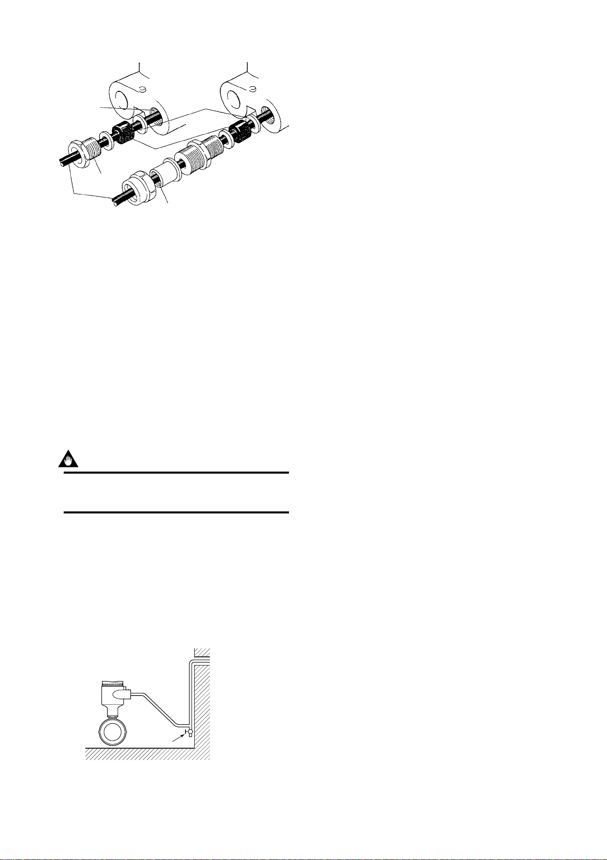
3.4.5 Wiring Ports
Please select the most suitable standard of wiring
procedure for the wiring ports by customer’s own.
A : Using the Waterproof Gland
IMPORTANT
To prevent water or condensate from entering
the converter housing, waterproof glands are
recommended. Do not over-tighten the glands or
damage to the cables may result. Tightness of
the gland can be checked by confirming that the
cable is held firmly in place.
IM 1E10D0-01E
3-12
3. INSTALLATION
G1/2 female
G1/2 female
F030405.
Tightening gland
Cable
Gasket
Waterproof gland
Optional specification code: /ECG Waterproof gland with union joint
Optional specification code: /ECU
Washer
Figure 3.4.5 Waterproof Gland
B : Insulation Check
After wiring is completed, check insulation of the
following terminals together with the wiring under the
condition of the converter side wiring terminals
disconnected.
Between terminal EX1 and terminal A, B, C
Between terminal C and terminal A, B
Between terminal A and terminal B
Between terminal EX1 and ground
Between terminal EX2 and ground
All insulation measurements must be performed with a
500V megger. Insulation resistances must be 100MΩ
or more each.
IMPORTANT
Be sure to disconnect the cables at the terminal
of the converter when checking insulation.
C : Conduit Wiring
In case of conduit wiring, please use the waterproof
gland to prevent water flowing through the conduit
pipe into the wiring connection.
Please slope the conduit pipe down, and install a drain
valve at the low end of the vertical pipe.
Please open the drain valve regularly.
Drain valve
F030406.EPS
Figure 3.4.6 Conduit Wiring
IM 1E10D0-01E
4-1
4. MAINTENANCE
4. MAINTENANCE
WARNING
This instrument must be repaired or mainte-
nance-serviced by expert engineer or skilled
personnel. The procedures described in this
chapter are not permitted for operators.
Regular maintenance and inspection should be carried
out to fully utilize all functions and to obtain maximum
performance from the magnetic flowmeter.
4.1 Regular Inspection
Items
(1)Inspection of moisture-proofing inside the
terminal box: Once/year
(2)Refastening of piping joint screws: About
twice/year
(3)Inspection of electrodes and lining (in case
of adhesive and/or abrasive fluid, etc.)
Determine the period of regular inspection as
necessary.
4.2 Trouble Shooting
Since the ADMAG SE magnetic flowmeter has “self
diagnostic functions”, if a failure occurs, it is displayed
on the SE14 magnetic flow converter. Please refer to
Instruction Manual of SE14 magnetic flow converter.
IMPORTANT
Be sure to disconnect the cables at the terminals
of the flow tube when checking.
(1) Excitation Coil Check
Check that the resistance between terminals EX1 and
EX2 in the terminal box is 150 Ωor less with a
multimeter. If it is not, coils may be broken down, and
replacement or repair of the flow tube is needed.
(2) Insulation Resistance Check
Check the insulation resistances in accordance with the
tables below. If one of them falls below the value in
the tables, replacement or repair of the flow tube is
needed.
Coil Circuit
Checking is possible even if the pipe is filled with
fluid.
TestTerminals TestVoltage Specification
Between Terminals EX1 and C 500 V DC 1MΩor more
T0401.EPS
Signal Circuit
Be sure to empty and dry the pipe inside, and release
wiring connection of converter side before checking.
TestTerminals TestVoltage Specification
Between Terminals A and C
Between Terminals B and C 500 V DC 100MΩor more for each
T0402.EPS
IM 1E10D0-01E
5-1
5. OUTLINE
5. OUTLINE
■STANDARD SPECIFICATIONS
Protection: IP67, NEMA 4X, JIS C0920 water tight type
Size in mm (inch):
15 (0.5), 25 (1), 40 (1.5), 50 (2), 80 (3), 100 (4),
150 (6), 200 (8), 250 (10), 300 (12), 350 (14), 400 (16)
Coating:
Terminal Box:
Polyurethane corrosion-resistant coating,
Deep sea moss green (Munsell 0.6Y3.1/2.0)
• Terminal box is coated for all type
Body:
Polyurethane corrosion-resistant coating,
Deep sea moss green (Munsell 0.6Y3.1/2.0)
• All sizes of carbon steel flange type
• 150 and 200 mm of wafer type
No coating
• 15 to 100mm of stainless steel flange type
• 15 to 100mm of wafer type
Flow Tube Material:
Size 15 to 100mm (0.5 to 4 in.)
Housing : Stainless steel
(15mm:SCS11, 25 to100mm:SUS304)
Mini-flange for wafer conn. : Stainless steel
(SUS430)
Flange : Carbon steel (SS400) or stainless steel
(SUS304)
Pipe : Stainless steel
(15 to 25mm:SCS13, 40 to 100mm:
SUS304)
Terminal box : Aluminum alloy
Size 150 to 400mm (6 to 16 in.)
Housing : Carbon steel (SS400)
Mini-flange for wafer conn. : Carbon steel
(SS400)
Flange : Carbon steel (SS400) or stainless steel
(SUS304)
Pipe : Stainless steel (SUS304)
Terminal box : Aluminum alloy
Wetted Part Material :
Lining : Fluorocarbon PFA
Elecctrode : Stainless steel (SUS316L), Hastelloy
C (equivalent to Hastelloy C-276)
Titanium, Tantalum, Platinum-Iridium,
Tungsten Carbide.
Earth Ring : • Size 15 to 200mm
Stainless steel (SUS316), Hastelloy C
(equivalent to Hastelloy C-276),
Titanium, PFA lining + Earth
electrode*.
*Earth Electrode: Tantalum,
Platinum-Iridium.
• Size 250, 300mm
Stainless steel(SUS316), Hastelloy C
(equivalent to Hastelloy C-276),
Titanium
• Size 350, 400mm
Stainless steel (SUS316)
Note :Hastelloy is a registered trademark of Haynes
International Inc.
Gasket :
• VALQUA#4010 ; Fluoro rubber, viton (between
flow tube body and earth ring; for optional
code/FRG)
• Non-asbestos joint sheet sheathed with fluoro
resin PTFE (between earth ring and process
flange; for optional code /BSF)
* Other gaskets between flow tube and earth ring;
• VALQUA#4010(Mixing#RCD970) ; Alkari
resistance gasket for PVC piping(Fluoro
rubber)
• VALQUA#4010(Mixing#RCD470) ; Acid
resistance gasket for PVC piping(Fluoro
rubber)
ContactYOKOGAWA office.(Refer toTI 1E6A0-06E)
Electrode Construction: External insertion type.
Electrical Connection:
ANSI 1/2NPT female, DIN Pg13.5 female,
ISO M20 X 1.5 female, JIS G1/2 female.
■STANDARD pERFORMANCE
Accuracy :
Size in mm
(inch) Span in m/s
(ft/s) Accuracy
15 to 400
(0.5 to 16)
T01.EPS
0.25% of span
(at indications below 50% of span)
0.5% of rate
(at indications 50% of span or more)
0.5% of span
0.3 to 1
(1 to 3)
1 to 10
(3 to 33)
Repeatability: 0.1% of flowrate(minimum 1mm/s)
Maximum Power Consumption: 11W (incl.converter)
Insulation Resistance:
• 100MW between excitation terminal(EX1) and
signal terminals(A, B and C) at 500V DC.
• 100MW between common terminal(C) and signal
terminals(A and B) at 500V DC.
• 100MW between signal terminal (A) and signal
terminal(B) at 500V DC.
Withstand Voltage:
• 1000V AC between excitation terminals (EX1 and
EX2) and ground terminal(G) for 1 minute.
• 500V AC between signal terminals(A and B) and
ground terminal(G) for 1 minute.(for /KF2, /FF1)
• 2000V AC between signal terminals(A and B) and
excitation terminals(EX1 and EX2) for 1 minute.
(for /KF2, /FF1)
CAUTION
When performing the Voltage Breakdown Test,
Insulation Resistance Test or any unpowered
electrical test, wait 10 seconds after the power
supply is turned off before removing the hous-
ing cover. Be sure to remove the Short Bar at
terminal “G”. After testing, return the Short Bar
to its correct position. Screw tightening torque
should be 1.18N-m(0.88ft-lb)or more, because
the G-terminal is thought as a protective
grounding and should conform to the Safety
Requirements.
IM 1E10D0-01E
5-2
5. OUTLINE
Safety Requirement Standard:
IEC1010, EN61010
EMC Conformity Standard:
EN61326
EN61000-3-2, EN61000-3-3
AS/NZS 2064
■NORMAL OPERATING CONDITIONS
Ambient Temperature: -20 to 60 °C (-4 to 140 °F)
Note :The minimum temperature is -10 °C (14°F) in case
of the 40 mm or larger sizes with the carbon steel
flange connection or wafer connection.
Ambient Humidity: 5 to 95%RH (no condensation)
Altitude at installation side: Max.2000m above sea
level
Installation category based on IEC1010: II(See Note)
Pollution level based on IEC1010: 2(See Note)
Note: • The “Installation category” implies the regulation
for impulse withstand voltage. It is also called the
“Overvoltage category”.“II” applies to electrical
equipment.
• “Pollution level” describes the degree to which a
solid, liquid or gas which deteriorates dielectric
strength is adhering. “2” applies to a normal
indoor atmosphere.
Fuse: 2A 250V (Time-Lag type)
Fluid Conductivity: 5µS/cm or larger
*In case that size 250 or 300mm is used for high conductivity
fluid (ex. caustic soda, seawater), please use the flange type.
Measurable Flow Rate Range:
MIN. Range
@0.3m/s MAX. Range
@10m/s
15
25
40
50
80
100
150
200
250
300
350
400
0.1909
0.5302
1.3572
2.1206
5.429
8.483
19.086
33.93
53.02
76.35
103.91
135.72
Size
6.361
17.671
45.23
70.68
180.95
282.74
636.1
1,130.9
1,767.1
2,544.6
3,463
4,523
SI Units (Size : mm, Flowrate : m
3
/h)
MIN. Range
@1.0ft/s MAX. Range
@33ft/s
0.5
1
1.5
2
3
4
6
8
10
12
14
16
0.6024
2.4095
5.422
9.638
21.685
38.56
86.74
154.21
240.95
347.0
472.3
616.9
T02.EPS
Size
20.078
80.31
180.70
321.2
722.8
1,285.0
2,891.3
5140
8031
11,565
15,741
20,560
English Units (Size : inch, Flowrate : GPM)
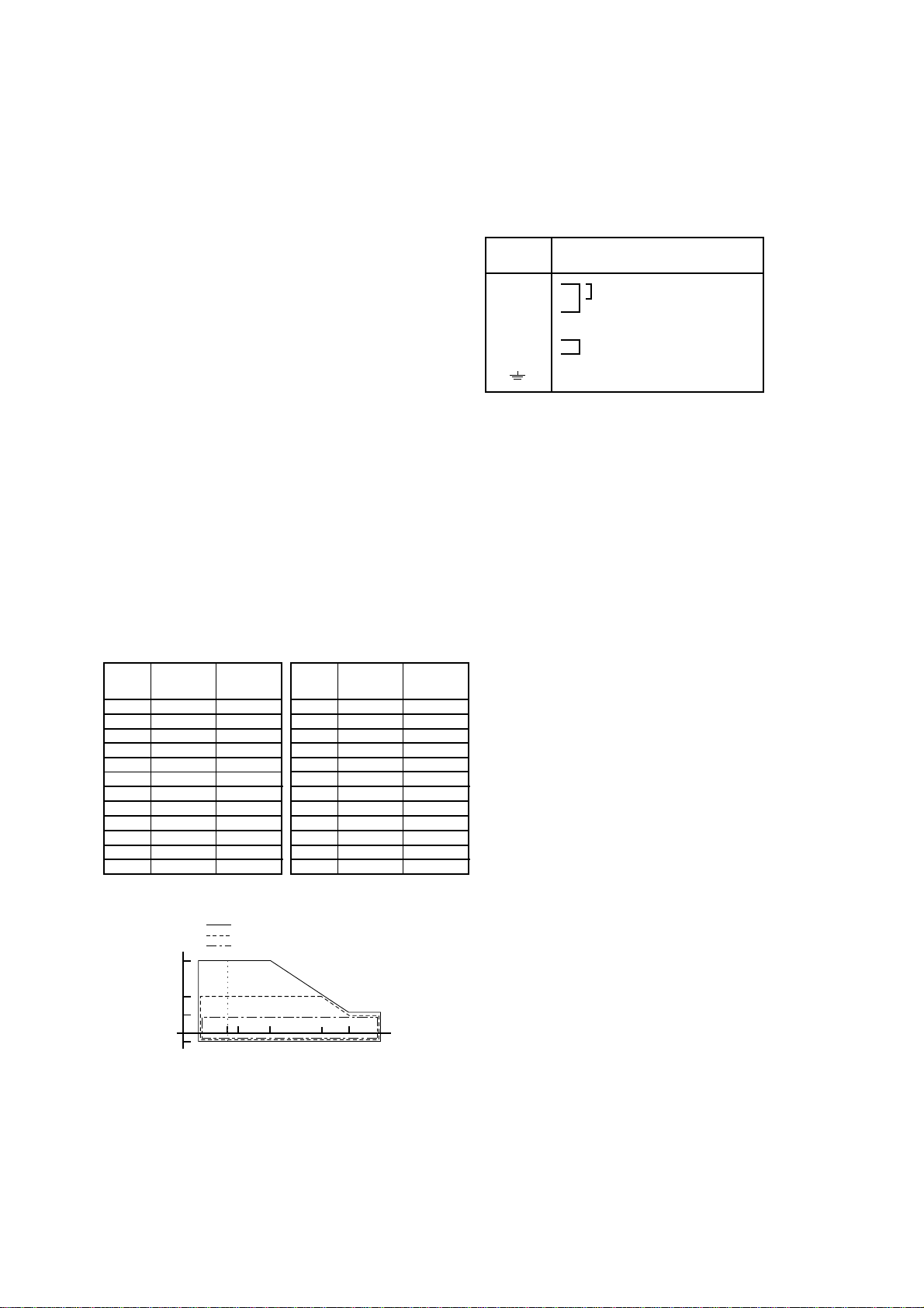
Fluid Temperature and Pressure :
Temperature °C (°F)
Pressure
MPa{kgf/cm
2
}[psi] Size 15mm (0.5in.) to 50mm (2in.)
Size 80mm (3in.) to 300mm (12in.)
Size 350mm (14in.) and 400mm (16in.)
4{40}[570]
2{20}[285]
1{10}[142]
-0.1{-1}[-14.2] -40
(-40) 0
(32)
-10
(14) 100
(212)
40
(104) 130
(266) 160
(320)
F02.EPS
Note 1: This limits show maximum allowable fluid pressure
for FlowTube itself.Further fluid pressure should
also be limitted according to flange rating.
Note 2 : The minimum temperature is -10 °C (14°F) in case
of the 40 mm or larger sizes with the carbon steel
flange connection or wafer connection.
■ACCESSORIES
Centering device 1 set (in case of wafer type)
Hexagonal wrench
(for special screw of Terminal cover) 1
■TERMINAL CONNECTION
Terminal
Symbols Description
A
B
C
EX1
EX2
Common
Excitation current input
Function grounding (Outside of
the Terminal box)
Flow signal output
T04.EPS
This manual suits for next models
2
Table of contents
Other Admag Measuring Instrument manuals


Popular Measuring Instrument manuals by other brands

Endress+Hauser
Endress+Hauser Levelflex M Brief operating instructions

Klein Tools
Klein Tools RT390 instruction manual

Honeywell
Honeywell TS34C user manual

Veeder-Root
Veeder-Root DIS-51 Installation, Setup & Operation Guide

Pitney Bowes
Pitney Bowes DM100i Series Return Instructions

Vitrek
Vitrek XiTRON XT560 user guide


