Overhaul
Prior to performing any maintenance on
equipment, the following safety precautions
must be observed. Personal injury may
occur.
WARNING
Do not use halogenated hydrocarbon
solvents such as methylene chloride or
,,- trichloroethane in this valve.
Explosion can result when aluminum
and/or zinc-plated parts in valve come
in contact with halogenated
hydrocarbon solvents.
Release all pressure within system
prior to performing any overhaul
procedure.
•Disconnect air supply line from pump
motor.
• Operate control valve to discharge
remaining pressure within system
into appropriate container.
Never point control valve at any portion
of body or another person. Accidental
discharge of pressure and/or material
can result in injury. Read each step of
instructions carefully. Make sure proper
understanding is achieved before
proceeding.
Failure to comply may result in death
or serious injury.
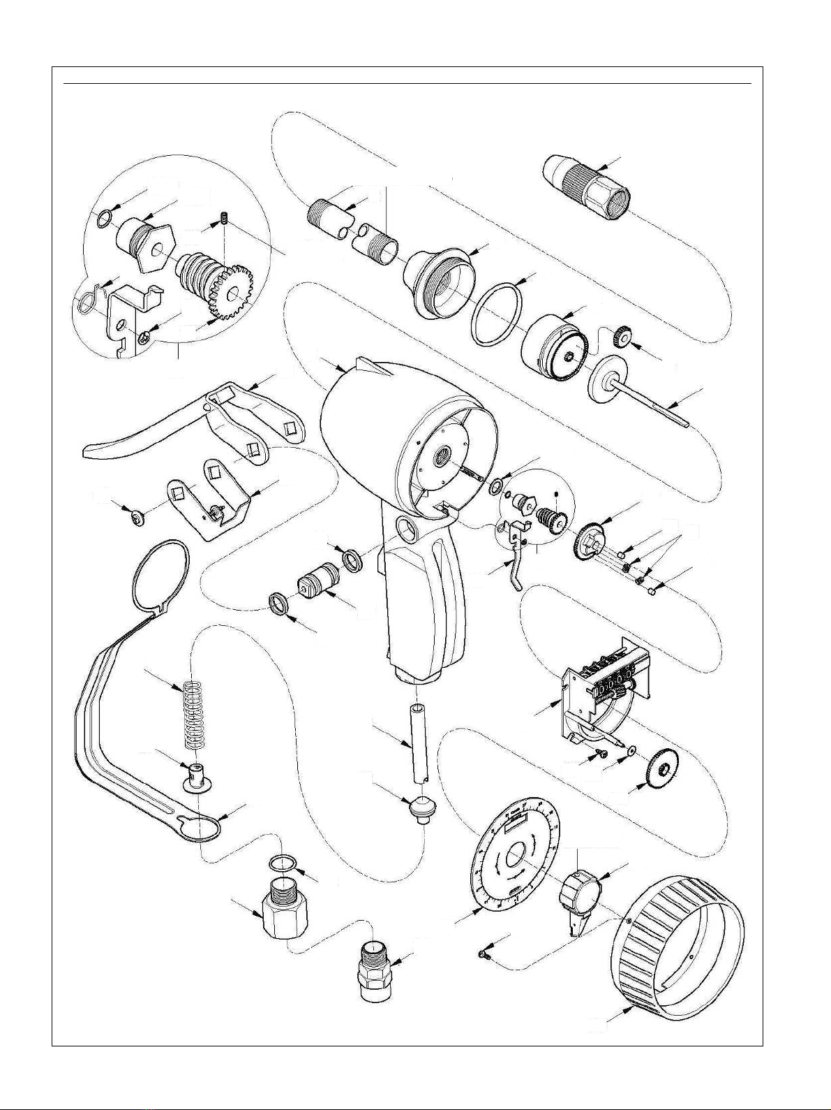
Metering mechanism
assembly
17 Unscrew cap (3) from housing (8).
18 Remove o-ring (4) from cap (3).
19 Remove chamber and pinion assembly (5),
planetary gear (6), and spindle and gear
assembly (7) from housing (8).
20 Remove gland nut (11) from housing (8).
21 Remove o-ring (10) from gland nut (11).
22 Remove washer (9) from housing (8).
Inlet swivel, valve, guard,
and lever assembly
23 Unscrew swivel assembly (35) from
adapter (34).
24 Unscrew adapter (34) from housing (8).
25 Remove hand guard (32) and o-ring (33)
from adapter (34).
26 Remove screen (31), spring (30), valve
assembly (28), and valve sleeve (29)
from housing (8).
27 Remove screws (38) that secure lever
assembly (40) and lock bar and screw
assembly (39) to cam (37).
28 Remove lever assembly (40) and lock bar
and screw assembly from cam (37).
29 Push cam (37) from housing (8).
30 Remove quad rings (36) from cam (37).
Disassembly
NOTE
Refer to Fig. IPB 1, page 10 for
component identification on all overhaul
procedures.
Metered control valve
1 Unscrew extension (2) from cap (3).
2 Unscrew nozzle assembly (1) from
extension (2).
Shroud, pawl, and register
assembly
3 Unscrew screws (26) that secure
shroud (25) to housing (8).
4 Remove shroud (25) from housing (8).
5 Turn pointer (24) counter-clockwise until
access hole in pointer lines up with
setscrew.
6 Loosen setscrew that secures pointer to
spindle and gear assembly (7).
7 Remove dial (27) cam (17), and
pointer (24) as assembly from spindle
and gear assembly (7).
8 Carefully pry pointer (24) from cam
assembly (17) and dial (27) to separate
components.
9 Remove springs (18) and rollers (19)
from cam (17).
10 Remove retaining ring (15) that secures
lock pawl (14) to housing (8).
11 Remove lock pawl (14) and spring (16)
from housing (8).
12 Remove pointer gear (23) and
washer (22) from register assembly (20).
13 Loosen setscrew (12) that secures worm
gear (13) to spindle and gear
assembly (7).
14 Remove worm gear (13) from spindle
and gear assembly (7).
15 Remove screws (21) that secure register
assembly (20) to housing (8).
16 Remove register assembly (20) from
housing (8).