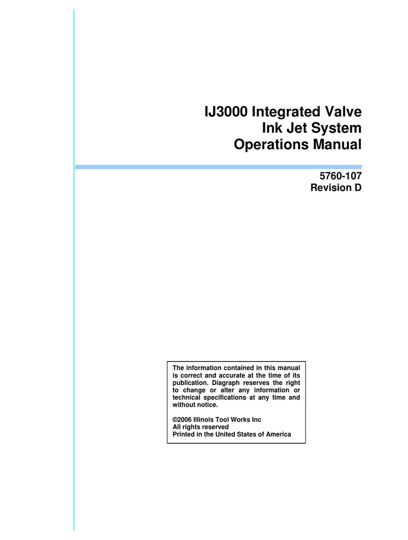
Illinois Tool Works IJ3000 User manual

Operations
Manual
1 Missouri Research Park Drive • St. Charles, MO 63304 • ServiceLine 1-800-526-2531
Illinois Tool Works Inc © 2008
5760-107
Revision G
Integrated Valve
Ink Jet System


The information contained in this manual
is correct and accurate at the time of its
publication. Diagraph reserves the right
to change or alter any information or
technical specifications at any time and
without notice.
©2008 Illinois Tool Works Inc
All rights reserved
Printed in the United States of America
IJ3000 Integrated Valve
Ink Jet System
Operations Manual
5760-107
Revision G


5760-107 Operations Manual Rev G
The IJ3000 system, including all components unless otherwise specified, carries a
limited warranty.
The inks and conditioners used with the IJ3000 system carry a limited warranty.
For all warranty terms and conditions, contact Diagraph an ITW Company for a
complete copy of the Limited Warranty Statement.
Warranty:


Integrated Valve Section 1: Introduction
5760-107 Operations Manual Rev G Page 1 of 106
Section 1: Introduction
This manual covers the installation, operation, and maintenance of the IJ3000 Integrated
Valve (I.V.) Ink Jet Printing System. Also included is a troubleshooting section, parts list
and glossary. The IJ3000 Controller operation is described in a separate manual: 5760-121
IJ3000 Controller Operations Manual.
Your Diagraph IJ3000 Ink Jet System consists of:
•IJ3000 Controller - An ink jet controller with color display, touch screen, and full size
QWERTY keyboard designed to work with Diagraph I.V. (Integrated Valve) print heads
and the IDS3000 Ink Delivery System. (See the IJ3000 Controller Manual, part number
5760-121.)
•I.V. Print Heads - Print Heads designed for high-speed printing applications in harsh
environments using Diagraph porous and non-porous inks.
•IDS3000 - An ink delivery system capable of supplying porous and non-porous ink to a
maximum of eight (8) IV18 Dot or sixteen (16) IV9 Dot Print Heads.
IJ3000 systems range from a single stand-alone print station to multiple print stations
linked together via Ethernet and controlled by a computer. Each print station can control
one or two print head daisy chains, with each daisy chain being any combination of IV9 Dot
and IV18 Dot print heads totaling 72 dots.
Scanned sample of ink jet printing.

Integrated Valve Section 1: Introduction
Page 2 of 106 5760-107 Operations Manual Rev G

Integrated Valve Section 2: Safety
5760-107 Operations Manual Rev G Page 3 of 106
Section 2: Safety
Following is a list of safety symbols and their meanings, which you will find throughout this
manual. Pay attention to these symbols where they appear in the manual.
Wear safety goggles when performing the procedure described!
Caution or Warning! Denotes possible personal injury and/or damage to the equip-
ment.
Caution or Warning! Denotes possible personal injury and/or equipment damage
due to electrical hazard.
NOTE: (Will be followed by a brief comment or explanation.)
Only Diagraph trained personnel should operate and service the equipment.
CAUTION: The IDS3000 Ink Delivery System contains hazardous voltage (115/230VAC).
Turn off the equipment's main power before:
• Performing preventive maintenance.
• Performing any repairs to the unit.
• Servicing the equipment in any manner.
ESD protection should be worn when servicing internal printed circuit boards.
After service to the equipment is completed, replace all protective devices such as ground-
ing cables and covers before operating equipment.
WARNING: This equipment contains ink under pressure. Be sure to depressurize the sys-
tem before servicing.
TSO ink contains ethanol and isopropanol. MEK ink contains methyl ethyl keytone. TWP
ink contains ethylene glycol. It is extremely important to:
• Clean up all spills with the appropriate conditioners immediately and dispose of all
waste according to local and state regulations.
• Wear safety glasses and protective clothing, including gloves, when handling all inks
and conditioners.
• Store inks and conditioners under the recommended conditions found on the MSDS
(Material Safety Data Sheet).
• TWP (Porous Ink) and TSO (Non-Porous Ink) are not miscible.
!
!
!

Integrated Valve Section 2: Safety
Page 4 of 106 5760-107 Operations Manual Rev G

Integrated Valve Section 3: System Components
5760-107 Operations Manual Rev G Page 5 of 106
Section 3: System Components
26
17
24
24 24
16
3 3
3
3
45
7
8
10
15
2
14
12
13
11
18
19
22
23
25
24
20
21
21
27
17
17 17
66
6
6
1
9
IJ3000-ES IJ3000-LS
15 Ink out to Print Heads
16 Ink Supply Tubing
17 Ink Regulator
18 Encoder Cable
19 Photosensor Cable
20 Controller to Print Head
Cable
21 Print Head to Print Head
Cable
22 Ink Filter
23 Throw Distance
24 Ink T Fitting Kit
25 Male Quick Disconnect Kit
26 Ink Supply Cap Assembly
27 Ethernet Cable
1 IJ3000 Controller
2 IDS3000
3 Print Heads
4 Conveyor
5 Product
6 Print Head Bracketry
7 Ink Status Beacon
8 Encoder
9 Ink Supply Container
10 Photosensor
11 Ink Level Detect
12 Power Cord
13 Ethernet Connection
14 Beacon Cable

Integrated Valve Section 3: System Components
Page 6 of 106 5760-107 Operations Manual Rev G
System and Component Part Numbers
The Diagraph IJ3000 Ink Jet System is available with the following components, options
and service kits:
Part Number Description
IJ3000-XLS Controller Assemblies
5760-009SV1D Stainless Enclosure, Single Interface, Domestic
5760-009SV2D Stainless Enclosure, Dual Interface, Domestic
5760-009SV1E Stainless Enclosure, Single Interface, European
5760-009SV2E Stainless Enclosure, Dual Interface, European
IJ3000-ES Controller Assemblies
5765-001DV Painted Enclosure, Single IV Interface, Domestic
5765-001EV Painted Enclosure, Single IV Interface, European
IDS3000 Ink Delivery Assemblies
5760-012SDP Stainless Enclosure, Domestic, Porous
5760-012SDN Stainless Enclosure, Domestic, Non-Porous
IDS3000-ES Ink Delivery Assemblies
5770-005PDP Painted Enclosure, Domestic, Porous
5770-005PDN Painted Enclosure, Domestic, Non-Porous
P.I.C. Ink Delivery Assemblies
5770-004P P.I.C. (Pressurized Ink Can), Porous
5770-004NP P.I.C. (Pressurized Ink Can), Non-Porous
Standard Integrated Valve (I.V.) Print Heads
5770-002P500 1/2”, IV9 Dot, Porous
5770-002N500 1/2”, IV9 Dot, Non-Porous
5770-002P875 7/8”, IV9 Dot, Porous
5770-002N875 7/8”, IV9 Dot, Non-Porous
5770-003P1000 1", IV18 Dot, Porous
5770-003N1000 1", IV18 Dot, Non-Porous
5770-003P2000 2", IV18 Dot, Porous
5770-003N2000 2", IV18 Dot, Non-Porous

Integrated Valve Section 3: System Components
5760-107 Operations Manual Rev G Page 7 of 106
Part Number Description
Print Head Bracketry
2464-561 X-Y Linear Adjustment Bracket Kit, Tool-Less
5760-354 Multi Print Head Conveyor Mounting Kit (Requires Sin-
gle Print Head Kits)
5760-355 Print Head Floor Mounting Kit (Requires Single Print
Head Kits)
5760-356 Multi Print Head Floor Mounting Kit w/24" Bar
(Requires Single Print Head Kits)
5760-357 Multi Print Head Floor Mounting Kit w/44” Bar
(Requires Single Print Head Kits)
5760-365 Linear Adjustment Bracket Kit, Single Axis, Tool-Less
5760-821 Single Print Head Conveyor Mounting Kit, IV9 Dot and
IV18 Dot
Controller/IDS Bracketry
5760-350 Controller/IDS Conveyor Mounting Kit
5760-351 Controller/IDS Pedestal Mounting Kit
5760-352 Controller/IDS T-Base Mounting Kit
5760-362 Controller 90° Pivot Bracket Kit
5765-200 IJ3000-ES Conveyor Mounting Kit
Print Head Cables (when using IDS3000)
5700-245-002 Print Head Cable Assembly, 2’
5700-245-010 Print Head Cable Assembly, 10’
5700-245-025 Print Head Cable Assembly, 25’
Print Head Cables (when using P.I.C. IDS)
5765-311-010 Print Head Extension Cable, DB15, 10’
5765-311-025 Print Head Extension Cable, DB15, 25’
(Also see page 12)
(Also see page 11)

Integrated Valve Section 3: System Components
Page 8 of 106 5760-107 Operations Manual Rev G
Part Number Description
Encoder and Photosensor
5760-820-IJ Encoder Assembly w/Mounting Bracket & 25’ Cable
5760-383 Photosensor, Diffuse Type & 20’ Cable
2464182-010 Encoder or Photosensor Extension Cable, 10’
2464182-025 Encoder or Photosensor Extension Cable, 25’
Ink Cap Assemblies and Plumbing
5760-307 5 Gallon Ink Cap Assembly
5760-309 30 Gallon Ink Cap Assembly
5760-310 Inlet Tubing and Filters

Integrated Valve Section 3: System Components
5760-107 Operations Manual Rev G Page 9 of 106
IJ3000 Controller
The controller gathers and stores all the information required for
printing a message. This information can come from the follow-
ing sources:
1. The user interface, which tells the controller what message
to print on the product.
2. The photosensor, which tells the controller when to print.
3. The encoder, which tells the controller how fast to print.
There are two types of encoders:
•A built-in fixed speed encoder is used when the con-
veyor speed does not change.
•An optional, conveyor-mounted variable speed encoder is used when the line speed
varies or has frequent starts and stops.
With this information, the controller knows exactly when the leading edge of the product will
reach the print head and at what rate of speed.
The controller comes in a stainless steel or painted metal case that makes it splash-proof
and resistant to electromagnetic interference. A hinged cover provides access to replace-
able parts.
The IJ3000 Integrated Valve Controller can control any combination of IV9 Dot and IV18
Dot print heads totaling 72 dots per interface board.
IDS3000 Ink Delivery System
The Ink Delivery System (IDS) provides ink to the
print heads. The IDS contains an Ink Pump, Accumu-
lator, and printed Circuit Board to control ink supply to
the print heads. Ink is pumped into an internal accu-
mulator to supply constant ink pressure to the print
heads.
The IDS includes system connectivity to supply oper-
ational data including Ink Low, Ink Out, and Broken
Line safety information. See “IDS3000 Ink Delivery
System Features” on page 66 for a complete opera-
tional description.
IDS3000
Power
Prime

Integrated Valve Section 3: System Components
Page 10 of 106 5760-107 Operations Manual Rev G
IDS3000-ES Ink Delivery System
The IDS3000-ES Ink Delivery System provides pres-
surized ink to the integrated valve print heads. The sys-
tem contains an ink pump, fluid capacitor and printed
circuit board to control ink supply to the print heads. Ink
is pumped into the fluid capacitor to provide a constant
ink pressure source.
The IDS3000-ES provides connectivity to the float
switch in the ink supply tank and a beacon to communi-
cate ink status. See “IDS3000 Ink Delivery System
Features” on page 66 for a complete operational
description.
P.I.C. IDS
The Pressurized Ink Can Ink Delivery System (P.I.C. IDS) provides ink to
the print heads. The P.I.C. IDS regulates the pressure from a can of ink
down to 15 psi to provide a constant ink pressure at the print heads.
Ink low is detected from the pressure sensor internal to the print head. A
signal is sent from the print head back to the controller warning that the
can of ink needs to be replaced.
NOTE: Print head cables 5765-311-010 and/or 5765-311-025 must be
used in conjunction with a P.I.C. IDS. The standard print head cables do
not have enough conductors to carry the ink low signal from the print head
back to the controller.
POWER
SWITCH
INKOUTBEACON
POWER CORD

Integrated Valve Section 3: System Components
5760-107 Operations Manual Rev G Page 11 of 106
Bracketry
Controller/IDS Bracketry
Bracketry is the structure that supports the controller, IDS, print heads, and other accesso-
ries. This manual details instructions for mounting all system components to a conveyor.
Other mounting options for the controller and IDS include the T-stand and pedestal mount,
shown below. Assembly instructions are included with parts kits.
T-STAND
PEDESTAL
MOUNT
T-STAND
5765-200
IJ3000-ES
IDS3000-ES
CONVEYOR
MOUNT

Integrated Valve Section 3: System Components
Page 12 of 106 5760-107 Operations Manual Rev G
Print Head Bracketry
There are numerous options for mounting print heads. Diagraph bracketry is modular and
can assume several configurations:
• Single-pole conveyor mount
• Double-pole conveyor mount
• Single-pole floor mount
• Double-pole floor mount
• Multi-panel floor mount
SINGLE POLE
FLOOR MOUNT
IV PRINTHEAD 5760-821
5760-354
IV PRINTHEAD
5760-821
SINGLE POLE
CONVEYOR MOUNT
DOUBLE POLE
CONVEYOR MOUNT

Integrated Valve Section 3: System Components
5760-107 Operations Manual Rev G Page 13 of 106
MULTI-PANEL
FLOOR MOUNT
DOUBLE POLE
FLOOR MOUNT

Integrated Valve Section 3: System Components
Page 14 of 106 5760-107 Operations Manual Rev G
Print Heads
The Diagraph Integrated Valve (I.V.) print
head uses a flexible membrane sand-
wiched between two plates, which pro-
pels ink droplets onto moving surfaces
by solenoid activation.
This design keeps the ink between the
front-plate and membrane, away from
the solenoids.
The I.V. print head is capable of printing
at very high line speeds with a minimum
of required maintenance. It can produce
highly legible ¼" to 2" tall alphanumerics,
special characters and logos.
Each type of I.V. print head has specific distances above and below the orifices, spaces in
which the print head cannot print. These non-printing zones are critical when designing
print head layout in multi-head applications. The figure below shows the print and non-print
areas obtained when two IV9 Dot print heads are stacked on a vertical bracket, as in the
"Single Pole Floor Mount" illustration on a previous page. See the table on the next page
for specific non-printing zones for each print head model.
C C
B
PRINTING ZONE
A
B
A
PRINTING ZONE
Other manuals for IJ3000
1
Table of contents
Other Illinois Tool Works Control Unit manuals
Popular Control Unit manuals by other brands

Honeywell
Honeywell 7800 SERIES installation instructions

herdstar
herdstar BinTrac Breeder Control Operation manual
spartan scientific
spartan scientific CRDV/S Application and installation guide

tedee
tedee BleBox smart installation manual
jbc
jbc MVE-A instruction manual
National Instruments
National Instruments PXIe-8830mc user manual
Lenze
Lenze EMF2133IB Communications manual

Whelen Engineering Company
Whelen Engineering Company E-2010 Operation & installation manual

ITT
ITT Flygt 4901 Installation, Care and Maintenance

Texas Instruments
Texas Instruments AM437x user guide
JED
JED JED T440 user manual
Basler
Basler MVC 236 Instructional manual
