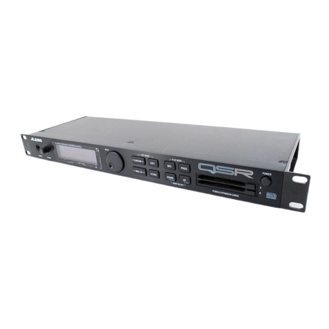
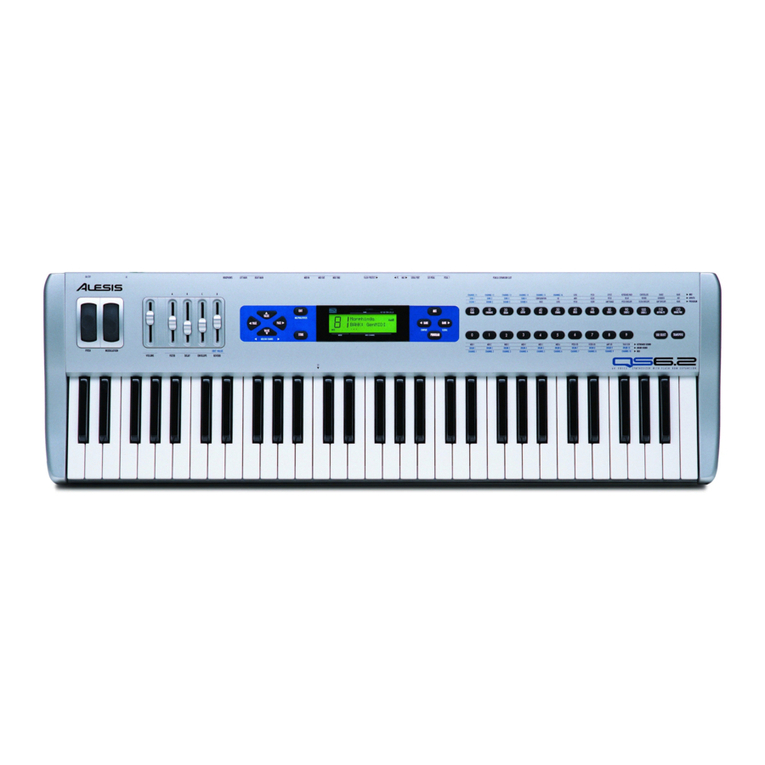
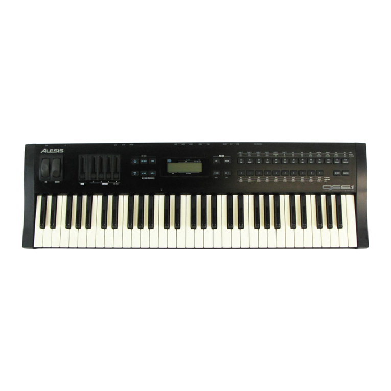
Alesis QS Series User manual


Alesis QS Series Keyboards Service Manual V1.00 ii 11/19/06
Preface
This document is intended to assist the service technician in the operation, maintenance
and repair of the QS Series 64 Voice Synthesizer/Controller Keyboards. Together with the User
Reference Manuals, this document provides a complete description of the functionality and
serviceability of the QS Series. Any comments or suggestions you may have pertaining to the
document are welcome and encouraged.
READ THIS!
In addition to any purchase price that Alesis may charge as consideration for Alesis
selling or otherwise transferring this service manual (“Manual”) to you, if you are not a
service and repair facility (“Service Center”) authorized by Alesis in writing to be an
authorized Service Center, Alesis sells or transfers the Manual to you on the following
terms and conditions:
Only Service Centers authorized by Alesis in writing are authorized to perform service and repairs
covered by an Alesis warranty (if any), and transfer of the Manual to you does not authorize you to
be an authorized Service Center. Therefore, if you perform, or if the Manual is used to
perform, any service or repairs on any Alesis product or part thereof, any and all
warranties of Alesis as to that product and any service contract with Alesis for that
product shall be voided and shall no longer apply for such product, even if your services
or repairs were done in accordance with the Manual.
All service or repairs done by you or with reference to the Manual shall be solely your
responsibility, and Alesis shall have no liability for any such repairs or service work. All such
service or repairs are performed at the sole risk of the person performing the service or
repairs. You agree that all such work will be performed in a competent, professional and safe
manner at all times and to indemnify and fully hold Alesis and its successors and assigns
harmless in the event of any failure to so perform.
Your purchase of the Manual shall be for your own ultimate use and shall not be for purposes of
resale or other transfer.
As the owner of the copyright to the Manual, Alesis does not give you the right to copy the Manual,
and you agree not to copy the Manual without the written authorization of Alesis. Alesis has no
obligation to provide to you any correction of, or supplement to, the Manual, or any new or
superseding version thereof.
Alesis shall have the right to refuse to sell or otherwise transfer repair parts or materials to you in
its sole discretion. You shall not use, sell or otherwise transfer spare or replacement parts
supplied by Alesis to you (i) to repair or be used in products manufactured for or by third parties or
(ii) to any third parties for any purpose.
You shall not make any warranties or guarantees with respect to the products of Alesis or the use
thereof on behalf of Alesis or in your own name.
The foregoing describes the entire understanding related to sale or transfer of the Manual to you,
and no other terms shall apply unless in a writing signed by an authorized representative of Alesis.
All Trademarks are property of their respective companies.

Alesis QS Series Keyboards Service Manual V1.00 iii 11/19/06
Warnings
TO REDUCE THE RISK OF ELECTRIC SHOCK OR FIRE, DO NOT EXPOSE THIS
PRODUCT TO WATER OR MOISTURE.
CAUTION
RISK OF ELECTRIC SHOCK
DO NOT OPEN
The arrowhead symbol on a lightning flash inside a triangle is intended to alert
the user to the presence of un-insulated "dangerous voltage" within the enclosed
product which may be of sufficient magnitude to constitute a risk of electric shock
to persons.
The exclamation point inside a triangle is intended to alert the user to the
presence of important operating, maintenance and servicing instructions in the
literature which accompanies the product.
REPAIR BY ANY PERSON OR ENTITY OTHER THAN AN AUTHORIZED ALESIS SERVICE
CENTER WILL VOID THE ALESIS WARRANTY.
PROVISION OF THIS MANUAL DOES NOT AUTHORIZE THE RECIPIENT TO COMPETE
WITH ANY ALESIS DISTRIBUTOR OR AUTHORIZED REPAIR SERVICE CENTER IN THE
PROVISION OF REPAIR SERVICES OR TO BE OR MAKE REPAIRS AS AN AUTHORIZED
SERVICE CENTER.
ALL REPAIRS DONE BY ANY ENTITY OTHER THAN AN AUTHORIZED ALESIS SERVICE
CENTER SHALL BE SOLELY THE RESPONSIBILITY OF THAT ENTITY, AND ALESIS
SHALL HAVE NO LIABILITY TO THAT ENTITY OR TO ANY OTHER PARTY FOR ANY
REPAIRS BY THAT ENTITY.
CAUTION
Danger of explosion if battery is incorrectly replaced.
Replace only with the same type or equivalent type
recommended by the equipment manufacturer.
Battery Manufacturer: Panasonic/Matsushita
Type: BR2325
Rating 3V, 5mA

Alesis QS Series Keyboards Service Manual V1.00 iv 11/19/06
Safety Suggestions
Carefully read the applicable items of the operating instructions and these safety suggestions
before using this product. Use extra care to follow the warnings written on the product itself and
in the operating instructions. Keep the operating instructions and safety suggestions for
reference in the future.
1. Power Source. The product should only be connected to a power supply which is described either in the
operating instructions or in markings on the product.
2. Power Cord Protection. AC power supply cords should be placed such that no one is likely to step on the
cords and such that nothing will be placed on or against them.
3. Periods of Non-use. If the product is not used for any significant period of time, the product's AC power
supply cord should be unplugged from the AC outlet.
4. Foreign Objects and Liquids. Take care not to allow liquids to spill or objects to fall into any openings of the
product.
5. Water or Moisture. The product should not be used near any water or in moisture.
6. Heat. Do not place the product near heat sources such as stoves, heat registers, radiators or other heat
producing equipment.
7. Ventilation. When installing the product, make sure that the product has adequate ventilation. Improperly
ventilating the product may cause overheating, which may damage the product.
8. Mounting. The product should only be used with a rack which the manufacturer recommends. The
combination of the product and rack should be moved carefully. Quick movements, excessive force or
uneven surfaces may overturn the combination which may damage the product and rack combination.
9. Cleaning. The product should only be cleaned as the manufacturer recommends.
10. Service. The user should only attempt the limited service or upkeep specifically described in the operating
instructions for the user. For any other service required, the product should be taken to an authorized
Service Center as described in the operating instructions.
11. Damage to the Product. Qualified service personnel should service the unit in certain situations including
without limitation when:
a. Liquid has spilled or objects have fallen into the product,
b. The product is exposed to water or excessive moisture,
c. The AC power supply plug or cord is damaged,
d. The product shows an inappropriate change in performance or does not operate normally, or
e. The enclosure of the product has been damaged.

Alesis QS Series Keyboards Service Manual V1.00 v 11/19/06
General Troubleshooting
While this manual assumes that the reader has a fundamental understanding of
electronics and basic troubleshooting techniques, a review of some of the techniques used by
our staff may help.
✰Visual Inspection - A short visual inspection of the unit under test will often yield results
without the need of complex signal analysis (burnt, or loose components are a dead
giveaway).
✰Self Test - Alesis products that utilize microprocessor control contain built in test software
which exercises many of the units' primary circuit functions. Self test should always be done
following any repair to ensure basic functionality.
✰Environmental Testing - Applying heat and cold (heat gun/freeze spray) will often reveal
thermally intermittent components (Clock crystals, I.C.s, and capacitors are particularly
prone to this type of failure).
✰Burn in Testing - Leaving a unit running overnight often reveals intermittent failures such as
capacitors that begin to leak excess current after a significant amount of time.
✰Cable Checks - Wiggling cables can reveal intermittent failures such as loose cables or
poorly soldered headers. Remember to check power supply cables as well.
✰Flexing the PC Board - Poor solder joints and broken traces can often be found by pressing
the PC Board in various places.
✰Tapping Components - Sometimes tapping on a component (particularly crystals) will cause
it to fail.
✰Power Down/up - Turning the unit off and back on rapidly several times may reveal odd
reset and/or power supply failures.
✰Reset Threshold - A Variac (variable transformer) can be used to check reset threshold
levels. This can be particularly useful in helping customers with low line problems.
✰Compressors - Using a compressor/limiter is often helpful when attempting to solve low
level noise problems, as well as assisting with DAC adjustments.
✰Sweep Tests - Sweep generators are very useful in checking the frequency response
envelopes of anti-aliasing filters.
✰Piggybacking - Piggybacking I.C.s is particularly useful when troubleshooting large sections
of logic. This is especially true when working with older units.

Alesis QS Series Keyboards Service Manual V1.00 11/19/06
vi
Acknowledgments
While I get the credit for the whole thing, as with any serious book, there is really a team
effort behind it. So this is my opportunity to thank all of those who’s special efforts help me look
good. Technicians Joe Reyes, Steve McCain, and Ron Dorsey. Their day to day experience
and help with proofreading are an integral part of this effort. Engineers Robert Rampley, and
Mike Murphy for their insight and documentation assistance. Parts gods Chris Martin and
Wayne Hamilton for help in procuring (you guessed it!) parts. My Boss John Sarappo for
having the confidence in me to let me do things my way (as well as having the final
proofreading say). The entire Alesis staff. Let’s face it, without their professionalism and skill,
there wouldn’t be any Alesis products for me to write about.
In addition to the support of my family and thanking the usual crowd of slackers I call my
friends, I’d also like to thank Speedvision network for almost satisfying my insatiable jones for
motorsports. Congratulations to Damon Hill for winning the Formula 1 Championship. I have
developed a great appreciation for how much effort it takes to win championships like that.
Last on the list, but first in class is of course You. Without You, none of this is needed,
and I’m out of a job! Beyond that, You give me the feedback that allows me to continue to
improve both myself, and the current state of the art in service documentation. It is always our
intention to provide You with the best information possible. Tell us what You need, and we’ll try
to get it to You.
T.J. Goodwin
Technical Services Coordinator.

Alesis QS Series Keyboards Service Manual V1.00 11/19/06
vii
Table Of Contents
Preface ................................................................................................................ii
READ THIS!.........................................................................................................ii
Warnings.............................................................................................................iii
Safety Suggestions ............................................................................................iv
General Troubleshooting...................................................................................v
Acknowledgments..............................................................................................vi
Table Of Contents...............................................................................................vii
List Of Figures....................................................................................................ix
List Of Tables......................................................................................................ix
1.00 General Descriptions..................................................................................1
1.10 QS6............................................................................................................1
1.20 QS7............................................................................................................3
1.30 QS8............................................................................................................3
1.40 QSR...........................................................................................................5
2.00 Theory Of Operation...................................................................................7
2.10 Power Supplies..........................................................................................7
2.11 QS6/QSR Power Supply ......................................................................... 7
2.12 QS7/QS8 Power Supply.......................................................................... 7
2.12A Transformer PCB..................................................................................7
2.12B Main PCB..............................................................................................7
2.13 SRAM Battery Backup.............................................................................7
2.20 Analog Signal Paths...................................................................................7
2.21 Main Outputs........................................................................................... 7
2.22 Headphone Outputs................................................................................ 8
2.23 QS7/QS8/QSR Aux Outputs.................................................................... 8
2.24 Power Up Mute........................................................................................ 8
2.30 Digital Signal Paths....................................................................................8
2.31 H8/510 Microprocessor...........................................................................8
2.31A RESET..................................................................................................9
2.31B The GAL and Memory Mapped I/O .......................................................10
2.31C Other Processor I/O..............................................................................10
2.31D MIDI......................................................................................................10
2.31E PC Serial Connector .............................................................................11
2.32 The SG ASIC........................................................................................... 11
2.32A Sound Generation.................................................................................11
2.32B ROM Card Connector ...........................................................................12
2.33 The FX ASIC ...........................................................................................12
2.33A QS7/8/R Digital Optical I/O...................................................................12
2.34 The KEYSCAN ASIC...............................................................................12
2.34A Reading Velocity...................................................................................13
2.34B QS8 Key Construction...........................................................................13
2.40 D-A.............................................................................................................16
2.41 S6 D-A..................................................................................................... 16
2.42 QS7/QS8/QSR D-A.................................................................................17
2.50 PC/MAC Serial I/O.....................................................................................17
2.51 QS Serial Input........................................................................................ 18
2.52 QS Serial Output..................................................................................... 18
2.53 PC/MAC Switch.......................................................................................18
2.53A QS6/7/8 PC Serial.................................................................................19
2.53B QS6/7/8 MAC Serial..............................................................................19
2.53C QSR Variant .........................................................................................19
2.54 H8 UART Clocking..................................................................................19
3.00 Test Procedures..........................................................................................20
3.10 Self Tests...................................................................................................20
3.11 Automated Test Mode.............................................................................20
3.12 Individual Test Mode............................................................................... 20
3.13 Differences In QSR Self Tests ................................................................ 21

Alesis QS Series Keyboards Service Manual V1.00 11/19/06
viii
3.20 Further Testing ..........................................................................................22
3.21 Testing 48KHz......................................................................................... 22
4.00 Troubleshooting and Repair......................................................................23
4.10 QS6/QS7/QS8 Disassembly/Reassembly.................................................23
4.20 QSR Disassembly/Reassembly.................................................................25
4.30 Replacing A Whole Keyboard....................................................................25
4.40 Replacing Individual Keys..........................................................................25
4.51 Replacing QS6 And QS7 Keys................................................................ 26
4.52 Replacing QS8 Keys............................................................................... 26
4.60 General Troubleshooting...........................................................................27
5.00 Appendix A Pinout Diagrams.....................................................................28
5.10 SG ASIC..................................................................................................28
5.11 FX ASIC .................................................................................................. 28
5.12 KEYSCAN ASIC...................................................................................... 29
5.13 MICRO CONTROLLER...........................................................................29
5.14 SRAM...................................................................................................... 30
5.15 EPROM................................................................................................... 30
5.16 SOUND ROM..........................................................................................30
5.19 GAL.........................................................................................................31
5.20 DAC......................................................................................................... 31
6.00 Appendix A Updates And Corrections ......................................................32
6.10 QS6............................................................................................................32
6.11 QS6 Main Revision B..............................................................................32
6.12 QS6 Main Revision C.............................................................................. 33
6.13 QS6 Main Revision D.............................................................................. 33
6.14 QS6 Main Revision E..............................................................................33
6.15 QS6 Main Revision F ..............................................................................34
6.20 QS7/8.........................................................................................................35
6.21 QS7/8 Main Revision B...........................................................................35
6.22 QS7/8 Main Revision C........................................................................... 36
6.23 QS7/8 Main Revision D........................................................................... 36
6.24 QS7/8 Main Revision E...........................................................................37
6.25 QS7/8 Main Revision F ...........................................................................37
6.25 Changes To QS7/QS8 VCO Circuit (All Main PCB Revisions)................ 38
6.30 QSR...........................................................................................................38
7.00 Appendix B Software Histories .................................................................39
7.10 QS6............................................................................................................39
7.20 QS7/QS8 ...................................................................................................40
7.40 QSR...........................................................................................................40
8.00 Appendix C Sys-Ex Implementations........................................................42
8.10 S6 Sys-Ex..................................................................................................42
8.20 QS7/QS8//QSR Sys-Ex .............................................................................67
9.00 Appendix D Service Parts Lists.................................................................68
9.10 QS6 Service Parts List...............................................................................68
9.20 QS7 Service Parts List...............................................................................72
9.30 QSR Service Parts List..............................................................................76
9.40 QS8 Service Parts List...............................................................................79
10.00 Appendix E Dictionary Of Selected Terms..............................................83
11.00 INDEX ........................................................................................................85
12.00 Schematics................................................................................................88

Alesis QS Series Keyboards Service Manual V1.00 11/19/06
ix
List Of Figures
Figure 1 - QS6 Simplified Block Diagram......................................................................................2
Figure 2 - QS7/QS8 Simplified Block Diagram..............................................................................4
Figure 3 - QSR Simplified Block Diagram .....................................................................................6
Figure 4 - Keyboard Velocity Reponse........................................................................................13
Figure 5 - QS8 Key Construction.................................................................................................15
Figure 6 - Alesis Serial Port Pinout..............................................................................................17
Figure 7 - Examples of Switch Self Test Key Press Order..........................................................21
Figure 8 - 48KHz Test .................................................................................................................22
Figure 9 - Keyboard Casetop Removal.......................................................................................23
Figure 10 - S6 Case Screw Locations.........................................................................................24
Figure 11 - QS7QS8 Case Screw Locations...............................................................................24
Figure 12 - QSR Case Screw Locations......................................................................................25
Figure 13 - QS6 Key Release Location.......................................................................................26
Figure 14 - Key Release Catch Location.....................................................................................26
Figure 15 - SG ASIC Pinout ........................................................................................................28
Figure 16 - FX ASIC Pinout.........................................................................................................28
Figure 17 - Keyscan ASIC Pinout................................................................................................29
Figure 18 - H8 Processor Pinout.................................................................................................29
Figure 19 - FX SRAM Pinout.......................................................................................................30
Figure 20 - EPROM Pinout..........................................................................................................30
Figure 21- Sound ROM Pinout....................................................................................................30
Figure 22 - GAL Pinout................................................................................................................31
Figure 23 - DAC Pinout ...............................................................................................................31
List Of Tables
Table 1 - Pin to Pin Connections for 9 Pin PC Serial to QS........................................................ 17
Table 2 - Pin to Pin Connections for 25 Pin PC Serial to QS...................................................... 18
Table 3 - Pin to Pin Connections for MAC Serial to QS .............................................................. 18
Table 4 - QS6 Main PCB Revision B Changes ........................................................................... 32
Table 5 - QS6 Main PCB Revision C Changes........................................................................... 33
Table 6 - QS6 Main PCB Revision D Changes........................................................................... 33
Table 7 - QS6 Main PCB Revision E Changes ........................................................................... 33
Table 8 - QS6 Main PCB Revision F Changes............................................................................ 34
Table 9 - QS7/8 Main PCB Revision B Changes ........................................................................ 35
Table 10 - QS7/8 Main PCB Revision C Changes...................................................................... 36
Table 11 - QS7/8 Main PCB Revision D Changes...................................................................... 36
Table 12 - QS7/8 Main PCB Revision E Changes ...................................................................... 37
Table 13 - QS7/8 Main PCB Revision F Changes....................................................................... 37
Table 14 - Schematic Set............................................................................................................ 88

Alesis QS Series Keyboards Service Manual V1.00 11/19/06
1
1.00 General Descriptions
The QS series of 64 voice, keyboard and rack mount digital synthesizers represent the
current state of the art in high end digital synthesizers. It is certainly recommended that
technicians be thoroughly familiar with the operation of the units according to the User’s
Reference Manuals before attempting any repair. As is often the case when machines present
the user with so many options, many “repairs” can be made simply through education in the
correct way to use the product. The software histories in Appendix B of this manual may also
prove to be an excellent aid in troubleshooting User difficulties.
Several of these units utilize the same PCBs. For example, the QS7 and QS8 have
identical main PCBs, and all three keyboards (QS6, QS7, and QS8) use the same keypad
PCB. However, some PCBs may be different between individual units while performing similar
functions. In order to minimize confusion between reference designators for the different unit
types, the following conventions will be used throughout this manual:
➫ QS6 Reference Designators are BOLD (e.g. R6, C9)
➫ QS7 Reference Designators are Italicized (e.g. R6, C9)
➫ QS8 Reference Designators are Underlined (e.g. R6, C9)
➫ QSR Reference Designators are Plain (e.g. R6, C9)
➫ Combinations are allowed (i.e. Italicized and underlined indicate both
QS7 and QS8 references) (e.g. R6, C9)
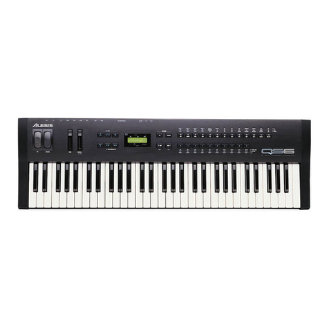
1.10 QS6
With the release of the original S5 (later updated to S5+ A.K.A. S9) QuadraSynth
keyboard and the S4 (later S4+ or S8), Alesis jumped to the forefront of a field in which it had
no previous experience. Since then, we have learned a great deal about the construction of
keyboards, as well as the needs of keyboard players in general. This inevitably led to the
release of the QS6. Smaller, lighter, and with improved sound quality, the QS6 was an instant
success. Still minor improvements have been made through the lifetime of this which have
resulted in several main PCB revisions. Each revision incorporates previous changes as well
as any new improvements made. These changes are outlined in Appendix A. This manual
references the following schematics and component I.D.s unless otherwise noted:
PCB Schematic Revision
Main S6 B
Slider S6 B
Keypad QS6/7/8 C
Refer to Figure 1 for a simplified view of the QS6’s electronic systems.

Alesis QS Series Keyboards Service Manual V1.00 11/19/06
2
Figure 1 - QS6 Simplified Block Diagram

Alesis QS Series Keyboards Service Manual V1.00 11/19/06
3
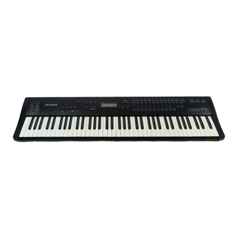
1.20 QS7
The QS7 further expanded and improved the system used in the QS6. The larger QS7
is heavier and therefore less portable, but it’s expanded keyboard enhances it’s use as a
master keyboard controller for the studio. Refer to Figure 2 for a simplified view of the QS7’s
electronic systems. Note that the QS7 is electrically similar to the QS8 (same Main and
Xformer PCBs) and only vary in the number of keys used.
PCB Schematic Revision
Main QS7/QS8 F
Slider QS7/QS8 A
Keypad QS6/7/8 C
XFormer QS7/QS8 C
1.30 QS8
In listening to the needs of keyboard players around the world, what came up
consistently was our need to improve the keys themselves. While the weighted keys of
previous units would suffice for most purposes, many high end players still preferred the “feel”
of real piano keys. In answer to this need, Alesis designed the QS8 88 key, piano weighted
keyboard. The keys were specifically designed to simulate the same “feel” that acoustic piano
keys have when the hammer strikes the piano strings. Incorporating the same basic sound
engine as it’s predecessors, the QS8 is sure to rank highly among players and composers
alike. (Minor improvements have be made through the lifetime of this product. This has
resulted in several main PCB revisions. Each revision incorporates previous changes as well
as any new improvements made. These changes are outlined in Appendix A. This manual
references the following schematics and component I.D.s unless otherwise noted: Refer to
Figure 2 for a simplified view of the QS8’s electronic systems.)
PCB Schematic Revision
Main QS7/QS8 F
Slider QS7/QS8 A
Keypad QS6/7/8 C
XFormer QS7/QS8 C

Alesis QS Series Keyboards Service Manual V1.00 4 11/19/06
Figure 2 - QS7/QS8 Simplified Block Diagram

Alesis QS Series Keyboards Service Manual V1.00 11/19/06
5
1.40 QSR
Many current keyboard players already have their favorite controller keyboard, but still
desire the great sound provided by the Alesis QS Series. Since multiple keyboards can take up
excessive space, the obvious solution is a rack mount sound engine without keys. The QSR is
just that solution. Whether used for the road or in the studio, the QSR is a powerful addition to
any MIDI setup. Minor improvements have been made through the pre production lifetime of
this product. This has resulted in several main PCB revisions. Each one incorporates previous
changes as well as any new improvements made. These changes are outlined in Appendix A.
This manual references the following schematics and component I.D.s unless otherwise noted:
PCB Schematic Revision
Main A
Front Panel X2

Alesis QS Series Keyboards Service Manual V1.00 11/19/06
6
Figure 3 - QSR Simplified Block Diagram

Alesis QS Series Keyboards Service Manual V1.00 11/19/06
7
2.00 Theory Of Operation
2.10 Power Supplies
2.11 QS6/QSR Power Supply
The power supply begins with the Alesis P4 type transformer input at J1 J15. After the
power switch (SW2 S1), the signal is rectified (D1, D2 D12 D11), input filtered (C3, C9 and C25
C86, C80 and C81), regulated (U9, U10 U31, U32), and finally output filtered (C24, C32 and
C35, C34 C77, C78 and C82, C83) into the +5V and -5V supplies needed by the unit. In
addition, many 0.1µF capacitors are located throughout the system to act as supply filters. Note
that the +5V rail requires a lot more filtering due to the digital supply needs.
2.12 QS7/QS8 Power Supply
2.12A Transformer PCB
Input from R.F.I. filter enters the Transformer PCB via J1. The current is fused (F1)
prior to the primary of the ECO 4 Transformer (X1). Note that the transformers of countries
outside the United States are varied according to the power grid requirements for that country.
Output from the transformer PCB is routed to the main PCB via J2.
2.12B Main PCB
Transformer output is bridge rectified (D1, D2, D4 , and D5), input filtered (C8, C96, and
C15), regulated (U6, U4), and finally output filtered (C38, C34, C18, and C24) into the +5V and
-5V supplies needed by the unit. In addition, many 0.1µF capacitors are located throughout the
system to act as supply filters. Note that the +5V rail requires a lot more filtering due to the
digital supply needs.
2.13 SRAM Battery Backup
The user storage/system SRAM requires a small standby supply current while it is
normally powered down. The battery current is supplied via a transistor circuit (Q7 Q4 Q4)
designed prevent the +5V rail from trying to charge the battery, while ensuring that a solid +5V
is supplied to the SRAM during normal operation.
2.20 Analog Signal Paths
Since these units are largely digital in nature, analog signals are limited to two major
types:
☞ Audio Signal Output
☞ Slider and Aftertouch strain gauge input
2.21 Main Outputs
Differential analog output from the DAC is anti-alias filtered and buffered by U6A U3A
U3A (left) and U6B U3B U3B (Right). This signal is sent to the stereo output level slidepot R1
R2 via J11 J4 J1.

Alesis QS Series Keyboards Service Manual V1.00 11/19/06
8
2.22 Headphone Outputs
The signal from the volume slider is sent through a X10 X3 X3 gain stage U5A, U5B
U2A, U2B U1B, U1A, current limited R12, R13 R3, R2 R1, R2 and output through the stereo
jack J2 J1 J1.
2.23 QS7/QS8/QSR Aux Outputs
The Aux outputs are completely isolated from the main outputs by virtue of a separate
DAC U3 U4. The differential output of the DAC is anti-alias filtered and buffered by U3C U3C
(left) and U3D U3D (right). This signal is current limited (R31, R32 R31, R32), R.F. Filtered
(C35, C36 C33, C34), and output via the ¼ “ jacks (J8, J9 J5, J4).
2.24 Power Up Mute
The Power Up (PUP) mute circuit ensures that no sound is output during the critical
stages of powering the unit up and down. Most often noise is created due to the uneven power
demands placed on the positive and negative rails, especially at power up. There also may be
noise due to the random power up states in the digital hardware prior to the software
establishing correct values. Muting is accomplished with the use of the microprocessor reset
line (See Section 2.31A).
The positive and negative supplies are fed to the final analog output stages via
transistors Q2, Q4 Q1,Q3 Q1, Q3. R48, R50 and R51 R13, R18 and R19 R13, R18 and R19
are used to bias these transistors into saturation when the circuit is switched on. Q3 Q2 Q2
provides the necessary current to switch the supply transistors on, as well as providing a
threshold value for timing purposes. Since power up noise may extend past the time necessary
for the digital hardware to physically reset, a further time delay is required before the output is
allowed to turn on. This is accomplished with an RC circuit comprised of R49 and C30 R20 and
C14 R21 and C13. D15 D3 D1 provides a quick discharge path for the capacitor so that the
circuit functions correctly even if power is cycled off and on rapidly.
Note that in the QS6 it was found that this circuit did not load down the RST line (see
Section 2.24), causing power up reset to take longer than it should. The extra inverter was
eliminated in the QS7/QS8/QSR.
2.30 Digital Signal Paths
2.31 H8/510 Microprocessor
The H8 Microprocessor (U16 U21 U20) is the primary device in control of all information
flow in the QS Series. At the appropriate times, the H8 accepts input from various sources
(Keyboard, MIDI, etc.) and determines the correct response (play sound, output data to MIDI,
etc.). All of this information flow is under the direct control of the software stored in the
EPROM (U19, U18, U17).
Although a complete discussion of H8 programming is beyond the scope of this manual,
it is appropriate at this time to state the importance of understanding overall unit operation
including the interactions between hardware and software. Not only is it possible to
troubleshoot usage errors (i.e. keyboard not loading DataDisk files because Sys-Ex is
disabled), it can also make troubleshooting hardware easier as well. For example: it is easier
to troubleshoot a MIDI output problem by sending longer files out through MIDI while examining
the MIDI output circuit with an oscilloscope. The longer the file, the more time there is to look at
the circuit before having to send the file again. While this is a relatively simple example, it

Alesis QS Series Keyboards Service Manual V1.00 11/19/06
9
shows that knowing how the hardware is supposed to respond to software changes can greatly
simplify the task of hardware troubleshooting.
The most important pins are:
➠ D0-D16 16 Bit Data Buss (note that in the QS Series some of the other
devices only use 8 bits of the data buss. This may cause some
noise in the unused data lines during processor reads making
the appear “bad” due to a floating input. While ignored by the
software, it can make troubleshooting a real open in the data
buss more difficult.
➠ A0-A23 23 Bit Address Buss (Note that only 20 bits are actually used).
➠ RES System RESET line. Asserted only during power up/down. (See
Section 2.31A)
➠ RD Read Enable
➠ HWR Write Enable
➠ XTAL, EXTAL Input for system clock crystal.
➠ PX.X I/O Ports are configured by the software and allow the software
some direct hardware access. In particular are:
➱ TXD1 Transmit Serial Data line to MIDI output circuit (See Section 2.31D).
➱ TXD2 Transmit Serial Data line to PC/MAC output circuit (See Section 2.50).
➱ RXD1 Receive Serial Data line From MIDI In circuit (See Section 2.31D).
➱ RXD2 Receive Serial Data line From PC/MAC input circuit (See Section 2.50).
➱ PITCH Pitch Wheel data input (See Section 2.31C).
➱ DATA Data Slider data input (See Section 2.31C).
➱ MOD Mod Wheel data input (See Section 2.31C).
➱ RES
➱ CD1 PCMCIA Card #1 Present Switch input (See Section 2.32B).
➱ CD2 PCMCIA Card #2 Present Switch input (See Section 2.32B).
➱ PC/MAC PC/MAC Serial Port Switch input (See Section 2.50).
➱ KEYINT Keyscan ASIC interrupt .input (See Section 2.33).
➱ SUS Sustain Pedal Input.
➱ SMUTE DAC Output Mute
➱ EDIT PCB SWITCH MATRIX (See Section 2.31C).
2.31A RESET
Reset is one of the single most important circuits/signals in the entire unit. Without a
correct RST signal during power up and power down, any number of problems can occur.
These can range from an occasional failure such as an odd audio “blip”, to complete, system
wide lock ups and data corruption. Therefore any time processor problems are suspected, RST
should be the first thing checked.
In order to ensure that data will not be corrupted, the reset circuit uses the raw power
supply signal to determine the correct time to assert the RST signal (i.e. not until the regulated
+5V supply rail contains no ripple). This is done by using a raw supply threshold of
approximately 7V. Since the power down sequence of events is generally the reverse of the
power up process, only the power up events are described here.

Alesis QS Series Keyboards Service Manual V1.00 11/19/06
10
It helps to know the initial state of the active devices in the circuit. While the raw supply
is just below the raw supply threshold Q5 Q5 Q5 is turned off, allowing the base of Q6 Q6 Q6
to be pulled high via R40 R38 R62 , turning it on. This in turn holds the voltage across C15
C42 C59 at 0.7V (approximately ground). These in turn keeps the input to the first inverter
U7A U9C U19A low. Thus RST is high and RST is low. In addition, the S6 incorporates an
extra inverter (U7E) to drive the power up mute circuit (see Section 2.24).
The process begins when the raw +5V supply reaches the reset threshold. The voltage
divider consisting of R52, R39 and D6 R36, R37 and D9 R60, R61 and D10 scales the level of
the raw supply so that Q5 Q5 Q5 turns on at the preset threshold. This pulls the base of Q6
Q6 Q6 to 0.7V (low) turning it off. This allows the voltage across C15 C42 C59 to charge
slowly via R41 R39 R63 (this also adds a time delay that prevents raw supply ripple from
triggering multiple resets). Once this voltage rises above the threshold level of the Schmidt
Trigger inverter it switches states, pulling RST low and RST high, completing the reset cycle.
2.31B The GAL and Memory Mapped I/O
While the H8 has been optimized as a controller device, it is none the less somewhat
limited in the number of direct input and output lines available. Memory mapping is the simplest
method of allowing software designers the ability to manipulate the large number of hardware
registers directly from the microprocessor with a minimum of external hardware.
The idea is to “fool” the microprocessor into thinking that hardware register locations
(latches) are actually memory locations. The process begins when the H8 sets up the address
buss. The GAL (U12 U13 U9) checks this address to see if it is in the range of hardware
registers. If the H8 address is within the confines of normal memory, the RAM or ROM signal is
asserted and memory is accessed normally. However if the address is in the hardware range,
the GAL decodes the address and strobes the chip select line of the appropriate device. Each
device must interpret the state of the microprocessor ReaD and WRite lines and send or
receive data appropriately. It is left up to the software to “know” which devices are written to as
opposed to read from.
2.31C Other Processor I/O
All other “outside world” communication of the processor not handled via memory
mapped I/O (See Previous Section) is sent and received via the H8’s built in I/O ports. These
are automatically configured by the software at power up. These lines all have internal pullup
resistors. These “outside world” devices include pedals, front panel key switches. and pitch,
mod, and data wheel inputs.
2.31D MIDI
MIDI input is opto isolated (U4 U7 U14) from the MIDI Input Jack (J7 J12 J8). R2 R35
R49 current limits the incoming signal while D3 D7 D6 serves to protect the opto isolator from
reverse bias currents. R42 R40 R51 serves to set the internal threshold level of the opto
isolator while R22 R41 R50 augments the internal pullup of the H8’s input port.
MIDI output is initiated from the H8’s output port. Two elements of a Schmidt Trigger
inverter (U7C and U7D U9B and U9E U19E and U19B) are used to buffer the outgoing signal.
This signal is current limited (R1 R45 R53) before being sent to the MIDI Output Jack (J8 J13
J9).
In addition, the QS7, QS8, and QSR incorporate a similarly designed MIDI THRU (U9A
and U9F U19C and U19D, R45 R55, J14 J10).

Alesis QS Series Keyboards Service Manual V1.00 11/19/06
11
For further information about MIDI, consult MIDI SPEC available from the International
MIDI Association.
2.31E PC Serial Connector
While technically a part of standard H8 I/O, Computer Serial I/O is complex enough to
warrant it’s own section (See Section 2.50).
2.32 The SG ASIC
In order for the unit to play a sound sample, the H8 µP (See Section 2.31B) must
receive a command via the keyboard (via the Keyscan ASIC) or through MIDI. The
Microprocessor then tells the SG ASIC three things:
1. The note value (e.g., C3, D#4, A6, ...).
2. The velocity of the note value.
3. The type of sound to be played (dependent on PROGRAM, MIX, MIDI Channel, etc.).
The SG ASIC then retrieves the correct 16-bit sound information from the SOUND ROM
according to the instructions sent by the H8. In addition, the SG ASIC performs the duties
necessary to create the envelope of the voice (e.g., Attack, Decay, Sustain and Release) as
well as other audio functions such as changing filters.
SG ASIC instructions are passed to it by the H8 µP through memory mapped I/O (See
Section 2.31B).
There is one clock signal for the SG ASIC. It is received at pin 19. The clock is
generated from crystal M2 via U18A. The clock signal is also frequency halved , and output via
pin 12. This 12.288MHz clock is used in the QS6 by the 74HC390 (U17) {to derive other
system clock signals (1MHz, 614.4MHz)}. System signals in the QS7, QS8 and QSR are
derived slightly differently providing for better software control (See Section 2.54). Note also
that the QS7, QS8 and QSR all utilize a digital VCO (U11 U7) to provide extremely stable
clocks to the sound generation system.
The SG ASIC can send sound information to the FX ASIC by two possible ways. The
first is the 8 bit data buss. The second is via optical information from EOPTOUT (pin 3), to the
FX ASIC. Currently, the optical buss is used for all communication.
2.32A Sound Generation
Sound is generated with the use of Sample ROM playback. The playback is
accomplished by the SG ASIC while the sounds themselves are contained either in the MASK
ROMs (2 Megabytes each) or in a PCMCIA CARD attached to the system. As far as sound
generation is concerned, the only distinguishable difference between the two is their relative
location in the SG ASIC’s memory map, and as such will be referred to simply as Sound ROM.
Besides actual sonic data, Sound ROM also contains data about the samples Start, End, and
Loop points, start and end volumes, sample rate, and data smoothing coefficients.
When the H8 receives a command to play a sample (keyboard, MIDI, or PC Serial) it
notifies the SG ASIC what note value and velocity have been requested. The SG ASIC then
retrieves data for 2 samples. The first sample is the requested sample. The second is the
sample at the next higher address. This is necessary because current technology does not
allow for a sample to be taken at possible note value (the amount of necessary memory jumps
prohibitively when this is attempted). Instead, a number of “key” samples are provided and the
SG ASIC’s DSP is called upon to interpolate for the correct note pitch value. The notes that
each individual sample is responsible for is called a “Keygroup”. Note that the pitch
interpolation also takes into account any variations in pitch that may occur due to modulation
(i.e. pitch wheel or LFO Modulation).
This manual suits for next models
4
Table of contents
Other Alesis Synthesizer manuals

Alesis
Alesis QSR 64 User manual

Alesis
Alesis Micron User manual

Alesis
Alesis VI49 User manual

Alesis
Alesis ANDROMEDA A6 Guide

Alesis
Alesis Fusion Manual

Alesis
Alesis Vintage Synth Explorer QS7.1 Instruction manual

Alesis
Alesis qs6.1 Manual

Alesis
Alesis HARMONY61 User manual

Alesis
Alesis Micron User manual

Alesis
Alesis V161 User manual

Alesis
Alesis ANDROMEDA A6 Manual

Alesis
Alesis Micron User manual

Alesis
Alesis Fusion User manual

Alesis
Alesis Vortex User manual

Alesis
Alesis QSR User manual

Alesis
Alesis QS7 User manual

Alesis
Alesis VI61 User manual

Alesis
Alesis NanoSynth User manual

Alesis
Alesis qs6.1 User manual

Alesis
Alesis ANDROMEDA A6 User manual